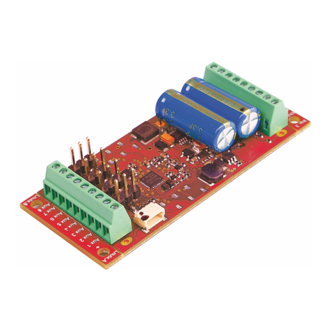
PIKO PluX16 User manual

Factory Default Settings
The factory settings are address 03, 28 speed steps, and the decoder automatically recognizes DCC- and
Motorola**-formats. In addition the decoder can be operated with a DC throttle.
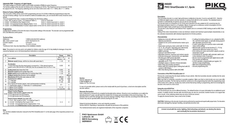
Technical Data
Decoder type: Multiprotocoll decoder 76150
Address range: 1-9999 (extended DCC address)
Max. motor current: 1,2 A
Ancillary outputs: 0,2 A each
Size: 22 x 15 x 3,8 mm
Hotline
In case of questions,we are ready to answer them for you!
Directly contact our technician: (49) 2045 858327
Mo - Fr except Wed 14:00-16:00hrs CET, Wed 16:00 - 18:00hrs CET
Warranty Statement
Every item is fully tested for functioning before shipment. If a defect occurs within two years after purchase,
the item will be repaired free of charge against presentation of purchase proof.
Please send it to Uhlenbrock Elektronik GmbH • Mercatorstr. 6 • 46244 Bottrop • Germany
Damages caused by overload or improper treatment are not covered by this warranty.
For EU only: Please note that decoders may only used in models carrying the EC conformance label.
Please note that decoders may only used in models carrying the EC conformance label.
All brand names mentioned are registered trademarks of the respective companies.
* Märklin is a trade mark of Gebr. Märklin & Cie. GmbH, Göppingen
** Motorola is a trade mark of Motorola Inc. Tempe-Phoenix (Arizona/USA)
PIKO Spielwaren GmbH, Lutherstr. 30, 96515 Sonneberg, GERMANY
Using the Page-Register to access CV addresses greater than 79
CV-addresses greater than 79 can only be accessed by the page-register. This is CV66.
If CV 66 has a value higher than 0, then the contents of CV 66 times 64 will be added to every address entered.
The entered value must lie in the range 1 to 64. After programming, reset the contents of CV66 to zero in order to
avoid unwanted offsets.
Example
Consider CV 82 to be programmed for a value of 15. First CV 66 must be set to a value of 1. Now CV 18 can be set
to a value of 15. The decoder will be programmed at CV82, as the offset held in CV 66 will be automatically added
to the CV address selected. If CV 82 is to be programmed with a value of 15, then CV 66 must rst be programmed
with a value of 1. Subsequently, CV 18 can be programmed with a value of 15. The decoder places the value 15 into
CV 82, which is derived from the multiplying the contents of the CV 66 (in the example 1) by 64 (thus 64) and then
adding the entered CV address (18).
Using the Offset-Register to set CV values greater than 79
CV-values greater than 79 can only programmed by employing the offset-register. This is CV 65. It holds a value offset
that will be multiplied by 4 and added to all CV values keyed in. After programming, reset the contents of CV65 to
zero in order to avoid unwanted offsets.
Example
Consider CV 49 to be programmed for a value of 157. First CV 65 must be set to a value of 25. Now CV 49 must
be set to value of 57. The decoder will hold 157 in CV49, because the offset of CV 65 will be multiplied by 4 (=100)
and added to 57.
Observe: When programming CV 65 and CV 66 the mutual contents are ignored.
Märklin Braking Section
The decoder reacts to a Märklin braking section (brakes with analogue current on the track), if CV29 Bit 2 and
CV49 Bit 7 are set to 1 (factory setting 1 and 0).
46121-90-7001 © PIKO 2014
#46121
Multiprotokoll decoder PluX16
Digital Operation on layouts using either DCC- or Motorola**-Format for locos with DC-Motors
Suited for locos with digital interface PluX16.
Properties
• Regulated Multi-protocol decoder for DCC, Motorola
• Suitable for DC and Bell armature motors up to 1 A
• Quiet motor running with 18.75 kHz control frequency
• 14, 27, 28, 31 and 128 speed steps depending on the data format
• Short (1-127) and long (128-9999) addresses
• NMRA compatible
• Minimum, maximum and middle speeds adjustable
• Main line programming (DCC)
• Shunting speed (half speed) switched with F3
• Acceleration/Deceleration switched with F4
• Direction dependent, dimmable lighting switched via F0
• 2 Special function outputs and light changing
• With SUSI interface for conneting sound modules or others for controlling of switchable special functions
(f1-f12) with the PluX interface
• Address identication for controlling the LISSY mini transmitter module via the SUSI interface with the PluX-interface
• Reacts to DCC brake signal (e.g. from Power 3) “Brake diode” or braking section in DC operation.
• All outputs have short circuit protection
• Conventional DC operation with automatic switching between DC and digital mode
• All CVs programmable by digital devices with DCC and Motorola formats
• Programmable via register, direct CV or page mode in DCC operation
• With output for the pick up switch 71750
• Updatable using Flash memory
Description
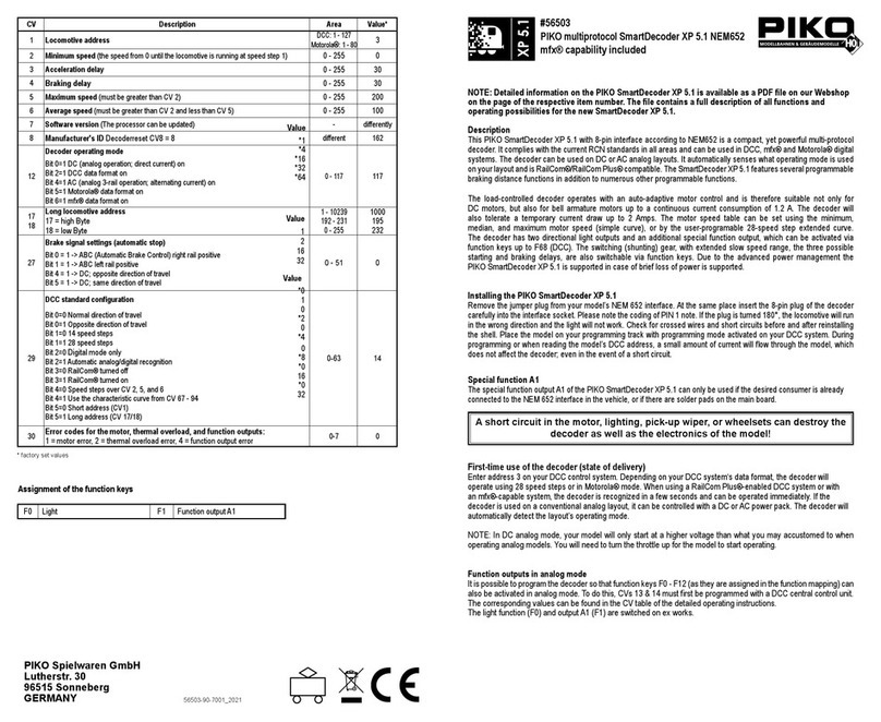
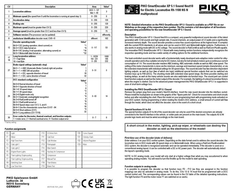
This Locomotive decoder is a small efcient multi-protocol decoder. It can be operated in DCC, and Motorola**
digital systems and also runs in DC analog mode. The operating mode will be detected automatically but can also
be locked manually. The decoder operates with a frequency of 18.75kHz and is therefore well suited for DC and
especially for Bell armature motors (e.g. Faulhaber, Maxon, Escap) up to a maximum power load of 1.2 A. Short
burst start up currents to 1.2 A are tolerated.
Motor characteristics can be controlled either by setting the minimum, maximum and middle speeds or via various
CVs for individual speed steps. Load regulation can be control via regulation parameters to a variety of individual
motors. The decoder provides two direction dependent lighting outputs and two special function outputsoperating
via function key f1 and f2.
All outputs are set at the 16 pole PluX interface at the intended contacts. Via f1 and f2 these both special function
outputs operate on the PluX interface at PIN 16 (f1) and PIN 18 (f2) .
Using f3 and f4 a shunting mode for slow speeds and Start/braking inertia can be activated. The decoder can be
programmed with the Intellibox, DCC and Märklin controllers. CVs can be programmed with all devices.

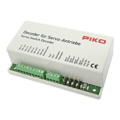
Fitting of the loco-decoder
Remove the shorting plug from the loco socket and insert the decoder plug into the loco socket.
Start-up
Check for proper wiring after installation using a wiring checker or an Ohmmeter. Make sure that the shell will not
touch the unit and that no wires can be “caught” (pulled, cut) when loco shell is placed back again on the loco frame
Digital and analog operation
Digital operation is possible for both DCC- and Motorola**-formats. Address 3 has to be set and it works with 28
speed steps. On conventional layouts the decoder can be run with DC or AC (Märklin*). All operating modes are
automatically recognized.
Connecting a sound module
A sound modul only can be connected, if the loco includes a SUSI interface socket or if you use the pickup switch
71 750 that is ted with a SUSI interface socket.
Insert the plug of the sound module into the SUSI interface socket.
Bit 1 in CV 49 must be programmed to value 1 and Bit 2 to value 0 (factory settings), so that the decoder transmits
the address identication for controlling the sound modul via the SUSI interface.
Note: Now it is not possible to connect the LISSY Mini-Transmitter 68 400 on the SUSI interface.
Connecting the LISSY mini transmitter module 68 400
Insert the LISSY mini transmitter plug into the SUSI interface socket. Then program Bit 1 in CV 49 to the value
0 and Bit 2 to the value 1, so that the decoder transmits the address identication for controlling the LISSY mini
transmitter module via the SUSI interface.
Note: Now it is not possible to connect a sound module on the SUSI interface.
Assignment of the 16-pole PluX interface
Pin PluX16 interface
3 SUSI - puls circuit
4 SUSI - data circuit
5 Decoder ground (behind rectier)
6 20 V (behind rectier)
7 Front light
8 Motor output 1
9 20 V (behind rectier)
10 Motor output 2
Pin PluX16 interface
11 n.n. = coding
12 2-rail: rail right / 3-rail: slider
13 Back light
14 2-rail: rail left / 3-rail: rails
15 Pickup switch output 1
16 Special function 1
17 Pickup switch output 2
18 Special function 2
Programming
The base of all possible settings are the CVs as dened in the DCC standard. The decoder can be programmed by
Intellibox, DCC central-units, or Motorola** central-units.
Programming by PIKO Digi-Power-Box and Intellibox
Regardless of the format which is to be used later, we recommend that you use the programming menu for DCC
decoders to program the decoder.
The PIKO Digi-Power-Box provides a convenient input menu to help you to program DCC decoders. Long addreses
do not have to be calculated laboriously, they can be input directly. The PIKO Digi-Power-Box / Inetllibox automatically
calculates the values for CV17 and CV18. Also the Bit5 of CV29 set to 1, so the decoder can use the long address.
For the precise procedure please read the the PIKO Digi-Power-Box / Intellibox manual.
Special case: loco addresses 80 to 255 in Motorola data format with the Intellibox
The Intellibox supports an address range up to 255 in the Motorola data format. The addresses 1 to 80 can also be
programmed with DCC programming without any problems. If however loco addresses above 80 are to be used,
the loco address must always be programmed as described in the chapter “Programming with a Märklin control
center”. After programming in this way the CV1 contains the value 0 and the decoder uses the Motorola address
above 80.
Programming by DCC Central Unit
Employ the programming menue of your unit to program the CVs in the mode it species. It is also possible to program
on the main. Use the exact procedure as specied in the operating manual.
Programming of extended addresses without menue
Should your central unit not support extended address programming, you have to calculate the values of CV17 and
18 yourself. Here is an example of how to calculate these values for address 2000.
• Divide the address by 256 (2000:256 = 7 remainder 208).
• Add 192 to the quotient (7).
• Insert the result (199) in CV 17.
• Insert the remainder (208) in CV 18.
• Important: Bit 5 of CV29 must be set to 1 in order to
activate extended address operation.
Calculating the conguration variables’ values
CVs 29 and 49 are used to congure your decoder. The value
is the sum of the desired functionalities per CV-table.
Example
Normal direction Value = 0
28 speed steps Value = 2
autom. analog-/digital recognition Value = 4
Speed table by CV2, 5, 6 Value = 0
Short address Value = 0
The sum is 6.
This value is the factory setting of CV29.
Programming by a Märklin* Central Unit
A Märklin* central unit can only program, but not read, any CV.
1. Switch off and back on.
2. Select decoder’s address and press F0 to have the headlights come on.
3. Set speed to zero. Switch the driving direction 5-8 times, untill the lights are blinking.
4. Key in the CV number like a loco address.
5. Again, shortly move control knob to reversing position. The loco lights will quickly ash four times.
6. Key in the CV value like a loco address.
7. Again, shortly move control knob to reversing position. Loco lights will slowly ash four times.
Repeat steps 4 - 7 for any other CV you want to program.
Finish the programming procedure by switching the central unit to „STOP“ or key in address „80“ and shortly move
control knob to reversing position.
Because a Märklin* central unit accepts only inputs between „01“ and „80”, a value of zero must be keyed in as „80”
Function CV29
Normal travel direction Reverse
travel direction
14/27 speed steps
28/128 speed steps
Only digital operation
Auto digital/analog switching
Speed steps in CV2, CV5 and CV6
Characteristics read from CV67-94
Short address (CV1, Register 1)
Long address (CV17 and CV18)
Wert
0
1
0
2
0
4
0
16
0
32
Bit
0
1
2
4
5
This manual suits for next models
1
Other PIKO Media Converter manuals

PIKO
PIKO 56424 User manual

PIKO
PIKO 35013 Quick guide

PIKO
PIKO SmartDecoder XP 5.1 Sound Next18 User manual

PIKO
PIKO 55274 User manual

PIKO
PIKO SmartDecoder XP 5.1 Sound User manual

PIKO
PIKO 46400 User manual

PIKO
PIKO SmartDecoder XP 5.1 User manual

PIKO
PIKO SmartDecoder 4.1 G User manual

PIKO
PIKO 56500 User manual
Popular Media Converter manuals by other brands

Extron electronics
Extron electronics HAI 100 4K user guide

Planet Networking & Communication
Planet Networking & Communication FT-902 Quick installation guide

Emotiva
Emotiva BIG EGO+ Getting started

Tributaries
Tributaries HDMI HC100 Operation manual

Lika
Lika CB59 quick start guide

Stagetec
Stagetec NEXUS compact TrueMatch quick guide