#56424 PIKO SmartDecoder 4.1 Sound PluX22
for diesel locomotives BR 364 / V60 H0
Multiprotocol
Description
The innovative PIKO Sound PluX22 SmartDecoder 4.1 is a compact, high-performance, multi-protocol next-generation sound decoder using 12-bit sound with a high sampling rate, 2.5-watt
power output, and a signicantly increased memory capacity. The decoder eliminates motor “hum” typical of older decoders, ensuring outstanding prototypical sound on multiple levels.
It can be used on DCC, Selectrix, and Motorola digital systems as well as in analog mode with DC or AC power. The decoder is RailCom® and RailCom Plus® compatable. The PIKO
SmartDecoder 4.1 automatically recognizes the layout’s operating mode (DCC or analog) and has multiple settings for a wide range of additional functions, including programming braking
distances.
The load-regulated sound decoder operates on a motor frequency of 18.75 kHz and is therefore suitable for DC and bell-shaped armature motors (ie. Faulhaber, Maxon, Escap) that
draw a 1.2A continuous current. Temporarily higher currents up to 2 A. are easily tolerated. The decoder masters both ABC braking and ABC slow speed mode. The motor speed curve is
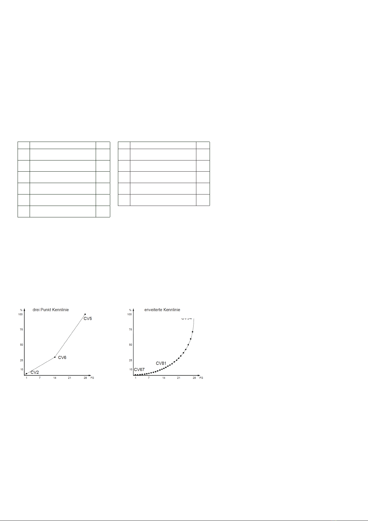
calibrated to minimum, average, and maximum speed (simple speed curve) or via an extended speed curve with individual settings for 28 speed steps. The decoder has two directional
lighting outputs as well as seven additional special function outputs. Extended-range slow-speed switching (shunting), acceleration settings, braking delays, and numerous sound functions
are activated via function keys.
Decoder properties
• Suitable for DC and bell-shaped armature motors rated up to 1.2A
• Ultra-quiet motor operation via 18.75 kHz operating frequency
• 14, 27, 28, and 128 speed steps, depending on the data format
• Supports short (1-127) and long (128-9999) addressing
• NMRA compliant
• RailCom® and RailCom Plus
• mfx®-capable (AC version)
• Adjustable minimum, average, and maximum speeds
• Adjustable extended-range speed curve
• Switching (shunting) mode gear
• 3 adjustable startup and braking delays, each activated via F0 - F28
• Dimmable, directional lighting outputs
• 7 adjustable special function outputs, dimmable and directional-dependent
• Adjustable light and function outputs for analog operation
• Adjustable secondary dimming functions for lighting outputs, activated via A1 to A7
• ESimple function mapping; F0 - F12 for lighting, A1 to A7 for acceleration, braking, and
switching (shunting) modes
• Extended function mapping on F0 - F44 for activating or switching multiple
linked outputs
• Passenger car lighting can be switched off
• Adjustable ash function with variable on/off timing
• Adjustable 2-phase blinking function
• Load-dependent smoke generator control
• Firebox lighting effect with adjustable parameters for brightness and icker rhythm
• Switching (shunting) mode coupling and switching (shunting) tango
• Adjustable on/off option for hiding light and function outputs
• Fade in/out lighting effect: lamps reach their maximum brightness over an adjustable
length of time
• Fluorescent lighting effect with switch-on ickering effect and adjustable ash time and
number
• 8 PWM banks each with 64 modulation entries used, for example, for American lighting
effects
• Automatic braking via DCC brake signals, braking with DC analog or ABC braking blocks
• ABC restricted speed movements via LENZ BM2 block stopping module
• 2 adjustable braking distances in centimeters that are activated via ABC, DC, or DCC
braking signals, as well as via speed step 0 using an adjustable speed step threshold
• 2 motor control modes for precise motor control with numerous parameter settings
• Motorola-compliant operation with 3 addresses for functions F1 - F12 when used with a
Motorola-based DCC system
• All outputs are protected against short circuits
• Error memory for motor and function outputs, as well as automatic overheating shutdown
• Conventional DC and AC analog operation that automatically switches to the respective
operating mode
• All CVs must be programmed with a Motorola-based DCC digital device
• Programmable in DCC via register mode, direct CV programming, or page mode
programming
• Programming On the Main (DCC))
• Decoder programming lock
Sound functions
• All sounds in 12-bit resolution
• 8-channel sound system
• 128 MB of sound memory for up to 495 seconds of digitized prototype sound
• 22.05 kHz sampling rate
• Powerful digital power amplier with 2.5 watt output
• User activated and deactivated sound sequences when engine sound is switched on and
off
• Up to 31individual sounds, switchable via 28 function keys
• Load-dependent sound variation (acceleration, upgrade, downgrade, braking, idling, etc.)
• Adjustable volumes for overall sound and for individual sounds
• Doppler effect sound (i.e. entering tunnel, grade crossings) Random sounds such as coal
shoveling or engine fans
• Automatic brake squeal
• Adjustable speed thresholds for switching (shunting) sound
• Sound projects easily programmed via PIKO SmartProgrammer/Tester
• And much more..
Installing the PIKO SmartDecoder 4.1 Sound
Remove the jumper plug from the PluX22 interface of your model. Replace it with the Sound decoder, carefully inserting it into the interface socket. Note the missing PIN 11. Install the 4 - 16
Ohm speaker as shown in the „Spare parts list“ diagram. Make sure that no bare wires or wire tips are touching each other, and that there are no short circuits, even after replacing the model
shell. The model should then be placed on a dedicated programming track, with programming mode activated on your DCC system. During programming or reading the model’s DCC address,
a small amount of current will ow through the decoder that does not damage it, nor is it an indication of a short circuit.
Auxiliary functions A1 to A7
The Sound decoder’s auxiliary function outputs A1 to A7 can only be used if they are connected to auxiliary functions, and those functions are already connected to the PluX 22 interface in the
model, or if solder pads are available on the main circuit board.
SUSI interface
The SUSI interface of this sound decoder is connected to the PluX22 interface. If the main circuit board of the model is equipped with a SUSI interface, another PIKO sound module with
SUSI can be connected to it. The specic CVs that should be programmed for their respective applications can be found in the CV table.
ATTENTION: Soldering on the decoder itself should only be done by experienced modelers using the appropriate equipment. Decoders damaged by improper handling will not be covered
by the warranty.
First-time use of the decoder (state of delivery)
Enter address 3 on your DCC control unit. Depending on the data format used, the sound decoder will operate in DCC mode with 28 speed steps or in Motorola mode. When using a RailCom
Plus®-capable DCC system (eg PIKO SmartControl), the decoder is automatically recognized within seconds and can be operated immediately. If the decoder is used on an analog layout,
it can be controlled with a traditional DC or AC throttle. The layout’s operating mode is detected automatically by the decoder.
Analog DC/AC operation
This sound decoder is suitable for analog DC or analog AC operation, which is detected automatically. Please note that trouble-free operation using PWM (Pulse Width Modulation)-equipped
throttles cannot be guaranteed due to the large number of differing systems available on the market.
A short circuit in the motor, lighting, gearing, or wheelsets will destroy the decoder
and possibly all the electronics of the model!