Digital Programming
The PIKO Switch Decoder for Servo Machines can be setup in Motorola or DCC-system via solenoid controlling menu or via DCC-CV-
programming.
In analogue programming mode not all setups can be changed.
Programming by Key and Solenoid Command
All settings for the stop positions and the servo machine turning speed are easily set by the digital center, or another
control device, with which one can control solenoids. The desired servos should be connected to the outputs that are to be programmed since
the servo decoder acknowledges the setting of the servo parameters, during programming, with a movement of the respective servo.
1. Activating Programming Mode
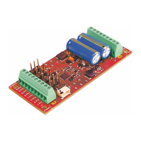
Press the programming button on the decoder and keep it pressed. The control LED shines.
2. Selecting Data Format
DCC format is selected if the LEDs are blinking at servo output 1 and 2.
Motorola format is selected if the LEDs are blinking at servo output 3 and 4.
First the LEDs 1&2 are blinking and after some seconds the LEDs 3&4 and so on.
The programming button has to be pressed, if the LEDs show the required data format.
Note: If the decoder no longer reacts to key inputs from the input device, the wrong data format was selected!
3. Choose servo machine output to program
Press the key repeatedly until the LED of the servo machine on the desired output is shining.
4. Setup the solenoid address for the selected servo machine output
On digital center or another control device which can switch solenoids, operate one of the two keys (red or green) for controlling this servo
later. The servo decoder conrms the command with a short shivering of the servo on this output.
5. Selecting solenoid keys for [+] and [-]
In order to be able to set up stops and the speed of the servo during programming, two keys must be specied which will be used as [+] and [-]
key. From the digital center, or another control device which can switch solenoids, press the key which is to be used as [+] key. The solenoid
address of this key must not be the same as the previously selected solenoid address. The servo decoder conrms the command with a short
shivering of the servo on this output. In the same way, the key which is to be the [-] key is determined.
Note: After programming, this allocation is deleted so that these keys can be used on the layout as normal.
6. Setting the stop positions of the Servo machines
Using the address setup in step 4, the servo can now be moved to stop position “red” with the red solenoid key. With the help of the [+] and [-]
keys, specied in step 5, the stop position of the Servos is adjusted accordingly. For this the [+] or [-] key is repeatedly pressed until the desired
position is reached. With the green solenoid move the servo to the stop position "green" as described above.
When desired positions are xed, the servo must be switched to the "red" and "green" stop positions 3 times (thus red-green-red-green-red-
green) without changing the setting, in order to go to the next programming step (keys in accordance with step 4).
7. Setting the speed of the Servo machine
The servo machine now repeatedly moves back and forth with the set speed between the two stop positions. The speed of the movement can
be increased or decreased with the [+]and [-] keys, specied in step 5.
8. Terminate Programming
When the desired speed is adjusted, one of the two keys which change the servo position is operated, (keys in accordance with step 4).
Programming for this servo output is complete and the servo decoder is ready for the programming of the next output. The selected settings
are permanently stored.
Note: If the programming is terminated prematurely, as if the track power is switched off, then the selected settings are stored.
CV Programming with DCC Devices
The decoder can be programmed with the PIKO Smart Control and any DCC center that permits 3 digit numerical values. Use the
programming menu of your DCC center to select and program the decoder CVs. The exact process will be outlined in the center’s manual.
Connection of the servo decoder for programming
For programming the PIKO Switch Decoder for Servo Machines it must be individually connected to a programming
track. The desired servo machines are connected to outputs which are to be programmed.
Conguration of the PIKO Switch Decoder for Servo Machines
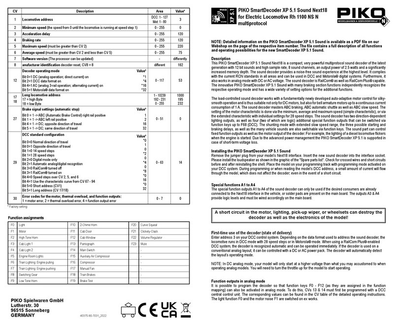
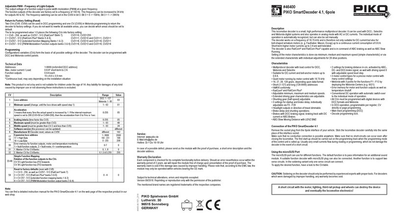
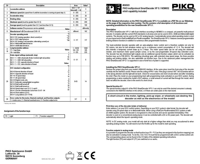
CV 119 is used to specify different decoder settings. If the power on the different servo outputs is always switched on or only during servo
operation and if the operating mode is Motorola or DCC: The entered value
is calculated from the CV table in which the values of the desired
functions are added.
Example
Output 1 power always on value = 1
Output 2 power always on value = 2
Output 3 power always on value = 4
Output 4 power always on value = 8
Operating mode DCC value = 0
Sum of all values is always 15. This value is preset in CV 119 by the factory.
Setting time / turning speed (CV 124)
Time constant by which servo position is incremented or decremented in 1 ms steps.
Process time = (difference between "red" and "green" values) *setting time *1 ms
Setting time = ___desired turning time in seconds * 1000 ___
difference of the stop positions red and green
Programming with PIKO SmartControl
Before programming you need to setup a new Switch Panel in the PIKO SmartControl App. This Switch Panel must include the addresses for
the servo machines to be programmed and additional two more items, with two additional, different addresses. These two additional addresses
will act as [+] and [-] during the programming.
Example: You want to connect two servo machines on contacts "servo 1" and "servo 2" and give those servos the new addresses 21 and 22.
As [+] and [-] buttons we will use digital addresses "23" and "24" in this example.
1. Create four new accessory items that are saved with the addresses mentioned above.
2. Put those four items into a new Switch Panel and safe it.
3. Press the programming button and keep pressed. The control LED will start to shine and you can choose the data format for programming
4. Choose Data Format
DCC format is selected if the LEDs are blinking at servo output 1 and 2.
Motorola format is selected if the LEDs are blinking at servo output 3 and 4.
First the LEDs 1&2 are blinking and after some seconds the LEDs 3&4 and so on.
The programming button has to be pressed, if the LEDs show the required data format.
Note: If the decoder no longer reacts to key inputs from the input device, the wrong data format was selected!.
5. Choose servo output for programming
Press the key repeatedly until the LED of the servo machine on the desired output is shining.
6. Now touch the accessory item in PIKO SmartControl Switch Panel that is stored with address "21". The decoder will conrm the new
address with a short shivering of the servo 1.
7. As next, touch the accessory stored with address "23" to setup the [+] button. The decoder will conrm this address with a short shivering
of servo 1.
8. Then, touch accessory stored with address "24" to setup the [-] button. Decoder will conrm with short shivering.
9. Now the stopping positions right and left will be setup:
Setup of the rst position:
The programming will start "from the center position" of the servo machine (center between maximum positions). Depending on the
assigned symbol (f.e. "switch right") please take care for the correctness of the symbol. Depending if the switch is "open" or "closed" the
programming should start to left or right ( [+] or [-] direction).
Setup of second stop position:
Touch the symbol with address "21" (servo 1) to move it into it's other position (in this case: back to center after rst position is setup). Now
repeat step 9 again to nd the second stop position.
10. Setup of setting time / turning speed:
Touch the symbol with address 21 (servo1) 6 times now, so that the servo will move 3 cycles. The decoder will conrm the position and
start to move the servo machine repeatedly between those positions to setup the speed. With the buttons for [+] and [-] ("23 and 24") you
can setup the speed then.
11. For nishing the programming, touch Servo 1 / Address 21 six times again (3 cycles). The decoder will stop to move the servo and the
programming LED will stop to shine. Programming is nished and the values are stored permanently.
Note: If a power-off appears during the programming the values will not be stored. Programming must be repeated then.
12. Programming of servo machine 2 to new address 22: Repeat the points 5 to 11 with the new address "22" in the PIKO SmartControl Switch
Panel.
On our FAQ-pages under www.piko-shop.de you can nd a tutorial video of the programming procedure, too.
Bit Function CV 119 Value
0
Power Output 1
only on during servo movement immer
always
0
1*
1
Power Output 2
only on during servo movement immer
always
0
2*
2
Power Output 3
only on during servo movement immer
always
0
4*
3
Power Output 4
only on during servo movement immer
always
0
8*


