Pilot Communications EV Lite User manual

Pilot EV Lite
Quick Installation
Guide

17/01/2020 / DC1 / Version2
Tools required
# Name Remark
1Philips screwdriver Electric with bit preferred
2Hex (M4) screwdriver Electric with bit preferred
3Level –
4Stainless steel anchors Size M10
5Stainless steel bolts M10 to t the anchors
6Drill –
732A Type C Circuit Breaker –
85 core 6mm2 cable Length as required
9Pencil –
2 +44 (0) 1606 59 66 22

17/01/2020 / DC1 / Version2
3
Prerequisites
• This type of installation requires an electrical background.
• When unpacking the contents of the kit, it is crucial to perform a
visual check to confirm that none of the parts are damaged or
broken.
• Prior to installation, make sure to disconnect the main circuit
breaker (CB).
• Locate the serial number (S/N) on the attached test report and
confirm that the same serial number is configured in the
Chargepoint management system with the Certified Pilot EV
team.
Figure 1 S/N Sticker sample
This type of installation requires an electrical background.
When unpacking the contents of the kit, it is crucial to perform a visual check to
conrm that none of the parts are damaged or broken.
Prior to installation, make sure to disconnect the main circuit breaker (CB).
Locate the serial number (S/N) on the attached test report and conrm that the same
serial number is congured in the Chargepoint management system with the
Certied Pilot EV team.
Prerequisites
www.thepilotgroup.co.uk

17/01/2020 / DC1 / Version2
Make sure to always follow your local electrical regulations.
The Pilot EV Lite installation should only be carried out by a certied installer.
The below instructions are a guideline and provided for reference only. You are solely
responsible for following all applicable electrical safety procedures, codes, methods,
and materials provided as per the instructions below.
Prior to installation, make sure to disconnect the main circuit breaker (CB).
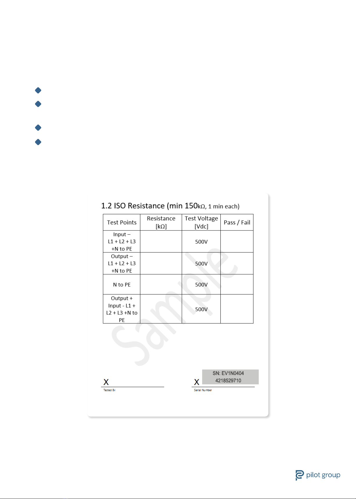
Carry out a visual inspection to verify that none of the parts are damaged.
Prerequisites
There is risk of re or electric shock. Do not alter, relocate, drill or remove any
component without consulting with the Pilot EV certied team.
Pilot EV is and will not be liable for any modications or results of such modications
done to the product during or after installation.
Installation must be carried out in dry conditions only.
Ensure that all power is turned o using a voltmeter or an equivalent device before
performing any installation.
ATTENTION
!!
WARNING
!!
CAUTION
!!
4 +44 (0) 1606 59 66 22

17/01/2020 / DC1 / Version2
Place the wall mount on the
designated wall.
It is recommended to use a level
to ensure that the template is
aligned straight.
Mark the holes with pencil.
Mark the mount location1
5
1Mark the mount location
2DDrill holes
Place the wall mount on the
designated wall.
It is recommended to use a
level to ensure that the
template is aligned straight.
Mark the holes with pencil.
Using a drill make the holes
prior to installation.
Confirm that the hole
and anchor size are identical.
Using a drill make the holes prior
to installation.
Conrm that the hole
and anchor size are identical.
Drill holes
5
1Mark the mount location
2DDrill holes
Place the wall mount on the
designated wall.
It is recommended to use a
level to ensure that the
template is aligned straight.
Mark the holes with pencil.
Using a drill make the holes
prior to installation.
Confirm that the hole
and anchor size are identical.
2
www.thepilotgroup.co.uk

17/01/2020 / DC1 / Version2
Insert appropriate screw anchors
into the hole, ensuring that they t
the bolt size and wall type.
Install screw anchors3
Attach the bracket by application
of bolts.
Install the bracket4
6 +44 (0) 1606 59 66 22

17/01/2020 / DC1 / Version2
Using the Hex screwdriver, unfasten six screws (three from each side)
to dismantle the front panel.
Dismantle the front panel5
www.thepilotgroup.co.uk

17/01/2020 / DC1 / Version2
Dismantle the cable cover
Insert the cable
6
7
Using the Philips screwdriver,
unfasten the two screws to
dismantle the cable cover.
Insert the cable through the left
hole and use the keystone cable
clamp to secure it.
8 +44 (0) 1606 59 66 22

17/01/2020 / DC1 / Version2
Connect the cables according to the diagram:
L = Brown
N = Blue
PE Earth \ PE \ Ground = Yellow Green
Make sure to perform the appropriate PE connection test based on
the current edition of the IET Wiring regulations.
Connect the cable8
!!
www.thepilotgroup.co.uk

17/01/2020 / DC1 / Version2
Using the Hex screwdriver, fasten the six screws (three from each side)
to assemble the front panel.
Assemble the front panel9
10 +44 (0) 1606 59 66 22

17/01/2020 / DC1 / Version2
Hang the device on the bracket and make sure it ts securely.
Hang the device10
www.thepilotgroup.co.uk

17/01/2020 / DC1 / Version2
Using the M4 screw and nut (included) securely x the device to
its location.
Secure the device11
12 +44 (0) 1606 59 66 22

17/01/2020 / DC1 / Version2
Switch on the main CB - Circuit Breaker (Switch I).
Power up the device12
www.thepilotgroup.co.uk

17/01/2020 / DC1 / Version2
Getting Started
Step 1. Connect Nozzle
Inspect the charger for any visible damage. Do not use the charger if damaged.
Connect nozzle end to the car. Charging starts automatically.
For the Pilot EV Lite Socket model, make sure that the other end of the cable is
connected to the charger.
Step 2. Remove Charger
Do not unplug the charger while charging.
Stop the charging process in the car. Release the latch on car’s charge port
(if applicable).
Unplug the charger from the car.
Close the car’s charging port cover.
Step 3. Charging Status Screen 11 Power up the device
The charging status is indicated by the dierent logo led lights
and via the LCD screen (depending on the model).
No Light – Charger is not receiving any power (power-loss)
Flashing Blue Light – Charger initialization process.
Constant Blue Light – Charger is ready for use.
Flashing Green Light – Charging in progress.
Constant Green light - Charging is complete.
Flashing Red light – An error detected. Charging immediately stops.
Connect Nozzle13
14 +44 (0) 1606 59 66 22

17/01/2020 / DC1 / Version2
Troubleshooting
If charging slows down or stops unexpectedly, check the car’s infotainment for
error messages.
Unplug the charger from the car - Make sure the cable and nozzle are not
damaged.
Check the signaling light on the charger. The number of red ashing light may
indicate the following issues:
Single fast ashing – Problem with switching elements
Two ashing lights – Problem with the residual current device
Three ashing lights – Problem with the PE or neutral wire
Four ashing lights – Overvoltage
Five ashing lights – High temperature
Six ashing lights – Unsupported charging mode
For further assistance, contact evsupport@thepilotgroup.co.uk
Troubleshooting14
www.thepilotgroup.co.uk

www.thepilotgroup.co.uk +44 (0) 1606 59 66 22 Pilot Group Limited, 15 Carnarvon Street
Manchester M3 1HJ
As a privately-owned business that has traded internationally since 1992 from our base in Manchester, we believe in working
closely with our customers to form long lasting and mutually benecial partnerships.
At Pilot Group we believe in using technology to make the places we live and work SMART, SAFE and SUSTAINABLE.
At Pilot Group we supply Energy Management Systems, LED Lighting,
Trac Controls, Technology, and Electric Vehicle Charging solutions.
Table of contents
Other Pilot Communications Automobile Accessories manuals
Popular Automobile Accessories manuals by other brands

NINGBO LONGMA VEHICLE INDUSTRY
NINGBO LONGMA VEHICLE INDUSTRY LM406 Instructions for use

Blueant
Blueant Supertooth Light Specifications

Cequent
Cequent Rola 59504 manual

ARB
ARB Airlocker RD143 installation guide

RTR
RTR 1992-7001-01 installation instructions

Whelen Engineering Company
Whelen Engineering Company M4 Series installation guide