PROCESSING START TANGENT ARC CALCULATION FOR INTERNAL
Before starting processing, always consider the tangent arc distance to avoid chipping or breaking the insert (figure 6).
FIGURE 6
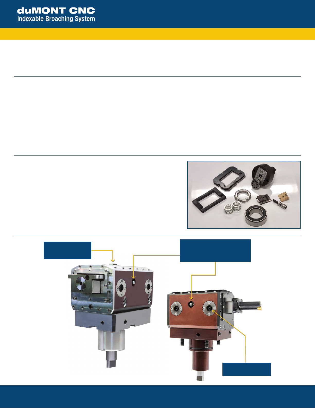
Motorized Slotter
15 Merrigan Way |South Deerfield, MA 01373 | 413-350-5200 |PilotPrecision.com | ISO 9001 : 2015
CUTTING PARAMETERS
For each material, based on our experience, the recommended parameters are:
35 mm Ram Stroke 50 mm Ram Stroke 65 mm Ram Stroke RPM = cut speed ÷ (ram stroke x 2)
Insert Width Insert Width Insert Width Cutting speed Cut per Stroke Min / Max
Aluminum
5/8 in. 5/8 in. 5/8 in. 1496 in./min. .0023/.0059 in.
Soft steel
9/16 in. 9/16 in. 9/16 in. 1299 in./min. .0015/.0027 in.
Cast iron
9/16 in 9/16 in. 1/2 in. 1102 in./min. .0015/.0027 in.
Common steel
9/16 in 9/16 in. 1/2 in 1181 in./min. .0011/.0019 in.
Hardened steel
1/2 in. 1/2 in. 3/8 in. 984 in./min. .0007/.0015 in.
Stainless steel
1/2 in 1/2 in. 3/8 in. 984 in./min. .0007/0015 in.
Plastic
3/4 in. 3/4 in. 3/4 in. 1574 in./min. .0027/0059 in.
Bronze-Brass
9/16 in. 1/2 in. 1/2 in. 1181 in./min. .0011/.0023 in.
PROGRAMMING BEST PRACTICES
CAUTION: Consider tangent arc at the start of processing, under the lathing diameter (figure 6).
• Set feed to units per revolution.
• Set speed to revolutions per minute.
• For internal features, use clockwise live spindle direction; for external features use counterclockwise live spindle direction.
• Spindle RPM = SurfaceSpeed / (StrokeLength x 2)*
*Be sure to convert units to match if necessary
RETRACT DURING THE RETURN STROKE
During the return phase, the tool detaches from the processed surface by 0.25 mm. This movement is essential to preserve the integrity of
the insert. This is automatic and a function of the elliptical path referenced on page 1.