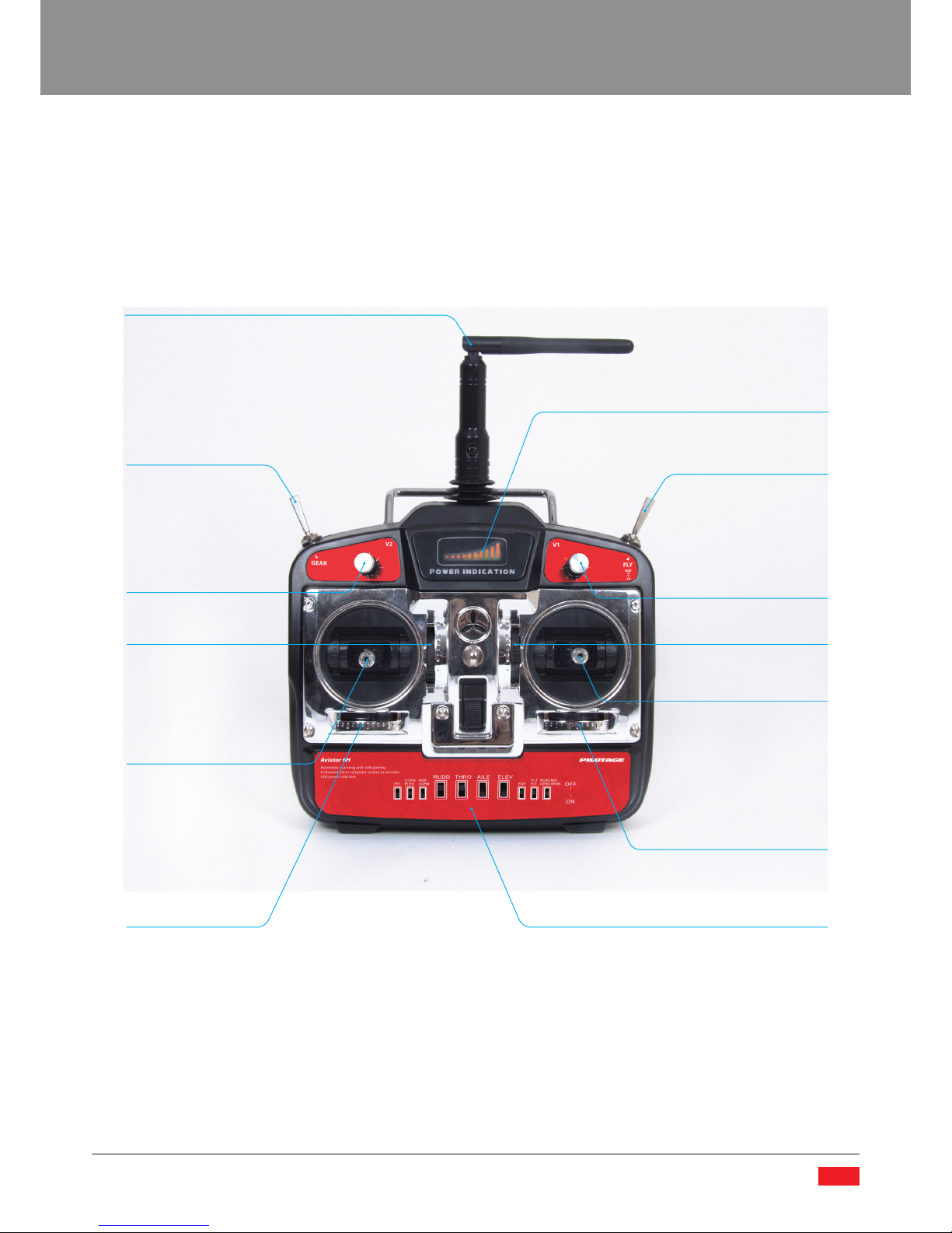
PILOTAGE Stinger 3D 250 User manual

www.pilotage-rc.com
Мир радиоуправляемых моделей
PILOTAGE STINGER
HELICOPTER
User's Manual
Инструкция по сборке
и эксплуатации

Contents
Introduction ....................................................................................................................................................................................................... 2
Warranty .............................................................................................................................................................................................................. 2
Precautions ......................................................................................................................................................................................................... 2
Radio Information ............................................................................................................................................................................................4
Package Contents ............................................................................................................................................................................................. 4
Technical Specifications ................................................................................................................................................................................. 4
Transmitter (Tx) Overview ............................................................................................................................................................................. 5
Gryo Overview .................................................................................................................................................................................................13
Electronic Speed Controller (ESC) Overview ........................................................................................................................................14
Charging the Li-Pol Battery .........................................................................................................................................................................14
Helicopter Overview .....................................................................................................................................................................................19
Preparing the Model for Flight ..................................................................................................................................................................20
Flying the Model Helicopter .......................................................................................................................................................................23
Exploded View and Spare Parts Listing ..................................................................................................................................................28
Contact ...............................................................................................................................................................................................................55
Notes ...................................................................................................................................................................................................................56
Введение ..........................................................................................................................................................................................................30
Меры предосторожности .........................................................................................................................................................................30
Информация об используемой аппаратуре ....................................................................................................................................31
Комплектация ................................................................................................................................................................................................31
Технические характеристики ..................................................................................................................................................................31
Передатчик (Tx) .............................................................................................................................................................................................32
Гироскоп ...........................................................................................................................................................................................................40
Регулятор .........................................................................................................................................................................................................41
Зарядка Li-Pol аккумулятора ...................................................................................................................................................................41
Вертолет ...........................................................................................................................................................................................................45
Подготовка модели к полету ...................................................................................................................................................................45
Управление моделью вертолета ...........................................................................................................................................................49
Схема сборки модели и список деталей ............................................................................................................................................53
Контактная информация ...........................................................................................................................................................................55
Для заметок .....................................................................................................................................................................................................56
ENG
RUS
www.pilotage-rc.com
PILOTAGE STINGER 3D HELICOPTER

INTRODUCTION
Thank you for your purchase of Pilotage’s Stinger 3D 250 Model Helicopter. We hope that this model will provide you with hours
of enjoyment and entertainment. This model has been designed to suit a wide array of helicopter modelers with various levels
of experience. This model is not recommended as a first model helicopter, but is suited to those who have mastered the basics
of helicopter piloting. We likewise recommend that you practice extensively on a modeling simulator to keep your skills finely
honed.
Please keep in mind that this product is not a toy, it is a sophisticated, functional, flying model. It is important that you review all
the below warnings, precautions and warranty terms. Please retain these instructions and the box for further reference.
Due to the fact that Pilotage Marketing LLP is constantly improving the quality and functional characteristics of its products,
some details, colors, and functions may differ slightly from the images presented on the box and in the instructions.
WARRANTY
Pilotage Marketing LLP guarantees that this model is free from defects both in material and craftsmanship on the date of
purchase. This guarantee does not cover any component parts damaged by use or modification. Pilotage Marketing LLP’s liability
will under no circumstances exceed the original cost of the purchased model. Moreover, Pilotage Marketing LLP reserves the
right to change or modify this warranty without notice.
If upon purchasing this product the buyer finds defects to the product as a result of the manufacturing process, he/she is
recommended to return this product to any Pilotage store located in the country of purchase to exchange or refund the product.
Given that Pilotage Marketing LLP has no control over the final assembly or use of this product, Pilotage Marketing LLP shall
assume no liability for damage caused resulting from the use by the user of the final user-assembled product.
By using this product the user accepts all resulting liability. If the purchaser of this product is not prepared to accept the liability
associated with the use of this product, they are advised to return this model within 14 days of the initial purchase to any
Pilotage store in the country of purchase. The product must be in complete and unused condition along with receipt of purchase
at the moment of return.
The terms of the above warranty are not applicable on the territory of the Russian Federation.
PRECAUTIONS
1. Be sure that limbs, hair and loose clothing are clear of the rotor blades at all times.
2. Be sure that all spectators are behind you and the model at all times when flying.
3. Prior to takeoff, inspect the model for any damage that may have resulted from the previous flights.
4. Only use the blades that are supplied with the model, or spare blades explicitly designed for this model.
5. Discard any broken, cracked, or nicked blades. Never attempt to fly this model with blades that are in disrepair.
6. Assemble the model according to these instructions. Do not alter or modify the construction of this model; if you do so the
warranty for this product will be void.
7. Test the range and operational integrity of this model prior to each flight to insure that all components are in good repair
and that the model remains structurally sound.
8. Fly only on calm days when wind is still, or indoors in a sufficiently large space to safely maneuver your model. Please note
that even a light wind can disrupt the flight performance of your model.
9. Never leave the model in direct sunlight for prolonged periods of time. Never use this model when the ambient temperature
is above 104°F/40°C or below 41°F/5°C.
10. Never use this model near power lines, radio towers, or other locations where there is known high radio wave or
electromagnetic activity.
11. Do not allow water or liquid to touch the model or any of the components.
12. Store the model in a cool dry location as high humidity can damage the model and its components.
13. Protect the model from bumps, jolts, and concussions from other hard objects as this could damage the model.
14. Keep the model clean of dust, mud and dirt.
15. Never place foreign objects on top of the model.
16. Use the model ONLY in wide open spaces that are free of people, or at your local RC flight club. Indoor spaces should not
be less than 82’x50’x23’/25x15x7m. When flying the model outdoors we recommend flying above a soft surface such as a
grassy field.
17. NEVER use the model near populated pedestrian areas. This could lead to damage of property or injury to bystanders.
18. Prior to takeoff, always check that transmitter and receiver batteries are fully charged and are fresh. As battery power
2

decreases the quality of the radio signal diminishes and control over the model could fail.
19. Please dispose of used batteries and electronic components in accordance with your municipal and federal regulations
relating to the disposal of electronic waste.
20. Ensure that the antennas on the Tx and Rx are fully extended and that the Tx antenna points upwards and not toward the
ground when holding it.
21. Keep in mind that those in your vicinity may also use radio control models. Please check prior to takeoff that you are using a
unique frequency to all those around you. Not doing so may cause you and others to lose control over your models.
22. If the model does not properly respond to signals, land immediately and do not attempt to use the model until the cause
has been determined and fixed.
23. After flying, switch off the power on the vehicle and the transmitter and remove the batteries from the Tx and model.
24. If the model becomes dirty, use a clean dry cloth to clean it. Never use solvents as they will damage the structural integrity
of the model’s plastic components.
25. Never attempt to catch the model with your hands while in flight. Any slight wind or motion of the controller’s fingers may
direct the model in your direction which could cause damage or severe injury.
26. Prior to launching your model, ensure that the gyro is level and securely fastened to the mounting platform. If it is not level
and well secured on the platform it will affect the flight performance of the model.
27. Never attempt to fly the model in weather conditions that reduce your line of sight such as light rain or fog.
28. The brushless motor may get very hot when the model is in use. In order to lengthen the service life of your motor we
recommend allowing the power system to cool for 10-15 minutes between flights.
29. Please keep in mind that you as the operator are solely responsible for the safe operation of the model. In order to ensure a
long safe product life adhere to all warnings and precautions as stated in this manual.
Attention
1. This product is not suitable for children under 14 years of age. Adult supervision of children under this age is highly
recommended.
2. This kit contains a number of small parts which are fragile and may act as choking hazards. Please store and assemble this
model well out of the reach of small children.
3. Only use batteries of the same or equivalent type.
4. The supply terminals are not to be short-circuited.
5. Do not use new and old batteries together. Do not mix different brands or kinds of batteries.
6. Make sure to insert batteries with correct (+) and (-) polarity.
7. Do not short-circuit this model, which is potentially dangerous.
8. If the model gets wet, dry it, and stop playing to avoid short-circuiting that may cause hazards.
9. Do not disassemble and resolder this model.
10. Never attempt to dispose of the model or the batteries in a fire, components are explosive and may release toxic gases.
Battery and Charging Safety:
This model is powered by a removable, 7.4V lithium-polymer (Li-Pol) battery. Damage to your Li-Pol battery can cause the cell to
catch fire or explode. Please carefully review and adhere to the following safety guidelines:
1. Only use chargers explicitly designed to charge Li-Pol batteries for the battery pack that comes with this model, such as the
charger included in this kit.
2. Never reverse the polarity while plugging in the charger connector.
3. Never leave your model unattended while charging.
4. Never leave or store your model with the charger connected to the battery pack.
5. Never leave or store your model with the battery connected to the model’s input lead.
6. Never use the model if the battery becomes hot, emits an odor or leaks a fluid.
7. If battery fluid touches your skin flush it well with water and then consult a medical professional.
8. Never attempt to burn or incinerate this model or the battery pack.
9. When disposing of this model tape the leads to prevent short circuiting, and take it to a recycling center that is qualified to
dispose of electronic waste and batteries.
10. Do not charge/discharge (use) or store this model at temperatures below freezing or above 113°F/45°C.
11. Charge the battery pack in a fire proof location, well away from potentially flammable items.
12. Never short-circuit the model.
www.pilotage-rc.com
3

RADIO INFORMATION
This radio system is in compliance with part 95 of the F.C.C Rules. Operation is subject to the following two conditions.
1. This device may not cause harmful interference.
2. This device must accept any interference received, including interference that may cause undesired operation.
Note: Unauthorized changes or modification to the transmitter and/or receiver may void the user’s authority to operate the
equipment. Refer to the label on the box, on the model, on the transmitter or in the instructions to determine this model’s
operational frequency. Never operate more than one model on any given frequency as operational interference may occur.
PACKAGE CONTENTS
4. AC mains adapter cord
5. Li-Pol Charger Simplex 3
6. Foam Blade Holder
7. Hex Wrench
17.3”/438mm
4.1”/105mm
6.3”/161mm
16.5”/420mm
Brushless Motor
10.6oz/300g
7.4V 800 mAh Li-Pol
Electronic Gyro w/ Heading Hold.
.24oz/7g 4pcs
Required for Operation:
8pcs AA batteries
1. Transmitter (Tx)
2. Pilotage Stinger 3D Model Helicopter
3. 7.4V Li-Pol Battery
Main Rotor Diameter
Tail Rotor Diameter
Height
Length
Main Motor
Flying Weight
Battery Type
Gyroscope
Servos
TECHNICAL SPECIFICATIONS
2
76543
1
4

Battery Power Indicator
Flight Mode Toggle
Pitch Trim Lever
Pitch/Roll Control Stick
Roll Trim Lever
(V1)Throttle Curve/
Pitch Regulator (PIT)/
Regulator Gyro
Sensitivity
Antenna
Gear Toggle Switch
(V2) Exponentials/
Pitch Limit (PIT)/
Directional Mixer
Throttle Trim Lever
Throttle/Yaw Control Stick
Yaw Trim Lever Dip Switches
TRANSMITTER TX OVERVIEW
Transmitter Front
This model is equipped with a six channel transmitter that is simple and intuitive to use. It features a battery power indicator,
it allows you to adjust the throttle curve, blade pitch, and the gyro sensitivity. This Tx also features a toggle that switches flight
mode from normal (NOR) to 3D.
www.pilotage-rc.com
5

Function Overview
1. Left Stick -Throttle/Yaw: This stick controls your model’s altitude and directional control. Press this stick up and the model
will ascend by increasing the power supplied to the motor and increasing the pitсh of the main rotor blade increasing lift
forces. Press the stick downward and the model will descend because power will be reduced to the motor and the pitch
of the main rotor blade will decrease reducing lift forces. When the stick is fully down and the Flight Mode Toggle is in the
NOR position the motor should be completely off and will not drive the main rotor. When in the normal (NOR) flight mode,
holding the stick close to the central position allows the model to hover in mid air. When the stick is pushed to the right, the
model will rotate in a clockwise direction, when the stick is pushed to the left the model will rotate in a counterclockwise
direction.
2. Right Stick - Pitch/Roll: This stick moves your model forward and backwards. It also moves the helicopter to the left and right
along the horizontal plane. Move the stick up and the helicopter will move forwards, move the stick back (towards you) and
the model will move backwards. If you move this stick to the right, then the helicopter will move to the right when viewed
from the rear of the model, and when the stick is pushed to the left, the helicopter will move to the left. Please note if the
model is facing you lateral motions will be reversed in relation to yourself - for example if the model is facing you and you
move the right stick to the left, the model will shift to your right.
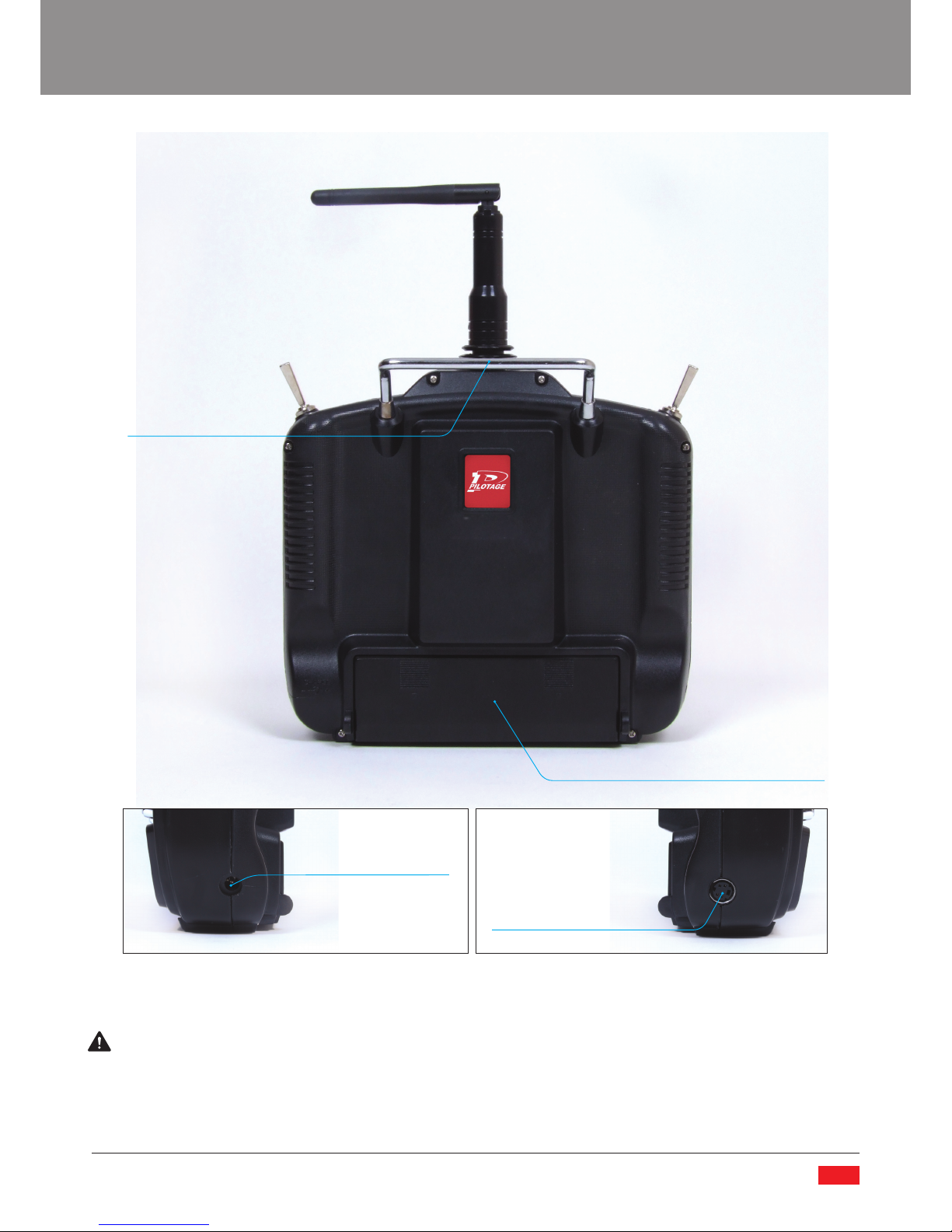
3. Antenna: The antenna transmits control signals to the model. Ensure that the antenna is in the upright/vertical position,
perpendicular to the top of the Tx prior to turning on the Tx and model.
4. Battery Power Indicator: The Battery Power Indicator displays 3 colors: red, yellow, and green. When 2 green LEDs are
illuminated this indicates that the batteries in the Tx are fully charged the Tx is safe to use to control your model. If only one
green LED is illuminated it means that your batteries are losing their power charge you should stop using your model at this
moment as they need to be replaced. If only the yellow LEDs are illuminated this indicates that the charge of the batteries
is low and should not be used to fly your model. If only red LEDs are illuminated it means that your batteries are exhausted
and the Transmitter is dangerous to use with your model. As battery power drops the control signal decreases which could
cause you to lose control of the model while in flight if attention is not paid to the charge status of the Tx batteries.
5. Throttle Trim Lever: When in the normal flight mode and this lever is shifted upwards, the amount of throttle and pitch of
the main rotor blades is increased, when moving this lever downwards the amount of throttle and pitch is decreased.
6. Yaw Trim Lever: Fine tunes the response to the rudder control commands (clockwise and counter clockwise rotation).
7. Pitch Trim Lever: Fine tunes the response to forward and backward control commands.
8. Roll Trim Lever: Fine tunes the response to lateral movement control commands.
ATTENTION: Every model requires trimming (fine tuning); likewise this process needs to be periodically repeated as the
construction of the model will change due to repeated use. If you need to constantly adjust the control sticks for the model to
hover in one place, trimming of your model is necessary. For in depth information on how to properly trim your model please
refer to the “Fine Tuning (Trimming) Your Model” section found later in this manual.
9. On/Off Switch: Turns your Tx “On” or “Off”, push up for “On”, push down for “Off”.
10. Flight Mode Toggle: This switch changes the flight mode of the model between Normal (NOR) and 3D. When the toggle is in
the position furthest away from you, this means that the model is in the Normal flight mode. The Normal flight mode is used
when taking off, landing and smooth flights along the horizontal plane. When the toggle is moved in the position towards
oneself the 3D flight mode is activated where the model will recieve more power from the throttle, the rotor pitch will be
greater and the model will handle more aggressively enabling it to perform 3D maneuvers.
ATTENTION!!! When the 3D flight mode is engaged it is impossible to turn off the motor, it runs permanently. NEVER attach the
battery to the model when the Flight Mode Toggle is in the 3D position. It should always be in the position NOR when turning on
or connecting the battery to the model. Not doing so could cause damage or injury due to sudden startup of the engine.
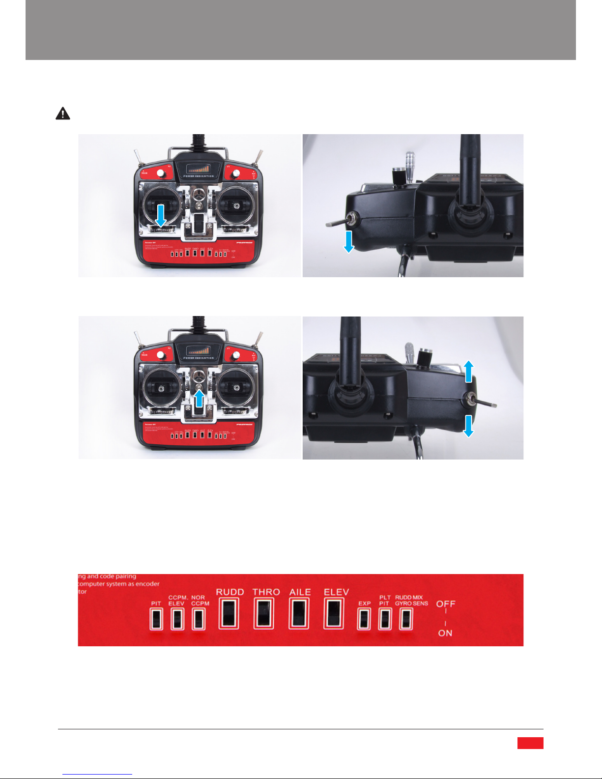
11. (V2) Exponentials/Pitch Limit (PIT)/Directional Mixer – This dial adjusts the aforementioned functions. The function that is
adjusted depends on the DIP switch settings.
12. (V1)Throttle Curve/Pitch Regulator (PIT)/Regulator Gyro Sensitivity – This dial adjusts the aforementioned fuctions. The
function adjusted depends on the DIP switch settings.
13. Gear Toggle Switch – This toggle switch acts as a safety toggle to prevent accidental motor turn on while setting up. When
the switch is towards oneself, the motor will not work.
6

Transmitter Back
If you install NiMH or NiCd batteries into your Tx you can use a battery charger with the appropriate size jack lead to connect to
the Tx. Note that any charger must have an output voltage of 12V DC and current from 50mA – 100mAh. DO NOT USE THE AC/DC
adaptor for the Li-Pol battery charger with this TX.
IMPORTANT!
Never connect a charger to this port when alkaline batteries are installed.
Simulator Connection Jack – This port is not active in the radio provided with this model. ATTENTION – do not attempt to
connect a simulator to this jack. Attempting to connect a simulator to this port may damage the electronics of the transmitter.
Carrying Handel
Charging Jack Simulator
Connection
Jack
(not active)
Battery Compartment
www.pilotage-rc.com
7

Tx Battery Installation
Ensure that the On/Off switch is in the “Off” position. Remove the battery cover by pressing down on the hatch and moving the
hatch away from the casing. Remove the battery cassette from the Tx.
Install 8pcs AA batteries into the battery cassette as illustrated. Please note the polarity markings (+ and -), and follow them
when installing the batteries. Please ensure that you install fresh batteries. Do not mix old and new batteries. Batteries may leak if
attention is not paid to these precautions.
When placing the cassette back into the Tx casing, do not force the battery output lead into the socket. It will only fit in one
direction. If it does not slide into the socket easily, check that the lead is correctly positioned and try again. If the lead is installed
incorrectly you risk reversing the polarity of the connection which may damage your Tx or cause a fire hazard.
Once the batteries have been properly installed close the battery hatch, and set aside the Tx for later use.
8

Turning on the Tx
ATTENTION! The Tx of this model includes a safety feature to prevent an accidental start of the motor. Please carefully review the
flowing instructions.
1. Move the Throttle/Blade Pitch stick to the lowest setting (all the way down).
Double check that the Flight Mode Toggle is set at NOR.
2. Turn the Tx on.
3. Remove the motor cut safety:
a. If the GEAR toggle switch is in the up position (closest to you) remove the safety by switching it to the down (further
away from yourself) position.
b. If the GEAR toggle switch is in the down position, remove the safety by switching the toggle up and then back to the
down position.
c. After the safety is removed the motor is now activated and any throttle inputs will cause the motor to turn the rotor
blades.
Changing and Default DIP Switch Positions
Below is listed the name and default setting of the dip switches on the Tx. Changing the dip switch settings to any other
configuration will cause the model to behave in a unpredictable or strange manner. This could lead to the model becoming
damaged or personal injury.
The dip switch settings are set at the factory by a qualified specialist. We firmly suggest that any changes to the dip switch
settings are done by an experienced modeler or service center technician.
1 2 3 4 5 6 7 8 9 10
www.pilotage-rc.com
9

Dip Switch Function Setting
1. PIT Reverse rotor pitch servo ON
2. CCPM/ELEV Reverse pitch ССРМ OFF
3. NOR CCPM Type of swashplate motion system NOR/CCPM ON
4. RUDD Reverse Yaw OFF
5. THRO Reverse Throttle OFF
6. AILE Reverse model pitch servo ON
7. ELEV Reverse roll ON
8. ЕХP Exponents OFF
9. PLT PIT Adjustment and lock for regulating the main rotor pitch travel OFF
10. RUDD MIX /GYRO SENS Heading Mixer/Gyro Sensitivity Switch OFF
Programming your Tx
1. Choice of CCPM (Cyclic/Collective Pitch Mixing) or normal swashplate control
This model uses a CCPM regime to control the swashplate. The DIP switch on slot #3 should be in the on position. If you use the
Tx for use with another model at some time which does not use CCPM you should then switch the dip switch in slot #3 to off.
2. Adjustment and Lock for regulating the main rotor pitch travel (DIP switch #9)
The Tx for this model allows one to adjust the servo travel of the servos that regulate the pitch of the main blades. It also allows
you to correct the angle of the blades. Do so as follows:
ATTENTION!!!!
Prior to adjusting the main blade pitch it is ESSENTIAL to disconnect the motor from the ESC prior to proceeding furhter!!!
A. Turn the Tx on. Remove the motor cut feature
using the GEAR toggle. Turn the dials V2 and V1 to
the center position (marks facing up). Make sure
that the DIP switch #9 is on the ON position.
B. When rotating V1 counterclockwise the lowest
pitch point of the main rotor becomes lower. When
rotating V1 clockwise the lowest pitch point of the
main rotor becomes higher.
C. When rotating V2 clockwise the servo travel (the
amount the pitch is adjustable) increases.When
rotating V2 counterclockwise the servo travel (the
amount the pitch is adjustable) decreases.
D. After adjusting the pitch settings lock them into
place by moving the DIP switch #9 to the off
position.
3. Heading Mixer/Gyro Sensitivity Switch (DIP
switch #10)
A. Turn the dials V2 and V1 to the center position (marks facing up). Make sure that the DIP switch #10 is on the ON position.
B. Dial V2 manages the function that regulates the heading that the model maintains and adjusts the sensitive of how the tail
rotor reacts to commands to change the models course. When V2 is in the central position this means that the mixer value is
set at 40%. When moving the dial clockwise you can increase the value up to 80%, and when rotating in a counterclockwise
direction you can reduce the mixing function to 0%.
10

C. The Dial V1 adjusts how sensitive the Gyro is. When the dial is in its central position the gyro setting is at 0. When
turning the dial in a counterclockwise direction the gyro works in the Normal regime decreasing the heading hold up to
-100%. When tuning the V1 dial to the right the heading hold function is increased up to 100%. We recommend that for
normal flight one should use the gyro sensitivity at about 70-80% and for 3D flight from 60% to 70%. For any flight it is
recommended to use the heading hold function.
D. After adjusting the pitch settings lock them into place by moving the DIP switch #10 to the off position.
4.0 Throttle curve and Exponential Throws. (DIP switch #8)
Turn the dials V2 and V1 to the center position (marks facing up). Make sure that the DIP switch #8 is on the ON position.
A. Adjusting the Throttle Curve while in “normal flight mode”.
Ensure that the toggle switch is in the NOR (down) position. If you turn the V1 dial in a clockwise direction the throttle curve
will move upwards to 80% as illustrated. If you turn the V1 dial in a counterclockwise direction, the throttle curve will drop
to 40% as illustrated. When the V1 dial is in the middle, the throttle curve is a straight line.
B. Adjusting the Throttle Curve while in “3D flight mode”
Move the flight mode toggle to the 3D (up) position. When moving the V1 dial in a clockwise direction the throttle curve
moves upwards to 80% as illustrated. When moving the V1 dial in a counterclockwise direction, the curve will move
downward to 40% as illustrated. When the dial is in its central position the curve throttle curve will be maintained at 60% as
noted.
C. Exponential Throws
When the V2 dial is in the central position the exponential throws of the throttle curve will be as illustrated in figure 1. When
rotating the V2 dial clockwise the exponential throws on the throttle will adjust to the shape as illustrated in figure 2. When
the V2 dial is rotated counter clockwise the exponential will adjust as illustrated in figure 3. Once the throttle exponentials
have been set move the DIP switch #8 to the off position.
fig. 1 fig. 2 fig. 3
www.pilotage-rc.com
11

5. Receiver connection layout
ELEV
AILE
THRO
RUDD
GEAR
AUX1
AUX2
BATT
This slot is used for the pitch/elevator servo (the servo in front of the swashplate)
This slot is used for the roll/aileron aervo (the servo to the left of the swashplate if viewing the model from tail to front.
This connects to the BEC output from the ESC to the receiver
This slot is used to connect to the gyro (the servo connected to the gyro and the gyro connects to the Rx)
Not used
Connects to the pitch servo (this servo is to the right of the swashplate if viewing the model from the tail to the front)
Connects to the gyro sensitivity lead
Not used
Antenna
ELEV – Pitch/Elevator
AILE – Roll Servo/Aileron
THRO - Throttle
RUDD – Yaw/Rudder
GEAR – Extra Channel
AUX1 –Pitch
AUX2 – Gyro Sensitivity
BATT – Battery
Receiver
12

GRYO OVERVIEW
This component is an electronic gyroscope with a tail boom heading hold function designed for use on radio control model
helicopters.
Technical Specications:
Size: 20x20x10mm/.8”x.8”x.4”
Weight: 5.7g/.2oz
Operational Voltage: 4.8-6V
Current: 15mA (5V)
Connecting the Gryo with the Rx
1. Insert the cable made of 3 wires into the Rudder (RUD) channel on your Rx. Then connect the wire that allows you to adjust
the sensitivity of the gyro to the auxiliary (AUX) channel on the Rx.
2. Turn your Tx on and supply power to your Rx. Set your rudder trimmer in the central position.
3. At the moment of start up when the LED on the gyro illuminates red or flashes blue, refrain from moving the gryo or model
until the LED on the gryo emits a solid blue light. If the gyro is moved while it is initializing it will fail to properly operate.
4. Using your Tx, activate the gyro’s heading hold function. Maintain flight at a low altitude and check the model’s
performance. If the tail of the model regularly drifts from one side to another adjust this by using the Tx rudder trimmer;
likewise check that the rudder servo takes up the same neutral position while in heading hold mode and in normal mode. If
necessary land the model and adjust the gyro sensitivity using the proper auxiliary channel trimmer as specified in your Rx
instruction manual.
5. If the model constantly drifts to one side or the other compensate for the drifting by adjusting the length of the pushrod
that goes to the tail rotor.
www.pilotage-rc.com
13

ELECTRONIC SPEED CONTROLLER ESC OVERVIEW
This model is equipped with an 18А ESC designed to power brushless motors.
This ESC is equipped with safety functions that will ensure a long service life of your helicopter. It has a very soft start to prevent
damage to the gears in the model. It will cut off if the current exceeds acceptable parameters. The ESC will reduce the power if
the temperature of the ESC rises above 100°C. In order to reverse the rotation direction of the motor one needs only to switch 2
of the three wires that connect the motor to the ESC.
ATTENTION!
1. This ESC is pre programmed at the factory and specially matched to provide optimal performance for your model. Only
an experienced and qualified modeler or a certified service center specialist should make any adjustments to the factory
default settings
2. Do not connect this ESC to battery configurations that are not recommended. This ESC will not support more than 6 NiCD/
NiMH cells or 2 Li-Pol cells. Doing so will damage your ESC.
3. The BEC of this ESC will not support more than 4 micro servos. Connecting more than 4 micro servos to a model used with
this ESC will burn the BEC in this ESC.
4. When connecting batteries to the ESC always make sure that the polarity of the connection is correct. Not following the
polarity of the connection will burn the components of your ESC and may lead to causing a fire hazard.
ESC Technical Specications
Size: 48x23x7mm /1.9”x.9”x.3”
Weight: 21g /.7oz
Max Current: 18A
Batteries: 6NiCD/NiMH or 2S Li-Pol only
BEC: will not support more than 4 micro servos
CHARGING THE LIPOL BATTERY
This model is comes with a Pilotage Electronics Simplex-3 2 & 3 Cell AC Mains Li-Pol Charger. This charger has been engineered
and designed to fulfill the needs of radio control modeling enthusiasts. This charger has been designed to offer an affordable yet
safe means of charging 2 and 3 cell battery packs. Some of the notable features of this item are:
• LEDs show charging status of individual cells
• Input current from 110-240V50/60hz
• Easy and intuitive to use
• Safe balance charging
• Automatic charge detection and cut off
14

This charger is suitable for novices and expert modelers alike. Please keep in mind that this product is not a toy. It is a battery
charger, designed for use exclusively with Li-Pol batteries and draws current form AC mains.
We hope that this product will serve you for years to come. Due to the sophisticated technical nature of this charger, it is
important that you carefully review all the below warnings, precautions, warranty terms and operational instructions thoroughly
to ensure safe use. Please retain the box and this manual for future reference.
Due to the fact that Pilotage is constantly improving the quality and functional characteristics of its products, some details,
colors, and functions may differ slightly from the images presented on the box and in the instructions
Precautionary Measures
ATTENTION! Please review throughly. Not fully compluing with these precautions may result in a fire hazard!!!!
• Do not use the charger inside of a vehicle.
• This charger is to be used only from AC mains. Do not use any other type of power source whenusing this charger.
• Never leave this charger to charge batteries unattended.
• This charger is designed only to be used with li-pol batteries. Never attempt to charge any other type of battery chemistry
with this charger..
• This charger is designed only to charge 2S and 3S packs. Never attempt to charge different cell configurations with this
charger.
• Never attempt to charge a battery pack if it appears to be damaged.
• This charger is designed to only charge one pack at a time. NEVER ATTEMPT to charge 2 packs simultaneously.
• If the battery cell heats up rapidly or expands, cease charging immediately and do not use the battery.
• Do not charge when the ambient temperature is extremely high.
• Ensure that the charging battery has been connected with the proper (+-) polarity.
• Ensure that the battery has had a chance to cool prior to recharging, as cells may heat up significantly when discharged at
high current rates.
• Ensure that the charger and battery pack have access to fresh air for cooling.
• Never cover the charger with clothing, pillows or any other loose item while the charger is connected to a power source.
• When charging batteries with this charger, do so in a dry, cool place away from flammable and combustible materials.
• Never store or use the charger in direct sunlight.
• Never expose this charger to any form of moisture. If the charger gets wet, cease from using it to prevent short-circuiting.
• After charging a battery cell, always disconnect the battery from the charger. Never store battery cells when connected to
the charger.
• Never puncture a battery casing.
• Protect your batteries from jolts, bumps, or any other form of trauma.
• Should the battery leak fluid onto your skin, flush well with water and consult a medical professional immediately.
• After use, always disconnect the charger from the power source.
• Never disassemble the charger.
• Never use this charger if the case has been removed, or if the wire leads from the charger are fayed or bent.
• Never dispose of batteries or the charger in a fire.
www.pilotage-rc.com
15

ATTENTION
This charger is not suitable for individuals 14 years of age and under. Any use of this charger by minors should occur under the
close supervision of an adult.
This charger includes small pieces that may act as choking hazard. Use and store it well away from small children.
Charger Components
Product Overview
Technical Glossary
Please take the time to thoroughly review the below glossary of terms as this battery charger is sophisticated in nature and a
clear understanding of the notations and terms used in the contents therein is essential to guarantee long product life and safe
exploitation.
Amperes/Amps/A: Amperes is a standardized unit that classifies the discharge rate of current from the charger to the battery or
vice versa.
Mili-Amperes/mA: Mili-Amperes is standardized measure of current. One mili-ampere is 1/1000 of an A. Therefore, 1.5A
(Amperes) is the same as 1500mA (1.5x1000). Inversely 1000mA is equal to 1A (1000/1000).
mAh (Mili-Ampere hours): Mili-ampere hours is a measurement of storable energy capacity in a given battery cell equal to the
amount of discharge current that the cell can supply measured in mili-amperes over the course of an hour. For example a battery
cell with a capacity of 3000mAh can discharge energy constantly at 3000mA over the course of an hour.
Ah (Amp hours): Ampere hours is a measurement of storable energy capacity in a given battery
cell equal to the amount of discharge current that the cell can supply measured in Amperes over the course of an hour. For
example a battery cell with a capacity of 3Ah can discharge energy constantly at 3A over the course of an hour.
C: The term “C” relates to the capacity in Ah or mAh of a battery.
LiPo/Li-Pol: Lithium Polymer, Li-Pol battery cell.
C Rating: “C” Rating is a specific term that relates to the rate that a given battery cell can discharge its stored energy at. A cell
with a 1C rating and a capacity of 2000mAh can only safely provide discharge current at 2A. A similar cell with a “C” rating of 5Cs
can safely discharge the battery’s energy at 5 times the capacity. In this instance is at 10A. Keep in mind that as the discharge
rate increases the amount of time that the pack can provide energy decreases. Hence a battery that discharges at 1C will work
for one hour to completely discharge. Note however that Li-Pol batteries should never be discharged under 3V per cell; meaning
that when used it should only be discharged for approximately 40minutes at this rate until the pack reaches 3V per cell. Likewise,
when discharging a battery pack at 5C, the cell will be completely depleted in 12minutes.
Pilotage Simplex 3
Li-Pol Charger
AC Mains Adaptor Cord Balancer Adaptor Cord (2pcs)
AC Mains Adaptor Cord
AC Mains Adaptor
Cord Socket
Cooling Vent
3 Charge Status LEDs
2 Cell Charge Connection Port
3 Cell Charge Connection Port
16

nC: The current of fully charging or discharging a battery pack in 1/n hour. For example, for 4000mAh battery pack, 1C means 4A,
2C means 8A, etc.
nS: A battery with n cells in series connection. For example, a 2s Li-Pol battery pack has the voltage of 7.4V (3.7x2=7.4V).
Technical Specications
Input Voltage:
Charge Current:
Supported Battery Chemistries:
110-240V AC 50/60Hz
650mA x 3, non adjustable
Li-Pol
Cells Supported:
Size:
Weight:
2S – 3S Li-Pol
99x58x32.5mm/3.9’’x2.3’’x1.3’’
165g/5.82oz
Determining Battery Type and Specications
Prior to connecting any battery to your Pilotage Electronics Simplex-3 it is essential that you determine the type of battery and its
specifications prior to charging it. Required information about your battery pack can be determined by examining the label and
any instructions that might accompany the battery pack.
This charger is designed to charge ONLY Lithium Polymer (Li-Pol) battery packs of 2S-3S cells. If you determine that the battery
pack that you wish to charge has over 3 cells in the pack or is not a Li-Pol pack DO NOT attempt to use this charger.
Using the Charger
Connect the charger to a power source
1. Insert the AC mains adaptor cord into the corresponding socket on the charger.
2. Plug the AC mains adaptor cord into an electrical socket in the wall.
Connect the battery to the charger:
1. The battery on hand will connect to the charger through its balance connector, the larger socket is exclusively for 3S
batteries, and the smaller socket is exclusively for 2S batteries.
2. Note that the battery will only slide into the slot in one way. Do not force the connection.
3. If the battery does not connect directly to the charger, use the included adaptor cable to make the required connection.
Please make sure the black wire of the battery balancer connector matches the black wire of the adaptor cable.
4. Once the battery is connected to the charger, it will automatically begin charging.
IMPORTANT!!!!!!:
Some batteries have the same balance connector for 3S and 2S batteries. The size difference is apparent. If your battery is of a 2S
configuration but uses a 3S connector, it is safe to plug this 2S cell into the 3S slot on the charger. The charger will only charge
2 cells independently. DO NOT HOWEVER connect one 2S cell to the charger and another 2S cell to the charger through the 3S
connector port. THIS CHARGER ONLY CHARGES ONE PACK AT A TIME!!!!
www.pilotage-rc.com
17

Charging/LED Status
This charger has 3 LED lights on the charger that indicate its status.
Orange – Power On
When the charger is connected to the AC mains all three lights will illuminate orange for 2
seconds indicating that the charger is receiving power and is properly connected. After the
Orange LEDs illuminate, they will all change to green.
Green – Stand By
Once the power has been turned on and the LEDs will change from orange to green, this
indicates that the charger is ready to connect to the battery and start the charging process.
Red – Charging
Once the battery to be charged has been properly connected to the charger, the charger will
switch from standby (green) to the charging function (Red). This charger checks and charges
each individual cell in the pack to 4.2V at a rate of 650mAh, ensuring that the pack is balanced
and will not encounter a voltage drop between the cells.
If a 2S cell battery is connected to the charger, LED Cell 1 and Cell 2 will turn red as these ports
are actively charging. LED Cell 3 will remain green in standby mode.
If a 3S cell is connected to the charger all 3 LEDs will change from green to red.
Green – Fully Charged
As each cell is charged up to 4.2V the red LED will revert to green. When you see that the all
3 LEDs are green and the battery is connected to the charger, you know that the charging
process is complete.
Disconnecting the Battery
Once the charging process is complete unplug the charger from the electrical socket.
After the charger is turned off, disconnect the battery from the charger. NOTE: Disconnect the battery from the charger by
pulling on the hard plastic battery connector casing itself, and not on the wires that lead to the battery. Doing so could pull the
wires loose from the battery.
WARNING!
NEVER leave the charger unattended when either connected to a battery or connected to an electrical socket.
18

HELICOPTER OVERVIEW
10. Servo
11. Tail Rotor Belt
12. Motor
13. Receiver
14. Landing Skid
15. Main Gear
16. Gyro
17. ESC
18. Battery Input Socket
1. Tail Rotor
2. Tail Gearbox
3. Tail Boom
4. Flybar
5. Swashplate
6. Main Rotor Shaft
7. Main Rotor Blades
8. Battery Mount
9. Canopy
1
2
4
16
17
6
57
9
8
18
12
14
15
13
11
10
3
www.pilotage-rc.com
19
Table of contents
Languages:
Other PILOTAGE Toy manuals
Popular Toy manuals by other brands

Top Flite
Top Flite Cessna 182 ARF user guide

Ofna Racing
Ofna Racing dominator monster pirate instruction manual

Mattel
Mattel Barbie BDG50 instructions

Mattel
Mattel Disney PIXAR Cars 2 V9861 instructions

Dasarobot
Dasarobot Genibo-QD user manual

Pilot Communications
Pilot Communications 30cc Assembly manual