PIMAX PX 4718.2099 User manual

advised position for the switches installation
position conseillee pour l’installation des boutons
emfohlene lage für den schalterneinbau
posicion aconsejada para la instalacion de los pulsadores
posição para a inslalação dos interruptores
posizione consigliata per l’istallazione dei pulsanti
Skoda Fabia (1999>3/2007)
Versioni / Models: Classic [Solo motore
per elettrificazione alzacristalli manuali
originali / Only motor for replacement
of original manual window regulators
Skoda Combi (1999>)
Versioni / Models: Classic [Solo motore
per elettrificazione alzacristalli manuali
originali / Only motor for replacement
of original manual window regulators
Skoda Station Wagon (1999>)
Versioni / Models: Classic [Solo motore
per elettrificazione alzacristalli manuali
originali / Only motor for replacement
of original manual window regulators
Power Windows
Leve-glace Electrique
Elektrische Fensterheber
Elevalunas Electricos
Dê Poder a Janelas
Alzacristalli Elettrici
PX 4718.2099

SK18
left door - portière gauche - linke tür - puerta lado izquierdo - porta esquerda - porta lato sinistro
THIS INSTALLATION INSTRUCTION IS FOR BOTH LEFT AND RIGHT SIDE.
CETTE INSTRUCTION DE MONTAGE EST POUR LES DEUX COTES DROIT ET GAUCHE.
DIESE MONTAGE-ANLEITUNG IST FÜR DIE BEIDE LINKE UND RECHTE SEITE.
ESTA INSTRUCCION DE MONTAJE ES PARA LOS DOS LADOS IZQUIERDO Y DERECHO.
LA PRESENTE ISTRUZIONE VALE SIA PER IL LATO SINISTRO CHE PER IL LATO DESTRO.

SK18


THIS INSTALLATION INSTRUCTION IS FOR BOTH LEFT AND RIGHT SIDE.
CETTE INSTRUCTION DE MONTAGE EST POUR LES DEUX COTES DROIT ET GAUCHE.
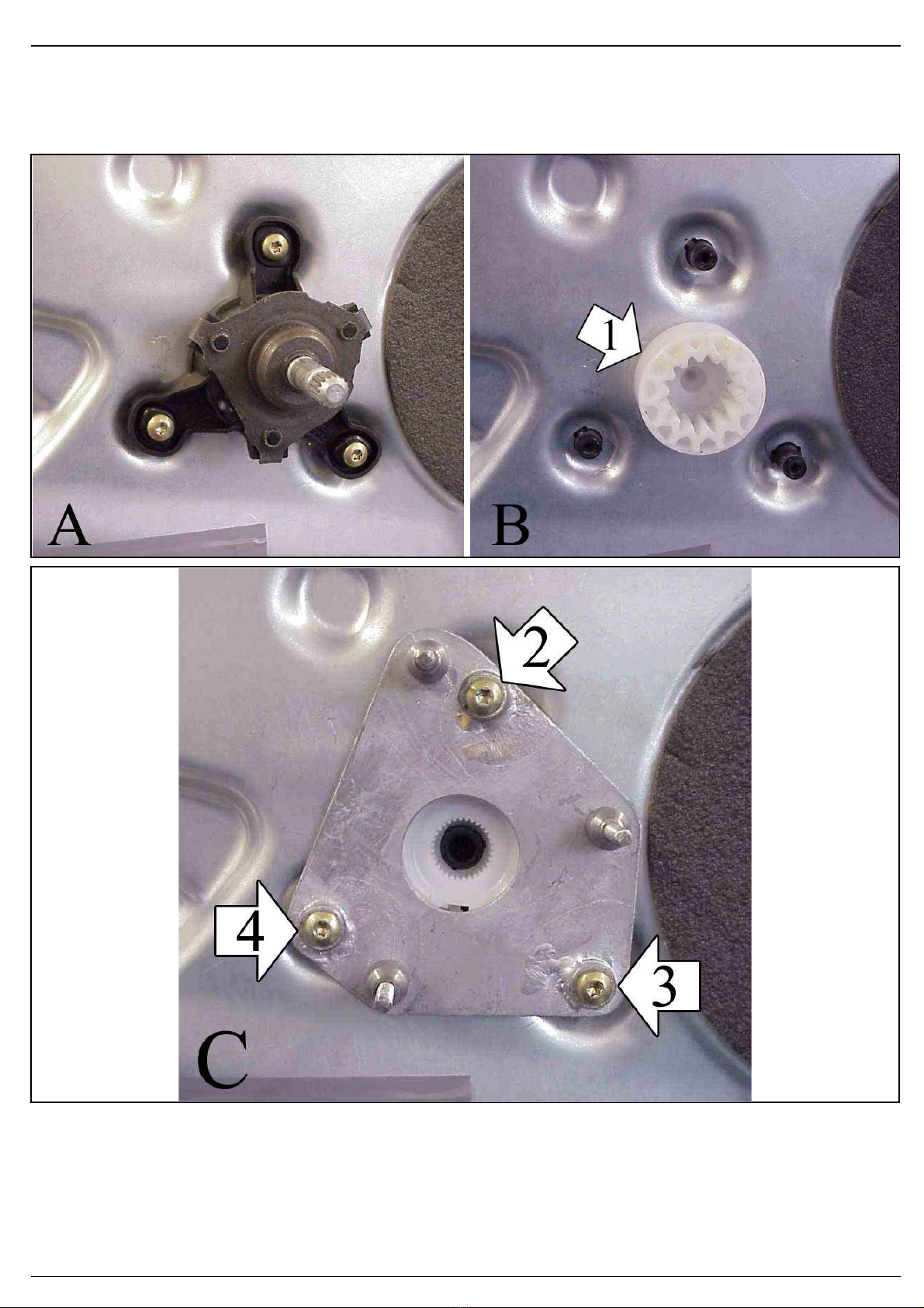
B) Remove the three screws from the manual windows regulator and remove the piece n° 1 (photos A-B). Save the screws for later.
C) Place the plate as in the photo C and fix it with the three screws previously removed at position 2, 3 and 4.
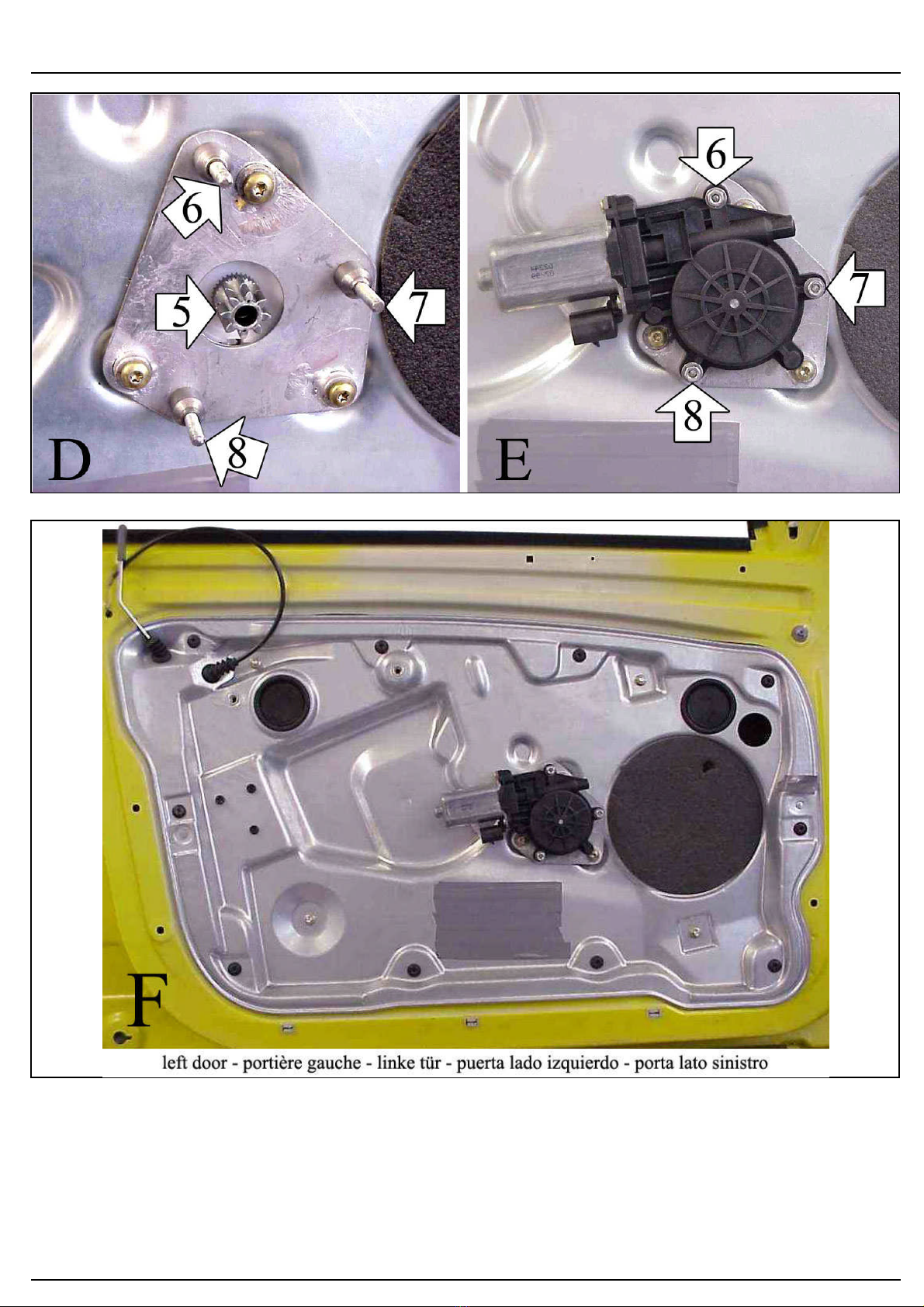
D) Insert the motor pinion (positions 5) (photo D) in the housing of the plastic piece n° 1 previously removed. Place the motor as in the
photo E and fix it into positions 6, 7 and 8.
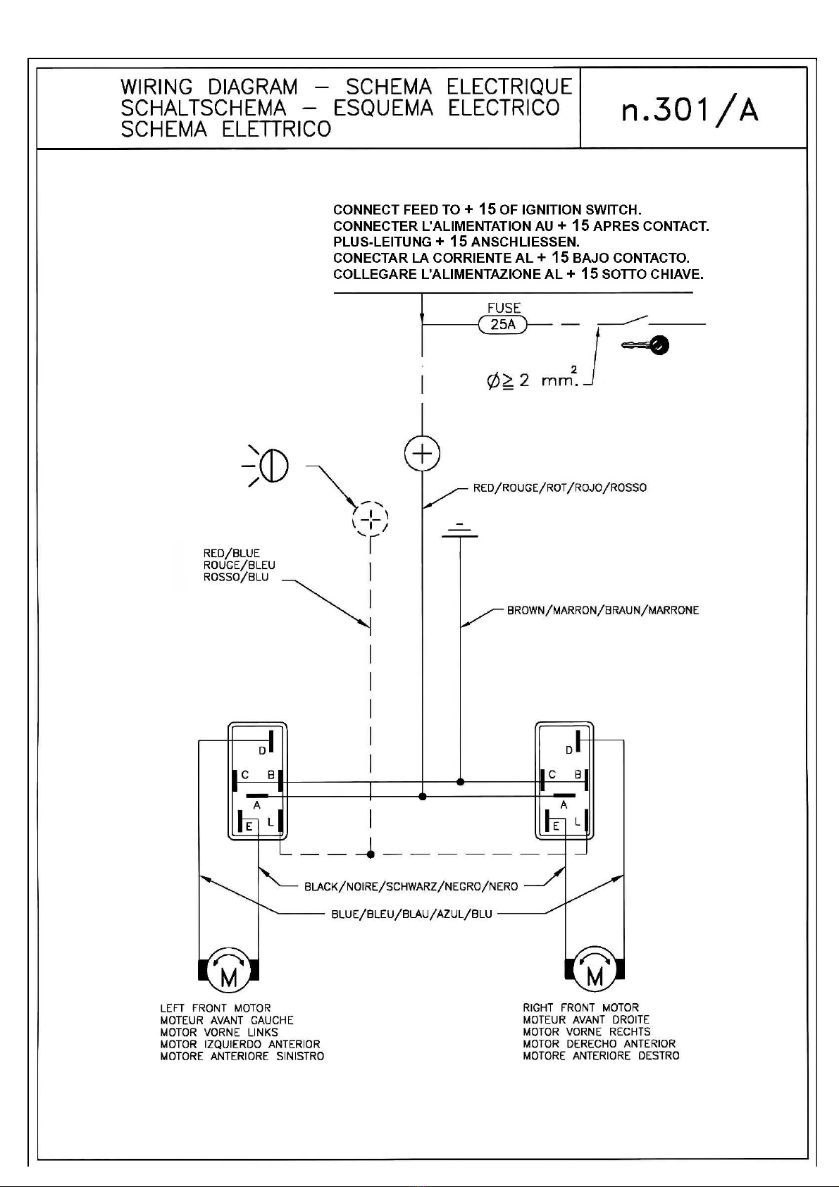
E) Wire as per wiring diagram. Check correct window operation before re-fitting door trim.
F) For the replacement of the spare-part, in case the motor connector is not compatible with the original one, make the wiring connection
with the cable supplied.
A) AVANT DE PROCEDER AVEC LE DESASSEMBLAGE DE LA PORTE, POSITIONNER LA VITRE A LA MOITIE DE LA COURSE.
Demonter le panneau de la porte.
B) Desserrer les trois vis du leve-vitre manuel et detacher la piece 1 (photos A-B). Conserver les vis que Vous devrez recuperer.
C) Placer la plaque comme sur la photo C et le fixer avec les trois vis precedemment demontees sur les points 2, 3 et 4.
D) Inserer le pignon du moteur (points 5) (photo D) dans la siege de la piece en plastique 1 precedemment demontee. Placer le moteur
comme sur la photo E et le fixer sur le points 6, 7 et 8.
E) Effectuer le liaisons electriques. Verifier le bon fonctionnement de la vitre avant de remonter le panneau de la porte.
F) Pour le remplacement du piece detache, quand le connecteur du moteur n'est pas compatible avec le connecteur d'origine, effectuer
les liaisons electriques avec le cable fourni.
DIESE MONTAGE-ANLEITUNG IST FÜR DIE BEIDE LINKE UND RECHTE SEITE.
A) BEVOR DIE TÜRVERKLEIDUNG ZU DEMONTIEREN, MÜSS DAS FENSTER HALB-LAUF SEIN.
Demontieren Sie die Türverkleidung.
B) Demontieren Sie die drei Schrauben aus dem manuellen Fensterheber und entfernen Sie das Stück 1 (Abb. A-B). Heben Sie die
Schrauben für später auf.
C) Positionieren Sie die Platte wie in der Abbildung C und befestigen Sie ihn mit den drei vorher demontierten Schrauben an den Punkten
2, 3 und 4.
D) Setzen Sie das Motor-Ritzel (Punkt 5) (Abb. D) an der Stelle von dem vorher demontierten Kunststoffstück 1 ein. Positionieren Sie
den Motor wie in der Abbildung E und befestigen Sie ihn an den Punkten 6, 7 und 8.
E) Verlegen Sie die elektrische Verkabelung. Vor der endgültigen Fertigstellung überprüfen Sie die einwandfreie Funktion des elektrischen
Fensterhebers.
F) Um den Ersatzteil zu ersetzen, wenn der Motor-Verbinder nicht kompatibel mit den Original-Verbinder ist, verlegen sie die elektrische
Verkabelung mit dem beigefugten Kabel.
ESTA INSTRUCCION DE MONTAJE ES PARA LOS DOS LADOS IZQUIERDO Y DERECHO.
A) ANTES DE DESMONTAR LA PUERTA, BAJAR EL CRISTAL HASTA MITAD CARRERA.
Desmontar la plancha de la puerta.
B) Desatornillar los tres tornillos del elevalunas manual y remover la pieza 1 (foto A-B). Conservar los tornillos para despues.
C) Colocar la placa como en la foto C y fijarla mediante los tres tornillos 2, 3 y 4 antecedentemente desmontados.
D) Introducir el piñon del motor (tornillo 5) (foto D) en el alojamento de la pieza de plastico 1 antecedentemente desmontada. Colocar el
motor como en el dibujo E y fijarlo en los puntos 6, 7 y 8.
E) Efectuar las conexiones eléctricas. Controlar el funcionamiento del cristal antes de volver a montar el panel de la puerta.
F) Para la substitucion del repuesto, caso que el conectador del motor no es compatible con el conectador original, hacer las conexiones
electricas con el cable del kit.
ESPAÑOL
DEUTSCH
FRANÇAIS
ENGLISH
ENGLISH
FRANÇAIS
DEUTSCH
DEUTSCH
ESPAÑOL
ESPAÑOL
ITALIANO
ENGLISH
FRANÇAIS
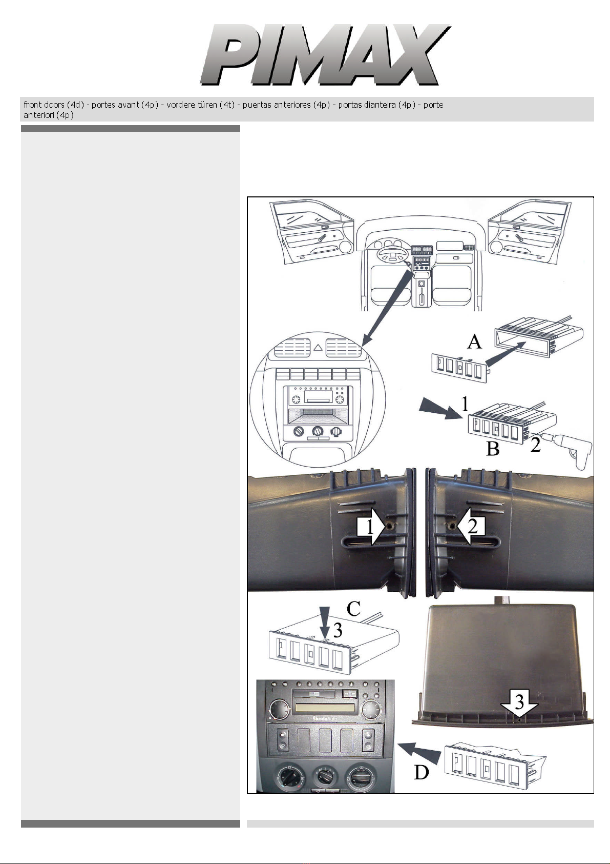
A) BEFORE STARTING TO DISASSEMBLE THE DOOR, POSITION THE GLASS AT HALF TRAVEL.
Disassemble door panel.
31-01-2012
LA PRESENTE ISTRUZIONE VALE SIA PER IL LATO SINISTRO CHE PER IL LATO DESTRO.
A) PRIMA DI PROCEDERE ALLO SMONTAGGIO DELLA PORTA, POSIZIONARE IL VETRO A META' CORSA.
Smontare il pannello di rivestimento della portiera.
B) Smontare le tre viti del meccanismo manuale ed asportare il particolare n° 1 (foto A-B). Conservare le viti che verranno riutilizzate.
C) Posizionare la piastra come da foto C e fissarla mediante le tre viti precedentemente smontate nei punti n° 2, 3 e 4.
E) Eseguire i collegamenti elettrici. Controllare il funzionamento dei cristalli prima di rimontare il pannello portiera.
F) Per la sostituzione del ricambio, nel caso il connettore motore non fosse compatibile con il connettore originale, effettuare il
collegamento elettrico mediante il cavo in dotazione.
ITALIANO
ITALIANO
D) Introdurre il pignone del motore (punto n° 5) (foto D) nella sede del particolare in plastica n° 1 precedentemente smontato.
Posizionare il motore come da foto E e fissarlo nei punti n° 6, 7 e 8.

THIS INSTALLATION INSTRUCTION IS FOR BOTH LEFT AND RIGHT SIDE.
CETTE INSTRUCTION DE MONTAGE EST POUR LES DEUX COTES DROIT ET GAUCHE.
Remove the glove box as shown in the drawing (point A).
Insert the switch mounting; fit it and drill into positions 1 and 2 (Ø 2) through the locating wings (point B).
Fix the mounting with the screws supplied into positions 1 and 2.
Reverse the glove box and in the lower part drill into position 3 (Ø 2) (point C).
Fix the mounting with the screw supplied into position 3.
Drill at the bottom of the glove box an enough big hole for the passing of the wiring.
Replace the glove box and connect the switches (point D).
SK18
POSITION CONSEILLEE POUR L'INSTALLATION DES BOUTONS.
Demonter le porte-objet comme indique sur le dessin ci-joint (point A).
Inserer le support des boutons; positionner correctement le support et ensuite percer les trous sur les points 1 et 2 (Ø 2) en
correspondance des languettes du support (point B).
Fixer le support avec les vis fournies sur les points 1 et 2.
Renverser le porte-objet et dans la partie inferieure percer le trou sur le point 3 (Ø 2) (point C).
Fixer le support avec la vis fournie sur le point 3.
Percer un trou au bas du porte-objet pour le passage du cablage.
Remonter le porte-objet et effectuer la connexion des boutons (point D).
DIESE MONTAGE-ANLEITUNG IST FÜR DIE BEIDE LINKE UND RECHTE SEITE.
SK18
EMPFOHLENE LAGE FÜR DEN SCHALTERNEINBAU.
Demontieren Sie das Ablagefach in der Mittelkonsole (Abb. A).
Stecken Sie den Schalterrahmen. Nachdem der Schalterrahmen genau eingepaßt ist, bohren Sie Löcher an den Punkten 1 und 2 mit 2
mm. Ø über den Halteklammern (Abb. B).
Befestigen Sie den Schalterrahmen mit den beigefügten Schrauben an den Punkten 1 und 2.
Umkehren Sie die Ablageflach und nach unten bohren Sie ein Loch im Punkt 3 mit 2 mm Ø (Abb. C).
Befestigen Sie den Schalterrahmen mit der beigefügten Schraube im Punkt 3.
Bohren Sie ein Loch am Boden der Ablagefach für die Verkabelung.
Montieren Sie wieder die Ablagefach und verbinden Sie den Schaltern (Abb. D).
ESTA INSTRUCCION DE MONTAJE ES PARA LOS DOS LADOS IZQUIERDO Y DERECHO.
SK18
POSICION ACONSEJADA PARA LA INSTALACION DE LOS PULSADORES.
Desmontar la consóla (fig. A).
Introducir el soporte porta-interruptores. Una vez bien encajado, praticar un taladro en los puntos 1 y 2 de 2 mm. en concordancia con
las lengüetas de la parte superior. ( fig.B ).
Fijar el soporte con los tornillos suministrados en los puntos 1 y 2.
Volcar la consóla y en la parte inferior praticar un taladro en el punto 3 (Ø 2) (Fig. C).
Fijar el soporte con el tornillo suministrado en el punto 3.
Praticar un taladro en el fondo de la consola para el pasaje del cableado.
Volver a montar la consola y proceder a la conexión eléctrica de los pulsadores (Fig. D).
LA PRESENTE ISTRUZIONE VALE SIA PER IL LATO SINISTRO CHE PER IL LATO DESTRO.
SK18
POSIZIONE CONSIGLIATA PER L'INSTALLAZIONE DEI PULSANTI.
Smontare il portaoggetti indicato nel disegno (punto A).
Inserire il supporto pulsanti; posizionarlo correttamente e quindi procedere a forare con punta Ø 2 nei punti n° 1 e 2 in corrispondenza
delle linguette del supporto (punto B).
Rovesciare il portaoggetti e nella parte inferiore praticare un foro con punta Ø 2 nel punto n° 3 (punto C).
Fissare il supporto con la vite fornita nel punto n° 3.
Praticare un foro di adeguate dimensioni sul fondo del portaoggetti per il passaggio del cablaggio.
Rimontare il portaoggetti e procedere al collegamento dei pulsanti (punto D).
ITALIANO
ESPAÑOL
DEUTSCH
FRANÇAIS
ENGLISH
ENGLISH
FRANÇAIS
DEUTSCH
DEUTSCH
ESPAÑOL
ESPAÑOL
ITALIANO
ENGLISH
FRANÇAIS
SK18
ADVISED POSITION FOR THE SWITCHES INSTALLATION.
Fissare il supporto con le viti fornite nei punti n° 1 e 2.
31- 01- 2012SK18