Ping Communication RGW208EN User manual

Product Guide
for
Residential Gateway
RGW208EN
Version: 17th of March 2010
Page 1 of 92

1 Getting started 6
1.1 Troubleshooting 6
1.2 How to read the manual 6
2 Basic menu 7
2.1 Internet 7
2.1.1 Internet Connection Setup Wizard 7
2.1.2 Manual setup 10
2.1.2.1 Modes 10
2.1.2.2 Advanced 12
2.2 Network Settings 13
2.2.1 outer Settings 14
2.2.2 IP ( outing Information Protocol) 15
2.2.3 DHCP Server Settings 15
2.2.4 Add DHCP eservation 17
2.2.5 DHCP eservations list 18
2.2.6 Number of Dynamic DHCP Clients 19
2.3 Wireless settings 19
2.3.1 Manual Wireless Network Setup 20
2.3.1.1 Wireless Network Settings 20
2.3.1.2 Wireless Network 1 21
2.3.1.3 Wireless Network 2-4 22
2.3.2 Add Private Wireless Device Wizard 22
2.3.3 Add Guest Wireless Device Wizard 23
2.3.4 Wireless Network Setup Wizard 23
3 Advanced 24
3.1 irtual Server 24
3.1.1 Add/Edit Virtual Server 25
3.1.2 Virtual Servers List 25
3.2 Port Forwarding 25
3.2.1 Port forwarding ules 27
3.3 Special Applications 27
3.3.1 Add/Edit Special Applications ule 28
3.3.2 Special Applications ules List 28
3.4 Traffic Shaping 28
3.5 StreamEngine™ 30
3.5.1 StreamEngine™ Setup 30
3.5.2 Add/Edit StreamEngine™ ule 31
3.5.3 StreamEngine™ ules List 32
3.6 Routing 32
3.6.1 Add/ Edit oute 33
3.6.2 outes List 34
3.7 Access Control 34
3.7.1 Access Control 35
3.7.2 Policy Table 35
3.7.3 WEB Filter 35
Page 2 of 92

3.7.4 Add/Edit Web Site 36
3.7.5 Allowed Web Site List 37
3.8 MAC Address Filter 37
3.8.1 MAC Filtering Setup 37
3.8.2 Add/ Edit MAC Address 38
3.8.3 MAC Address List 38
3.9 Firewall 38
3.9.1 Firewall Settings 39
3.9.2 NAT Endpoint Filtering 39
3.9.3 Various 40
3.9.4 DMZ Host 40
3.9.5 Non-UDP/ TCP/ IMCP LAN Sessions 41
3.9.6 Application Level Gateway (ALG) Configuration 41
3.10 Inbound filter 43
3.10.1 Add/Edit Inbound Filter ule 44
3.10.2 Inbound Filter ules List 44
3.11 Advanced Wireless 44
3.12 WISH 47
3.12.1 Priority Classifiers 48
3.12.2 Add/Edit WISH ule 48
3.12.3 WISH ules 49
3.13 Wi-Fi Protected Setup 49
3.13.1 Wi-Fi Protected Setup 49
3.13.2 PIN Settings 49
3.14 Advanced Network 50
3.14.1 UPnP 50
3.14.2 PPPoE Pass Through 51
3.14.3 LAN Auto IP 51
3.15 LAN 51
3.15.1 VLAN Tagging 52
3.15.2 Internal Services 52
3.15.3 Custom VLANs 52
3.15.4 Default VLAN 52
3.15.5 VLAN to SSID mapping 53
3.16 Provisioning 53
3.16.1 Three provisioning protocols 54
4 VoIP 55
4.1 Line 1 55
4.1.1 SIP Settings 55
4.1.2 Codec Settings 56
4.1.3 DTMF Events 56
4.1.4 Dialplan Settings 57
4.1.5 Telephony Settings 57
4.2 Advanced 58
4.2.1 STUN Settings 58
4.2.2 User Agent Server Settings 59
4.2.3 NAT Ping Settings 59
4.2.4 VoIP QoS 60
Page 3 of 92

4.3 Regional Settings 60
4.3.1 egion 60
4.3.2 Analog Settings 61
4.3.3 ing tone 61
4.3.4 Call Event Tones 61
4.3.5 Help Tones 62
4.3.6 Advanced Audio 63
5 Tools 64
5.1 User 64
5.2 Admin 65
5.2.1 Admin Password 65
5.2.2 System name 65
5.2.3 Administration 65
5.3 Time 66
Time Configuration 66
Automatic Time Configuration 67
Set the Date and Time 67
5.4 Syslog 67
5.5 Email settings 68
5.5.1 Email Settings 69
Email Log When Full or on Schedule 70
5.6 System 70
5.7 Firmware 71
5.7.1 Firmware Information 72
5.7.2 Firmware Upgrade 72
5.8 Dynamic DNS 72
5.9 System Check 74
5.9.1 Ping Test 74
5.9.2 Ping esult 74
5.10 Schedules 75
5.10.1 Add/Edit Schedule ule 75
5.10.2 Schedule ules List 76
5.11 Bandwidth 76
5.12 Mirror 78
5.13 Console 79
6 Status 0
6.1 Device Info 80
6.1.1 General 80
6.1.2 WAN 80
6.1.3 LAN 82
6.1.4 VoIP Line Status 82
6.1.5 LAN Computers & IGMP Multicast memberships 82
6.2 Wireless 83
Page 4 of 92

6.3 Routing 83
6.4 Logs 84
6.4.1 Log Options 85
6.4.2 Log Details 85
6.5 Statistics 85
6.5.1 LAN Statistics 86
6.5.2 WAN Statistics 86
6.6 Internet Sessions 87
6.7 Firewall Holes 88
6.8 WISH Sessions 89
7 Help 92
Page 5 of 92

1 Getting started
The Configuration Interface can be accessed fro your Web browser. Open up your
Web browser and type http://192.168.176.1 in the address field and press Enter.
The Configuration Interface login screen will appear. By default, there is no
password. Click on the Log In button to access the Configuration ain screen.
1.1 Troubleshooting
Make sure your co puter is connected to LAN port on the device. Then open a
co and window and type ipconfig (Windows) or ifconfig (Linux/Mac). You should
then be able to read the IP address of the Default Gateway of the LAN connection on
your co puter (assu ing you only have one LAN network interface). If this IP
address do not appear, the co puter is not connected to the device. If it does
appear, use that address instead of 192.168.176.1 (assu ing it differ).
1.2 How to read the manual
This anual will go through all enus in an orderly fashion. Chapter 2 starts with
the first left enu ite (Basic) and the sub chapters covers the upper enu. Then if
you look up a certain chapter in this anual you can always know that the ain
chapter heading denotes the left enu choice and the sub chapter heading denotes
the upper enu choice.
Page 6 of 92

2 Basic menu
2.1 Internet
The Internet Connection screen contains the Internet Connection Wizard that assists
you in configuring the device to allow it to connect to the Internet, as well as the
Manual Internet Connection Options screen in which you can set up your Internet
connection anually.
2.1.1 Internet Connection Setup Wizard
The Internet Connection Setup Wizard will assist you with connecting the device to
the Internet. The step by step guide will pro pt you for the necessary infor ation to
get you connected. The Internet Connection Setup Wizard guides you through the
following basic router setup steps:
To begin, click on the Launch Internet Connection Setup Wizard button.
The Welco e screen appears, click Next to continue.
Note: The device is intelligent, and will in so e cases anage to connect to the
Internet auto atically. In this case the Wizard will report that a connection has been
established successfully, but will still let the user proceed through steps 1 and 2.
Step 1: Set Your Password pro pts you to enter a password for the Web-based
configuration interface. You can enter the password in the Verify Password pro pt.
Page 7 of 92

Step 2: Select Your Ti e Zone pro pts you to select your ti e zone fro the
pull-down enu.
Step 3: Configure Your Internet Connection. At this stage we assu e that the
device is not connected to the internet, otherwise the wizard would have skipped this
step. Still, there are possibilities if the connection type of your Internet Service
Provider (ISP) is known (or can be established).
If your ISP is listed in the drop-down enu (and you choose it) then the connection
type is chosen for you. Otherwise, specify the connection type anually.
Depending upon your Internet Service Provider or the type of connection you
selected in the previous step, one of five screens will appear. If you are unsure of
any of the infor ation, please contact your Internet Service Provider (ISP) for
details.
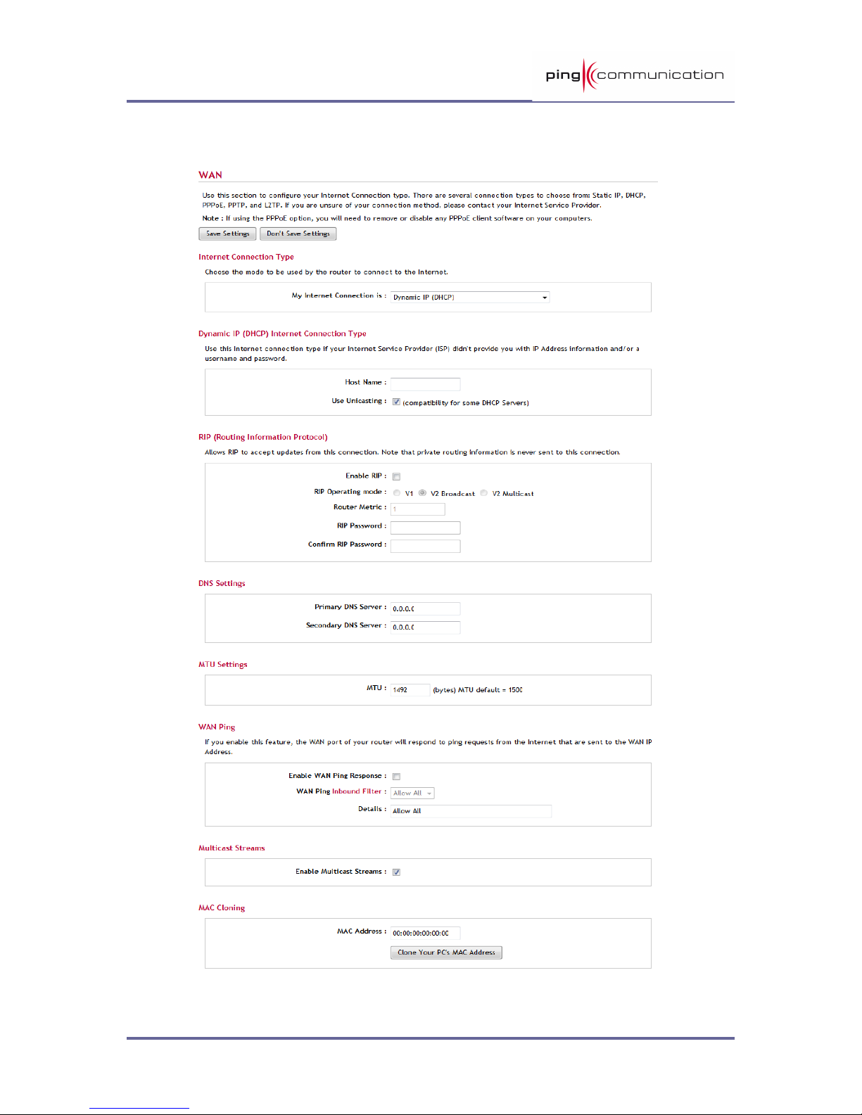
•DHCP Connection (Dyna ic IP Address). DHCP is a uch used
connection type. It should usually not require any setup on your behalf.
However, at this point we have an “unusual” situation (since you're reading
this). If you have put your device behind a cable ode 1 (a device which is
connected to a coax cable) there are so e things you could try:
•Try to restart that ode . Cancel this setup and try again.
•If you previously had equip ent (like your PC) connected to the cable
ode and actually had a working internet connection, you can try to
clone/copy the MAC address of that equip ent into this device. By
pressing the Clone Your PC’s MAC Address you will copy the MAC
address of the PC you’re connecting to this device. If, let’s say, you had a
router connected behind the cable ode , you could read MAC address
(usually printed underneath the router) and enter it anually. You can
always reverse this step later by entering the MAC address printed on this
device (the WAN MAC).
A last resort ay be to add a hostna e if that is provided by the ISP. This is
not very co on.
The settings for DNS could be left untouched, unless you have been able to
retrieve this infor ation fro the ISP. Usually (again) this infor ation is
auto atically populated when connecting on DHCP.
•Set Userna e and Password Connection (PPPoE) pro pts you to enter
your Userna e and Password. This infor ation ust be provided by the ISP
(typically in a welco e letter). You ust also verify the Password. If your ISP
requires a Service Na e entry, please enter it here. The default setup is to
get the IP address dyna ically. In so e cases the ISP has chosen to give you
a static IP. You can then choose the static radio button and enter the IP
address.
•Set Userna e and Password Connection (PPTP) pro pts you to enter
your PPTP IP Address, PPTP Subnet Mask, PPTP Gateway IP Address, PPTP
Server IP Address, Userna e, and Password. You ust also verify the
Password. This infor ation ust be provided by the ISP (typically in a
welco e letter).
1 A cable modem or any device which is not connecting on the IP layer. That excludes all DSL modems.
Page 8 of 92

•Set Userna e and Password Connection (L2TP) pro pts you to enter
your L2TP IP Address, L2TP Subnet Mask, L2TP Gateway IP Address, L2TP
Server IP Address, Userna e and Password. You ust also verify the
Password. This infor ation ust be provided by the ISP (typically in a
welco e letter).
•Set Static IP Address Connection pro pts you to enter the IP address,
Subnet Mask, Gateway Address, Pri ary and Secondary DNS address
infor ation. This infor ation ust be provided by the ISP (typically in a
welco e letter).
•Setup Co plete will appear after all of the settings have been entered. Click
Connect to save your settings and reboot the router.
Page 9 of 92

2.1.2 anual setup
2.1.2.1 Modes
Page 10 of 92

There are five connection odes to choose fro as shown below. If you are unsure
of your connection settings, contact your Internet Service Provider (ISP) and you can
enter the necessary infor ation on the Quick Installation Guide (QIG) or print this
page and write the settings for future reference.
Pri ary DNS Server: _____._____._____._____
Secondary DNS Server: _____._____._____._____
Static: Used when your ISP provides you a set IP address that does not change. The
IP infor ation is anually entered in your IP configuration settings.
IP Address: _____._____._____._____
Subnet Mask: _____._____._____._____
Def. Gateway: _____._____._____._____
DHCP: A ethod of connection where the ISP assigns your IP address when your
co puter requests one fro the ISP’s server. So e ISP’s require you to ake so e
settings on your side before your co puter can connect to the Internet.
Host Na e:_____________________
PPPoE: A ethod of connection that requires you to enter a Userna e and
Password (provided by your Internet Service Provider) to gain access to the
Internet.
Userna e: __________________
Password: __________________
Service Na e (Optional): __________________
PPTP: A ethod of connection that requires you to enter infor ation provided by
your Internet Service Provider to gain access to the Internet.
PPTP IP Address: _____._____._____._____
PPTP Subnet Mask: _____._____._____._____
PPTP Gateway IP Address: _____._____._____._____
PPTP Server IP Address: _____._____._____._____
Userna e: ______________________
Password: ______________________
L2TP: A ethod of connection that requires you to enter infor ation provided by
your Internet Service Provider to gain access to the Internet.
L2TP IP Address: _____._____._____._____
L2TP Subnet Mask: _____._____._____._____
L2TP Gateway IP Address: _____._____._____._____
L2TP Server IP Address: _____._____._____._____
Userna e: ______________________
Password: ______________________
All five odes have so e co on configuration options. The Pri ary and Secondary
DNS Server settings are required for Static configurations and optional for DHCP and
PPPoE configurations. The Advanced options on the following page can be odified
for any of the five connection odes. You should be able to get the Pri ary DNS
Page 11 of 92

and Secondary DNS Servers settings fro your router configuration settings, ISP,
or your network ad inistrator. Only the pri ary DNS server address is required,
though it is best to have both the pri ary and secondary addresses.
2.1.2.2 Advanced
The Advanced options apply to all WAN odes.
Use the Default MTU: This option is enabled by default allowing the router to select
the typical MTU settings for the selected WAN interface. If this option is unchecked,
the router will use the value assigned in the MTU field.
MTU: The MTU (Maxi u Trans ission Unit) is a para eter that deter ines the
largest packet size (in bytes) that the router will send to the WAN. If LAN devices
send larger packets, the router will break the into s aller packets. Ideally, you
should set this to atch the MTU of the connection to your ISP. Typical values are
1500 bytes for an Ethernet connection and 1492 bytes for a PPPoE connection. If the
router’s MTU is set too high, packets will be frag ented downstrea . If the router’s
MTU is set too low, the router will frag ent packets unnecessarily and in extre e
cases ay be unable to establish so e connections. In either case, network
perfor ance can suffer.
MAC Cloning Enabled: So e ISP’s ay check your co puter’s MAC address. Each
networking device has it’s own unique MAC address defined by the hardware
anufacturer. So e ISP’s record the MAC address of the network adapter in the
co puter used to initially connect to their service. The ISP will then only grant
Internet access to requests fro a co puter with this particular MAC address. The
device has a different MAC address than the co puter that initially connected to the
ISP. To resolve this proble , enable this option.
MAC Address: When MAC Cloning is enabled, you can enter in a MAC address
anually in this field or click the Clone Your Co puter’s MAC Address button.
Clone Your PC’s MAC Address: When this button is clicked, the WAN port will use
the MAC Address of the network adapter in the co puter that you are using to
access the router.
Multicast Strea s The router uses the IGMP protocol to support efficient
ulticasting -- trans ission of identical content, such as ulti edia, fro a source
to a nu ber of recipients. This option ust be enabled if any applications on the LAN
participate in a ulticast group. If you have a ulti edia LAN application that is not
receiving content as expected, try enabling this option.
RIP (Routing Infor ation Protocol) RIP enables the router to share routing
infor ation with other routers and hosts on the LAN. Enable RIP if the LAN has
ultiple routers or if the LAN has other hosts that listen for RIP essages, such as
auto-IP devices or the Windows XP RIP Listener Service. This is (al ost) never used
in private ho es, only in large corporate networks.
•RIP Operating ode. This router supports both version 2 and version 1 of the
RIP specification.
V1. Use if none of the routers supports Version 2.
Page 12 of 92

V2 Broadcast. Use if so e routers are capable of Version 2, but so e are only
capable of Version 1.
V2 Multicast. Use if this is the only router on the LAN or if all the routers
support Version 2.
•Router Metric. The additional cost of routing a packet through this router. The
nor al value for a si ple network is 1. This etric is added to routes learned
fro other routers; it is not added to static or syste routes.
•RIP Password. This router supports the use of clear-text passwords in RIP
version 2 essages. Only routers with the sa e RIP password can share
routes via RIP. RIP passwords serve ore as a echanis to li it route
sharing rather than as a security echanis . You ight use RIP passwords,
for exa ple, to prevent routes fro one subnet fro being seen by a router
on another subnet that has conflicting IP addresses. Enter the password twice
for verification. Leave both password fields e pty if RIP passwords are not
used.
2.2 Network Settings
Your internal network settings are configured based on the IP Address and Subnet
Mask assigned in this section. The IP address is also used to access this Web-based
anage ent interface. It is reco ended that you use the default settings if you do
not have an existing network.
Page 13 of 92

2.2.1 Router Settings
Router IP Address: The IP address of the router on the local area network. The
local network settings are based on the address assigned here.
Troubleshoot: In so e rare cases, this IP-address will conflict with the address (or
rather address range) of the WAN side. This situation occurs if a si ilar device like
this (e.g. a router) is placed in front of this device, causing the sa e IP-subnet on
both WAN and LAN on this device. In that case: Change to 192.168.100.1 and also
change the DHCP IP-range (a field further down) accordingly: exchange 176 with
100.
Subnet Mask: The subnet ask of your router on the local area network.
Local Do ain Na e: This entry is optional. Enter a do ain na e for the local
network. Your LAN co puter will assu e this do ain na e when it gets an address
fro the router's built in DHCP server. So, for exa ple, if you enter ynetwork.net
here, and you have a LAN side laptop with a na e of “chris”, that laptop will be
known as chris. ynetwork.net. Note, however, the entered do ain na e can be
overridden by the one obtained fro the router's upstrea DHCP server.
Enable DNS Relay: When DNS Relay is enabled, the router plays the role of a DNS
server. DNS requests sent to the router are forwarded to the ISP's DNS server. This
provides a constant DNS address that LAN co puters can use, even when the router
obtains a different DNS server address fro the ISP upon re-establishing the WAN
connection. You should disable DNS relay if you i ple ent a LAN-side DNS server as
a virtual server.
Page 14 of 92

2.2.2 RIP (Routing Information Protocol)
Enable RIP: Check this options to enable the Routing Information Protocol. This
protocol is used with ultiple routers to broadcast routing infor ation. Enable RIP if
required by the ISP, if the LAN has ultiple routers, or if the LAN has auto-IP
devices.
Accept updates (fro WAN): Enable this option if required by your ISP.
Otherwise, for security reasons, leave disabled.
RIP Operating Mode: Select which version of the Routing Information Protocol to
run. Use V1 if none of the other routers support V2. Use V2 Broadcast if so e, but
not all, of the other routers are capable of V2. Use V2 Multicast if this is the only
router on the LAN or if all the routers support Version 2.
Router Metric: The additional cost of routing a packet through this router. The
nor al value for a si ple network is 1. This etric is added to routes learned fro
other routers; it is not added to static or syste routes.
Act as default router: Make this router the preferred destination for packets that
are not otherwise destined.
RIP Password: RIP Version 2 supports the use of a password to li it access to
routers through the RIP protocol. If the ISP or other LAN router requires a RIP
password, enter the password here.
2.2.3 DHCP Server Settings
The DHCP section is where you configure the built-in DHCP Server to assign IP
addresses to the co puters and other devices on your local area network.
Page 15 of 92

Enable DHCP Server: Once your device is properly configured and this option is
enabled, the DHCP Server function will assign your network devices the necessary
infor ation to connect to the LAN and Internet. This eli inates the need to anually
configure each device on your network with IP settings. When you set the DHCP
server to Enabled, the following options appear.
Note: The devices on your network must have TCP IP bound to the Ethernet
connection with the “DHCP” or “Obtain an IP address automatically” option enabled.
DHCP IP Address Range: This option defines the range of addresses available for
the Router to assign to your internal network. If you have any devices using static IP
addresses, be sure the addresses do not fall within the range defined here. A Static
IP address is one that is entered in anually on the device. Also, the range ust be
specified with the sa e 192.168.176–prefix as the Router IP Address.
Exa ple: Your device uses an IP address of 192.168.176.1. You’ve assigned a
co puter designated as a Web server with a static IP address of 192.168.176.3.
You’ve assigned another co puter designated as an FTP server with a static IP
address of 192.168.176.4. The starting IP address for your DHCP server needs to be
192.168.176.5 or above.
DHCP Lease Ti e: The a ount of ti e a co puter ay have an IP address before
it is required to renew the lease. The lease functions just as a lease on an apart ent
would. The initial lease designates the a ount of ti e before the lease expires. If
the tenant wishes to retain the address when the lease expires then a new lease is
established. If the lease expires and the address is no longer needed, then another
tenant ay use the address.
Always Broadcast: If all the co puters on the LAN successfully obtain their IP
addresses fro the router's DHCP server as expected, this option can re ain
disabled. However, if one of the co puters on the LAN fails to obtain an IP address
fro the router's DHCP server, it ay have an old DHCP client that incorrectly turns
off the broadcast flag of DHCP packets. Enabling this option will cause the router to
always broadcast its responses to all clients, thereby working around the proble , at
the cost of increased broadcast traffic on the LAN.
Page 16 of 92

NetBIOS Announce ent: Check this box to allow the DHCP Server to offer
NetBIOS configuration settings to the LAN hosts. NetBIOS allow LAN hosts to
discover all other co puters within the network, e.g. within Network Neighborhood.
Setting NetBIOS Advertise ent to Enabled will reveal the following options.
Learn NetBIOS infor ation fro WAN: If NetBIOS advertise ent is switched on,
switching this setting on causes WINS infor ation to be learned fro the WAN side,
if available. Turn this setting off to configure anually.
NetBIOS Scope: This is an advanced setting and is nor ally left blank. This allows
the configuration of a NetBIOS 'do ain' na e under which network hosts operate.
This setting has no effect if the 'Learn NetBIOS infor ation fro WAN' is activated.
NetBIOS Registration ode: Indicates how network hosts are to perfor NetBIOS
na e registration and discovery.
Broadcast Only: Indicates usage of local network broadcast ONLY. This
setting is useful where there are no WINS servers available, however, it is
preferred you try M-Node operation first. This setting has no effect if the
'Learn NetBIOS infor ation fro WAN' is activated.
Point-to-point: Indicates usage of WINS servers ONLY. This setting is useful
to force all NetBIOS operation to the configured WINS servers. You ust have
configured at least the pri ary WINS server IP to point to a working WINS
server.
Mixed (default): Indicates a Mixed-Mode of operation. First Broadcast
operation is perfor ed to register hosts and discover other hosts, if broadcast
operation fails, WINS servers are tried, if any. This ode favors broadcast
operation which ay be preferred if WINS servers are reachable by a slow
network link and the ajority of network services such as servers and
printers are local to the LAN.
Hybrid: Indicates a Hybrid-State of operation. First WINS servers are tried, if
any, followed by local network broadcast. This is generally the preferred ode
if you have configured WINS servers.
Pri ary WINS Server IP Address: Configure the IP address of the preferred
WINS server. WINS Servers store infor ation regarding network hosts, allowing
hosts to 'register' the selves as well as discover other available hosts, e.g. for use in
Network Neighborhood. This setting has no effect if the 'Learn NetBIOS infor ation
fro WAN' is activated.
Secondary WINS Server IP Address: Configure the IP address of the backup
WINS server, if any. This setting has no effect if the 'Learn NetBIOS infor ation fro
WAN' is activated.
2.2.4 Add DHCP Reservation
This option lets you reserve IP addresses, and assign the sa e IP address to the
network device with the specified MAC address any ti e it requests an IP address.
This is al ost the sa e as when a device (like your co puter) has a static IP
address except that the device ust still request an IP address fro this device. This
Page 17 of 92

device will provide the other device (ex: your co puter) the sa e IP address every
ti e. DHCP Reservations are helpful for server co puters on the local network that
are hosting applications such as Web and FTP. Servers on your network should either
use a static IP address or use this option.
Co puter na e: You can assign a na e for each co puter that is given a reserved
IP address. This ay help you keep track of which co puters are assigned this way.
Exa ple: Ga e Server.
IP Address: The LAN address that you want to reserve. The IP address ust have
the sa e “prefix” as the Router IP Address (usually 192.168.176).
MAC Address: The MAC address of the device that will receive the reserved IP. A
MAC address is usually located on a sticker on the botto of a network device. The
MAC address is co prised of twelve digits. Each pair of hexadeci al digits are
usually separated by dashes or colons such as 00-0D-88-11-22-33 or
00:0D:88:11:22:33. If your network device is a co puter and the network card is
already located inside the co puter, you can connect to the RGW208EN fro the
co puter and click the Copy Your PC's MAC Address button to enter the MAC
address.
Note: If you replace the Ethernet adapter in a co puter that is using a DHCP
reservation, you will need to Copy the PC's MAC address again, because every
Ethernet adapter has a unique MAC address. The sa e goes for any network device.
If you replace a network device such as a print server, you will need to input the
MAC address of the new print server into the Static DHCP configuration.
2.2.5 DHCP Reservations list
Entries on this list can be enabled/disabled by toggling the Enable checkbox. Entries
can be odified by clicking on the paper and pencil icon. To delete an entry, click on
the trash can icon. After you’ve co pleted all odifications or deletions, you ust
click the Save Settings button at the top of the page to save your changes. The
router ust reboot before new settings will take effect. You will be pro pted to
Reboot the Device or Continue. If you need to ake additional settings changes,
Page 18 of 92

click Continue. If you are finished with your configuration settings, click the Reboot
the Device button.
2.2.6 Number of Dynamic DHCP Clients
In this section, you can see what LAN devices are currently leasing IP addresses. The
DHCP Client table displays the nu ber of clients that are receiving an IP address
fro the router. The co puter na e, MAC address, and IP address assigned to each
co puter are displayed here as well.
Revoke: Pressing Revoke cancels the lease of IP for a specific LAN device, freeing
this entry in the lease table. This feature is useful for freeing up addresses when the
client table is full or nearly full. Make sure you only revoke addresses fro devices
that are no longer needed and/ or present on the network.
Reserve: The Reserve option converts this dyna ic IP allocation into a DHCP
Reservation and adds the corresponding entry to the DHCP Reservations List.
2.3 Wireless settings
The wizards cannot be used unless have set up a wireless network. Therefore we
start with Manual Wireless Network Setup
Page 19 of 92

2.3.1 anual Wireless Network Setup
2.3.1.1 Wireless Network Settings
Enable Wireless: Check the box to enable the wireless function. If you do not want
to use wireless, uncheck the box to disable all the wireless functions.
802.11 Mode: Over the years there has been developed any wireless odes.
802.11b (11 Mb/s) is the oldest, then ca e 802.11g (54 Mb/s) and the newest is
Page 20 of 92
Table of contents