Pintek DS-1010P User manual

100MHz With USB Interface
INSTRUCTION MANUAL
使 用 說 明 書
Digital Storage Oscilloscope
數位示波器
DS-1010P

2
TABLEOFCONTENTS
Safety Precautions……….…….…….………………………………………….04
Safety Terms and Symbols…………….….…………………….…………………….05
General Inspection…………………….…..…………………….…………………….06
Appearance and Dimension………….………………………….…………………….06
Adjust the Supporting Legs……………….……………………..…………………….07
Connect to AC Power Supply….…………….………………….…………………….08
Power-on Inspection…….………………….………………………………………….08
Connect the Probe……….…………………….……………………………………….08
Function Inspection…………………………….………………..………………….09
Probe Compensation……………………………….……………………………........10
Function Introduction of Front Panel…………….…………….....…………………11
Rear Panel Description…………………………….…………………………………..17
User Interface……………………………………….…………………………………..19
Using Security Lock…………………………….………………………………………21
Specifications…………………………….……………………………………………..22
Troubleshooting……………………….……………………………………………29
Maintenance and Cleaning……………….……………………………….…………..31
目 次
使用安全須知…………………………………..……………………….…………..33
安全術語和標記………………………………………………………….…………..34
一般性檢查……………………………………….………….……………………..35
外觀尺寸……………………………………….……………………………..…..35
調節支撐腳……………………………………….………………..………………...36
連接電源………………………………………………………….….…………….....37
開機檢查……………………………………….……………………….………...37
連接探頭……………………………………….………………………..…………....37
功能檢查……………………………………….…………………………….………..38
探頭補償……………………………………….………………………………….....39
前面板功能解說……………………………………….…………………………….40
後面板功能解說……………………………………….………………………..…46
用戶介面……………………………………….……………………………….......47
使用安全鎖……………………………………….…………………………………..49
技術規格……………………………..………….………………………….…..……50
故障處理………………………………………….…………………………………55
日常保養與清潔……………….…….……………………….…………………..……57

3
DS-1010P
100MHz Digital Storage Oscilloscope

4
Safety Precautions
Carefully read the following safety precautions to avoid personal injuries
and prevent damage to the instrument and any products connected to it.
To avoid potential hazards, please use the instrument as specified:
1. Only qualified technician should perform service procedures.
2. To Avoid Fire or Personal Injuries.
3. Use Proper Power Line:
Use only the special power line of the instrument which is approved by
local state.
4. Ground the Instrument:
The instrument grounds through the protective terra conductor of the
power line. To avoid electric shock, the ground conductor must be
connected to the earth. Make sure the instrument is grounded correctly
before connecting its input or output terminals.
5. Connect the Signal Wire Correctly:
The potential of the signal wire is equal to the earth, so do not connect
the signal wire to a high voltage. Do not touch the exposed contacts or
components.
6. Look Over All Terminals’ Ratings:
To avoid fire or electric shock, please look over all ratings and sign
instruction of the instrument. Before connecting the instrument, please
read the manual carefully to gain more information about the ratings.
7. Do not Operated with Suspected Failures:
If you suspect that there is a damage of the instrument, please let a
qualified service personnel check it.
8. Avoid Circuit or Components Exposed:
Do not touch exposed contacts or components when the power is on.
9. Do not Operated in Wet/Damp Conditions.
10. Do not Operated in an Explosive Atmosphere.
11. Keep the Surface of the Instrument Clean and Dry.
Do not store or leave the instrument in direct sunshine for long
periods of time.

5
To avoid damages to the instrument or probe, please do not leave
them in fog, liquid, or solvent.
Disconnect the instrument from all power sources, and then clean
it with a soft wet cloth.
Clean the loose dust on the outside of the instrument and probe
with a soft cloth. When cleaning the LCD, take care to avoid
scarifying it.
To avoid damages to the surface of the instrument and probe,
please do not use any corrosive liquid or chemical cleanser.
Make sure that the instrument is completely dry before restarting it
to avoid short circuits or personal injuries.
Safety Terms and Symbols
(1)Terms on the product. These terms may appear on the product:
DANGER:Indicates direct injuries or hazards that may happen.
WARNING:Indicates potential injuries or hazards that may
happen.
CAUTION:Indicates potential damages to the instrument or other
property that may happen
(2)Symbols on the product. These symbols may appear on the product:
Hazardous Voltage
Protective Earth Ground
Warning
Earth Ground
Power Switch

6
General Inspection
1. Inspect the shipping container:
Keep the damaged shipping container or cushioning material until the
contents of the shipment have been completely checked and the
instrument has passed both electrical and mechanical tests.
The consigner or carrier will be responsible for damages to the
instrument resulting from shipment. PINTEK would not provide free
maintenance or replacement.
2. Inspect the instrument:
If there are instruments found damaged, defective or failure in electrical
and mechanical tests, please contact PINTEK.
3. Check the accessories:
Please check the accessories according to the packing list. If the
accessories are incomplete or damaged, please contact your PINTEK
sales representative.
Appearance and Dimension
Front View:

7
Side View:
Adjust the Supporting Legs
Adjust the supporting legs properly to use them as stands to tilt the
oscilloscope upwards for stable placement as well as easier operation
and observation of the instrument.
8
Connect to AC Power Supply
The oscilloscope accept 100~240V, 45~440Hz AC power supply.
Please use the power cord provided as accessories to connect the
instrument to the power source as shown in the figure below.
Note: In want of replacing the fuse, please
return the instrument to the factory that
produced it to have it repaired by qualified
service personnel authorized by PINTEK.
Power-on Inspection
When the scope is energized, press the power key at the top of it to
turn it on. During the start-up progress, the instrument performs a
series of self-test items and you can hear the sound of relay switching.
After the self-test completes, the welcome interface displays
immediately.
Connect the Probe
Connect the probe:
(1) Connect the BNC terminal of the probe to one of the channel BNC
connector on the front panel.
(2) Connect the probe tip to the circuit point to be tested and the ground
alligator clip of the probe to the ground terminal of the circuit.
Power socket

9
Function Inspection
1. Press “DEFAULT SETUP” to restore the oscilloscope to its default
settings.
2. Connect the ground alligator clip of the probe to the Ground
Terminal on the front panel.
3. Use the probe to connect the CH1 Input Terminal and the
Compensation Signal Output Terminal on the front panel.
4. Press “AUTO”.
5. Observe waveforms on the screen. In normal condition, the display
should be several square waveforms as is shown below:
10
6. Test channel 2 in the same method. If the square waveforms do not
display like figure above, please perform “Probe Compensation”.
Note:
To avoid electric shock when using the probe, please firstly make sure
that the insulated wire of the probe is in good condition, and do not
touch the metallic part of the probe when it is connected to a high
voltage.
Probe Compensation
You should properly compensate the probe at first use of it.
Non-compensated or inadequate compensated probe may cause
inaccurate measurement. The following steps are about probe
compensation:
1. Perform step 1, 2, 3 and 4 of “Function Inspection”.
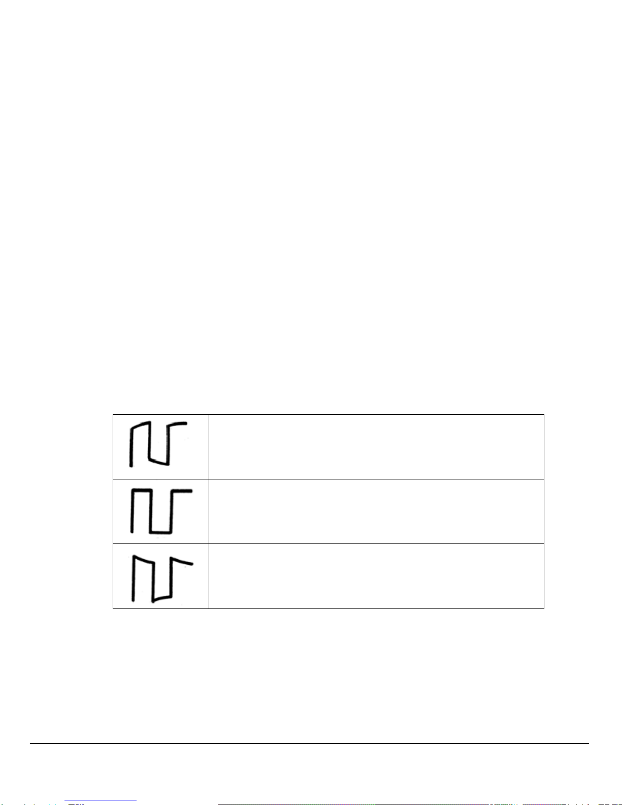
2. Check the displayed waveforms and compare them with the
following figure.
Under Compensated
Compensated Correctly
Over Compensated
3. Use a nonmetallic driver to adjust the low-frequency compensation
adjustment hole on the probe until the waveform changes to be
correct as the figure above.

11
Function Introduction of Front Panel

12
○
1Power On/Off.
○
2Menus On/Off.
○
3Universal Knob.
Adjust waveform brightness While the light above the knob is
dark, adjusting the knob will change the waveform brightness,
which ranges from 30%~100%. Turning clockwise means increase
while counterclockwise means decrease. You can also select
“intensity” in “DISPLAY” menu and then adjust the knob to change
the waveform brightness.
Universal knob When the light above the knob is lighted, you could
select anyone submenu by adjusting the knob under the current
menu. In addition, it can also be used to modify parameters and
input filename.
○
4Function Menus.
: Press the button to enter the cursor measurement
function menu. The instrument provides three measure modes:
Manual, Track and Auto.

13
: Press the button to enter the acquire function menu,
under which you could set the acquisition mode, sampling mode
and dot inserting mode.
: Press the button to enter the file save and recall function
menu. There are four types of file to be saved which are
respectively setups, waveforms, picture and CSV, and additionally
the factory setup are supported.
: Press the button to enter the measurement function menu.
There are three measure types: voltage, time and delay. Each kind
of them contains many measurement parameters, you could press
any of them to display the corresponding value.
: Press the button to enter the display function menu,
under which you could set waveform display type, persist time,
waveform brightness, display format, menu display and so on.
: Press the button to enter the utility function menu, under
which you could set the corresponding function of the system, some
parameters like Sound, Language, Interface and so on. In addition,
some advanced functions are also supported such as Self
Calibration, Firmware Update, Pass/Fail test.
○
5Default Setup.
: Press the button to restore the oscilloscope to its default
settings. The default voltage scale and time base are respectively
1v/div and 500us.
○
6Help.
: Press the button to enable HELP function, and then press
down any menu to display corresponding help information. To
display the submenus help information of the current menu, firstly
you should open the current menu, and then press down the
“HELP” button, the last step is to select any submenu you want.
14
○
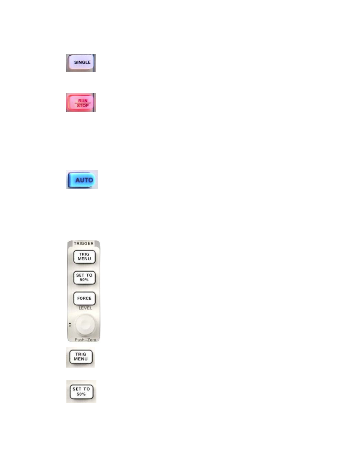
7Single:
: Press the button to turn the trigger mode to “Single”.
○
8Run/Stop:
: Press the button to set the state of the instrument to
“RUN” or “STOP”.
When in “RUN”, the indicator light displays yellow;
When in “STOP”, it displays red.
○
9AUTO.
: Press the button to enable the waveform auto setting
function. The oscilloscope will automatically adjust the horizontal
time base, vertical scale and trigger mode according to the input
signal to make the waveform displays in a perfect state.
○
10 Trigger Control Area:
: Press the button to open trigger menu under which five
trigger modes are supported.
: Press the button to set trigger level to the middle of the
maximal voltage and the minimal voltage to quickly stabilize the
current waveform.

15
: Press the button to make the signal trigger forcefully.
: Modify the trigger level. Turn it clockwise or
counterclockwise to increase or decrease the level. The trigger
level will move up or down and the value in the message box at the
lower-left corner of the screen will change as the trigger level
changes. Press it down to reset the trigger level to the screen
vertical center.
○
11 Probe Compensation.
○
12 Horizontal Control Area:
: Press the button to open horizontal control menu under
which you can turn on/off the delay sweep function and switch the
save modes between “long save” and “normal save”.
: Modify the trigger position. The trigger point will move left
or right relative to the center of the screen when you adjust the knob.
The waveform will move left or right and the trigger position
message at the lower-left corner of the screen will also change as
the position changes. Press the knob to quickly reset the trigger
position to zero.
: Modify the horizontal time base. Turn it clockwise or
counterclockwise to decrease or increase the time base. The
waveform will display expanded or compressed and the time base
message at the nether side of the screen will change as the time
base changes. Press down the knob to quickly switch to the delay

16
sweep state.
○
13 EXT TRIG Terminal.
○
14 Vertical Control Area:
: Input channels. These two channels are
marked with different colors to distinguish different input channels
and their waveforms. Pressing the channel button will turn on the
corresponding channel as well as its menu, and pressing it twice
continuously will turn off the channel.
: Press the button to enable math function which includes
five operations: adding, subtracting, multiplying, dividing and FFT.
: Press the button to enable the reference waveform
function. By recalling the previously saved waveform, we could
compare it with the current waveform to decide circuit failures.
: Modify vertical position of the current waveform. Turn
clockwise to increase the position while turn counterclockwise to
decrease it. The waveform will move up or down and the position
message at the lower-left corner of the screen will change along.
Press down the knob to quickly reset the vertical position to zero.
:Modify vertical scale of the current channel. Turn
clockwise to decrease the voltage scale while turn
counterclockwise to increase it. The amplitude of the waveform will

17
enlarge or reduce and the scale message at the lower-left corner of
the screen will also change as the scale changes. Press down the
knob to quickly switch the vertical scale adjustment modes between
“Coarse” and “Fine”.
○
15 Channel Input Terminal.
○
16 Menu Select keys.
○
17 Print Key:
: Press the button to enable the reference waveform
function. By recalling the previously saved waveform, we could
compare it with the current waveform to decide circuit failures.
○
18 USB Host Interface.
Rear Panel Description
○
1Handle:
Pull up the handle vertically for easy carrying. Press it down if you
do not need the handle.
○
2AC Power Input Terminal:
○
1
○
6○
5○
4○
3
○
2

18
The power available of the oscilloscope is 100~240V, 45~440Hz.
Please use the power cord provided as accessories to connect the
instrument to AC power.
○
3USB Device Interface:
Pick Bridge printer or PC can be connected via this interface to print
the current interface of the oscilloscope or control the instrument
through PC software.
○
4RS-232 Interface:
The terminal can be used to connect the oscilloscope with a PC to
update software, control remotely via special software.
○
5Pass/Fail Output Terminal:
The pass/Fail testing pulse are put out via this terminal.
○
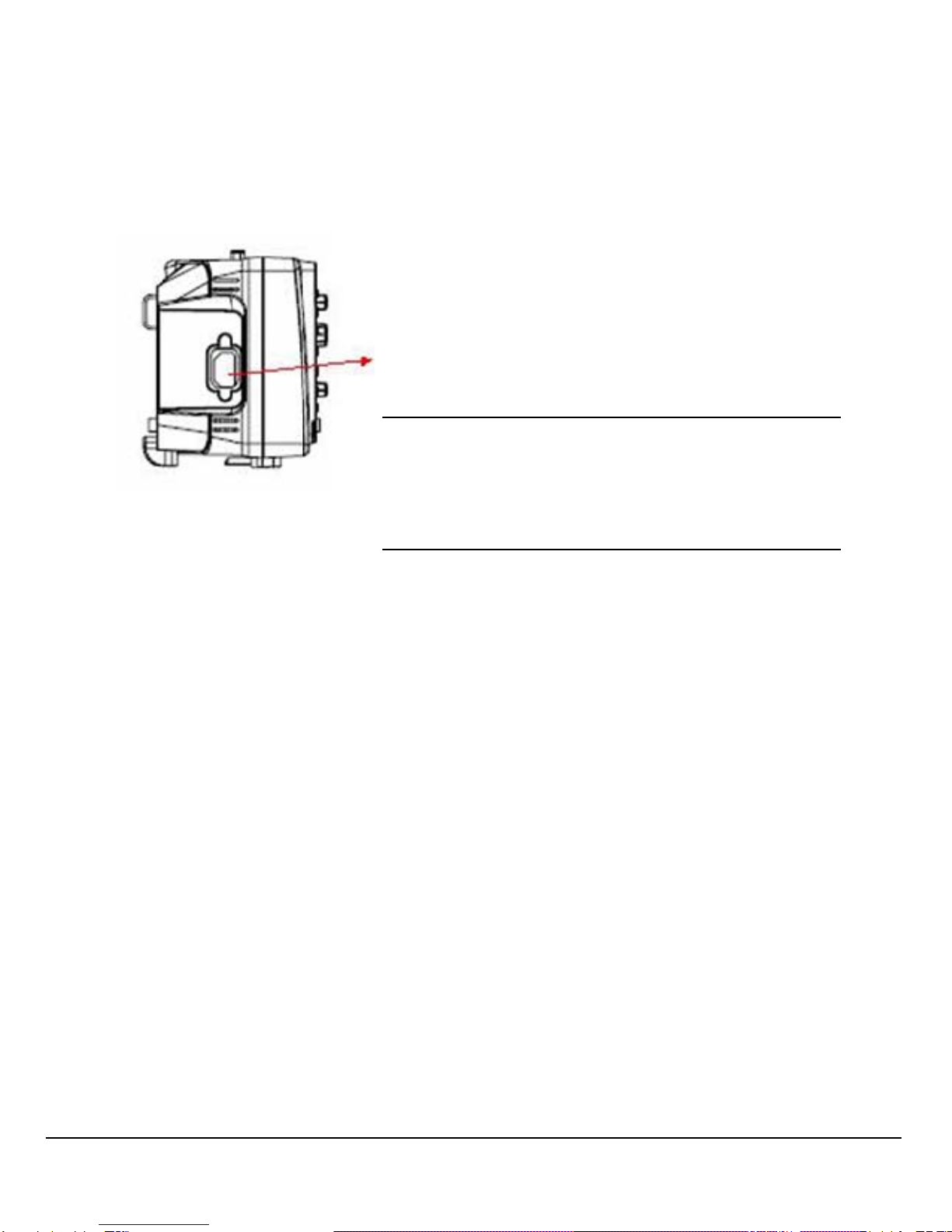
6Lock hole:
You could lock the instrument in a fixed location using a security
lock (please buy it yourself) via the lock hole.

19
Rear Panel Description
○
1Working state:
Available working states include Ready, Auto, Trig’d, Scan and
Stop.
○
2Waveform memory:
Display the position of the current waveform in the memory of the
oscilloscope.
○
3Trigger position:
Display the trigger position of the waveform in the memory and on
the screen.
○
4Print:
Display the current state of “Print Key” under the menu of “Print
Setup”.
P: “Print Key” option set to “Print Picture”;
○
1
○
6
○
5
○
4
○
3
○
2
○
7
○
8
○
9
○
10
○
11○
12
○
13
○
14

20
S: “Print Key” option set to “Save Picture”.
○
5Back USB Device:
“Back USB” supports two types of interface: USBTMC and Printer.
○
6Trigger Setting:
Trigger Level. Display the position of the current trigger level, for
example: ;.
Trigger Type. Display the current trigger type and trigger condition.
Different trigger types have different marks, for example: means
triggered on Slop side in edge trigger.
○
7Frequency Counter:
Display the firmware frequency of current waveform. To display it,
you should turn on the “Counter” in menu of “UTILITY”.
○
8Trigger Position:
Use HORIZONTAL POSITION Knob to modify the parameter. Turn
clockwise or counterclockwise to make the red arrowhead move
right or left, which will respectively cause the decrease and
increase of the parameter in the message box at the lower-left
corner of the screen. Press down the knob to automatically reset
the parameter to zero as well as make the red arrowhead return to
its initial position.
○
9Horizontal Time Base:
Represent the time of each grid on the horizontal axis of the screen.
You could revolve HORIZONTAL SCALE Knob to modify the
parameter which is variable from 2.5nS to 50S.
○
10 BW Limit:
If the current “BW Limit” is “On”, then the mark B displays at the
lower-corner of the screen, or nothing displays. When the vertical
scale is 2mV/div, the “BW Limit” turns on automatically.
Table of contents
Other Pintek Test Equipment manuals


Popular Test Equipment manuals by other brands


Martel
Martel MC1000 manual

CPI
CPI Millenia Series Operator's manual

Fluke Calibration
Fluke Calibration 5560A Programmer's manual

Krohn-Hite
Krohn-Hite 526 operating manual

Keysight Technologies
Keysight Technologies U3022AM06 User's and service guide

Precision Rated Optics
Precision Rated Optics TP-P6 manual