Temperature
characteristics 0.05 x accuracy specifications/ ( ) at 0 to 40 (32 to 104 )
Storage temperature
range -10 to 50 (14 to 122 ) (no condensation)
Power source Rated power voltage 9 VDC
6F22 layer-built manganese battery x 1
Maximum rated power100 mVA
Battery lifetime Approx. 45 hours (continuous, no load)
External dimensions
and mass Approx. 62W x 216.5H x 39D mm, Approx. 350 g (3281)
Approx. 2.44"W x 8.58"H x 1.54"D, Approx. 12.3 oz. (3281)
Approx. 62W x 231H x 39D mm, Approx. 400 g (3282)
Approx. 2.44"W x 9.06"H x 1.54"D, Approx. 14.1 oz. (3282)
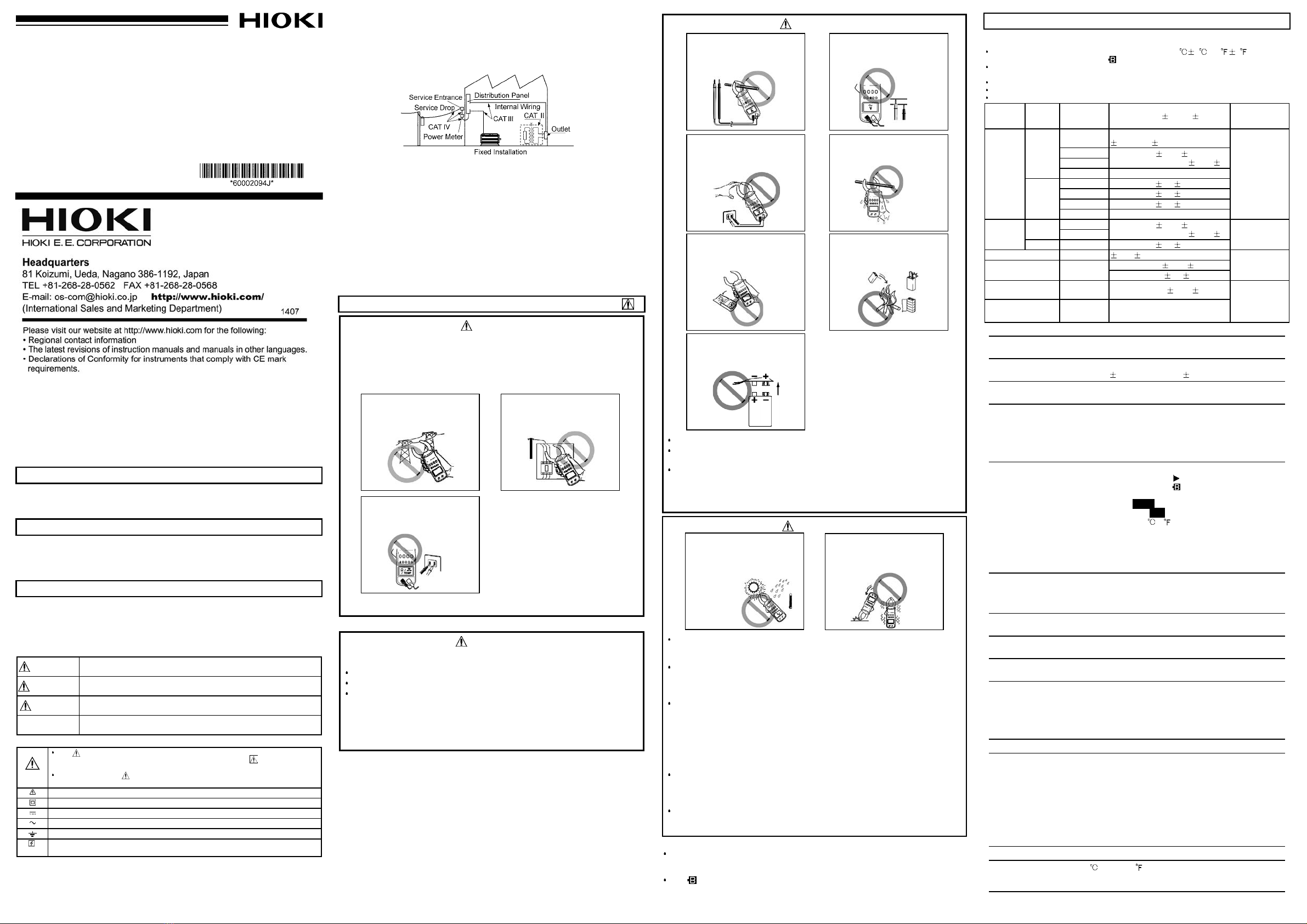
Names and Functions of Parts
Voltagae and resistance
input terminal
3281
(
600 A
)
3282
(
1000 A
)
Clamp-on
sensor
Lever
Key switchs
Display (LCD)
Back casing
(back)
Alternating current
AUTO
SLO
REC
MAX
MIN
AVE
Auto-ranging
Display update:
approx. once per three seconds
Record function
Maximum value
Minimum value
Average value = (maximum value
+ minimum value) / 2
min
hour
HOLD
APS
*
*
Ω,kΩ
One minute: one segment (bar
graph)
One hour: one segment (bar
graph)
Data hold
Auto power-off
Centigrade
Fahrenheit
Resistance
Continuity
Hz
V
A
RMS
PEAK
C.F.
Frequency
Voltage
Current
True RMS value
Peak value
Crest factor = Peak value /
Effective value
Input over (bar graph)
Battery consumption warning
Measurement Procedure
Preparation
Battery depleted.
"" lights.
The buzzer beeps three times to warn
that the battery must be replaced.
Measurements taken at this battery level
is not guaranteed for accuracy.
AC current (ACA) measurement A
OK
NG NG
Wave
form Peak
ave Peak
Triangular
wave Peak
C.F. 1.41 1.73 1
Hz RMS
AC voltage measurement V
Black Red
Plug in the test leads
Resistance measurement
Black Red
Continuity check
Data hold function HOLD
Auto power-off function APS
Battery consumption warning
Buzzer
FAST mode
Record function REC
MAX MIN AVE Instantaneous value
Battery Replacement Procedure
WARNING
When replacing the battery, be sure to insert them with the correct
polarity.
Otherwise, poor performance or damage from battery leakage could result.
Replace battery only with the specified type.
CAUTION
Do not fix the back casing screws too tightly.T
he torque about 0.5N
・
m is recommended.
How to Attach the Hand Strap
Troubleshooting
Symptom Battery Battery snap Test leads
The instrument cannot be
powered on. -
Power is cut off immediately
after it is turned on.*- -
"" lights. - -
The instrument is powered
off during operation.*-
Voltage measurement does
not function. - -
Resistance measurement
does not function. - -
Remedy:
If the trouble cannot be
remedied, send the
instrument for repair.
Replace with a
new battery. The terminals of
the battery snap
are poorly
contact.
Check the test
leads wiring.
An indication E.001 to E.005 appears. Send the instrument for repair.
Service
3. Accessories
Model L9207-10 Test Lead (black and red set), Instruction manual,Model 9399 Carrying
Case, Hand strap, 6F22 (006P) battery
*: The temperature measurement function is only available for customers
who have the THERMISTOR TEMPERATURE PROBE 9462.
Model 9462 will be discontinued effective May 18, 2011
1. Loosen the case back screw, and load the battery in the unit. (Refer to Battery
Replacement Procedure on page 11.)
2. Press the POWER key to power on the unit. Check to make sure that all display
segments light.
3. The instrument is in the AC current measurement state.
Low battery voltage detection function
After the mark lights and battery voltage drops below a certain level, the power goes
off automatically. When this occurs, bAtt and Lo are displayed.
When power goes off after display of these marks, replace the exhausted battery with a
new one.
1. Press the key.
2. Position the conductor within the clamp
sensor centered.
Make sure that only one conductor is in
the clamp sensor.
The effective value (RMS) of current is
displayed in the digital and bar graph.
Ranging is automatic (AUTO).
NOTE
Use data hold function when you abolish indication and want to read it.
Please note that waveforms that include elements outside the frequency characteristic
range may not be measured correctly.
Current measurements exceeding 600 A AC should be of short duration. Heat builds
up in the clamp sensor proportionate to the current value, and will reach a dangerous
level over a long period of time.
Range selection
Pressing the RANGE key repeatedly cycles through the 30 A, 300 A, 600 A and AUTO
ranges.
Changing the display update SLOW
When the readings fluctuate and are difficult to take, it is possible to make the display
update slow (approx. once per three seconds), and the readings easy to take. The
screen-updating speed cannot be changed for the bar-graph display.
Pressing the SLOW/PEAK key repeatedly changes the display as follows.
Peak value display PEAK
The peak value is displayed. The effective value is displayed in the bar graph.
NOTE
Mode displaying the PEAK (peak value) of a continuous wave which lasts for more
than 250 ms.
To keep the displayed value, use the recording function in the PEAK display mode
(refer to recording function REC 1.).
As there is a period whereby no sampling is done on this instrument, it may not be
possible to measure an instantaneous peak current that does not reach 250 ms, such
as the motor starting current, even when the recording function is used.
To accurately measure an instantaneous peak current such as an inrush current,
please use HIOKI
’
s 3284, 3285, and 3285-20.
Crest factor display C.F.
The crest factor of a waveform is displayed.
Crest factor = Peak value / Effective value
The crest factor of a sine waveform where
no distorted, and the harmonic components
are included.
When the crest factor of current is being
displayed, "A" flashes. The effective value is
displayed in the bar graph.
Frequency display Hz
1. Press the Hz key.
2. Pressing the Hz key changes the display.
3. The frequency of the current being measured is displayed.
When no input is applied, "----" is displayed. When measuring the current frequency,
"A" flashes. The effective value is displayed in the bar graph.
NOTE
When the frequency is lower than 30 Hz, "----" is displayed.
The AUTO range display indicates the current range.
1. Press the key.
2. The effective value (RMS) of voltage is displayed in
the digital display and bar graph.
The display update changing, and the peak value,
crest factor and frequency displays are possible as
well as in the AC current measurement.
NOTE
Be sure to use the test leads with the sleeves
attached when performing measurements in the CAT
III and CAT IV measurement categories. In the
CATII environment, if the tips of the test leads do not
reach the measurement object, remove the rigid insulating sleeve before measuring.
Please note that waveforms that include elements outside the frequency characteristic
range may not be measured correctly.
1. Insert test lead in the instrument as the figure.
2. Attach or remove the rigid insulating sleeve as
required by the measurement object.
3. Pressing the Ω//TEMP key repeatedly, and let me
indicate Ω. Changes the display as follows.
Ω
(Centigrade) (Fahrenheit)
*:The temperature measurement function is only
available for customers who have the THERMISTOR TEMPERATURE PROBE 9462.
Model 9462 will be discontinued effective May 18, 2011
4.The resistance value is displayed in the digital display and bar graph. Ranging is
automatic (AUTO).
NOTE
If a voltage is input, a warning beep will sound. Stop measurement immediately. (The
internal circuit is protected against up to AC 600 V.)
In some cases, the alarm does not beep for DC or DC weighted components.
1. Let me indicate " " in the same way as the resistance measurement.
2. The buzzer beeps at less than approximately 30 Ω, and " " flashes.
NOTE
The digital display indicates the measured resistance value.
If a voltage is input, a warning beep will sound. Stop measurement immediately. (The
internal circuit is protected against up to AC 600 V.)
In some cases, the alarm does not beep for DC or DC weighted components.
Data hold functions to "stop" the display at its present reading.
1. Press the HOLD key. "HOLD" appears, and the digital and bar graph displays are
held.
This function is effective for all measurement functions and modes.
To release this function, press the HOLD key again.
When "APS" is being displayed, the auto power-off function is effective.
The unit is powered off in approx. 10 minutes unless any key is pressed.
"APS" flashes and the alarm beeps for approx. 30 seconds just before the unit is
powered off.
Pressing a key other than the POWER key prolongs the auto power-off function for 10
minutes.
To release the auto power-off function, press the POWER key while holding down the
HOLD key to power on the unit. In this case, "APS" does not appear.
When using the record function, the auto power-off function is ineffective.
If is indicated, the battery power is running low and accuracy cannot be guaranteed.
Replace with a new battery. Refer to "Preparation" for the confirmation of the capacity of
the battery.
To turn off the buzzer, press the POWER key while holding down the RANGE key to
power on the instrument. The alarm and continuity buzzers cannot be turned off.
Make it FAST mode when you measure load currents with variations.
The digital display update can be set to approx. 4 times per second.
1. Press the key twice to set to the FAST mode.
"F" appears for an instance, and the unit enters the FAST mode.
Then "F" appears each time the or key is pressed.
2. Press the RANGE key to fix the current range.
3. It is convenient for taking readings to hold the maximum value (MAX) by using the
record function.
4. To release the FAST mode, press the key twice again.
NOTE
The stable measurement cannot be made unless the waveform lasts for more than
250 ms.
Push a key in the case of the voltage measurement as well after it is made FAST
mode.
This mode is not effective for the resistance, continuity and temperature
measurements.
If setting to the SLOW display in the FAST mode, the display update is the same as
in the normal mode (approx. twice per second).
Use the recording function to hold the maximum and minimum measured values and
maximum/minimum averages.
1. Measurement indicated value
Pressing the MAX/MIN key during measurements of current, voltage, or frequency
activates the recording function. REC flashes and the instrument saves the
maximum value (MAX), minimum value (MIN), and average value (AVE) in internal
memory from the instant you press the MAX/MIN key. Pressing the MAX/MIN key
with the recording function activated switches the display as shown below. If MAX,
MIN, or AVE is not displayed, an instantaneous value is assumed.
Data (MAX, MIN, AVE) remains displayed while the display is switched. If maximum
or minimum data is updated in the meantime, however, the data values will change.
With the recording function activated, the auto power-off function remains disabled.
(APS off.)
The average value (AVE) displayed is calculated by: Average Value = [(Maximum
value + Minimum Value)/2].
After pressing the SLOW/PEAK key to display the peak value, activate the recording
function and select MAX. The peak hold function will be activated.
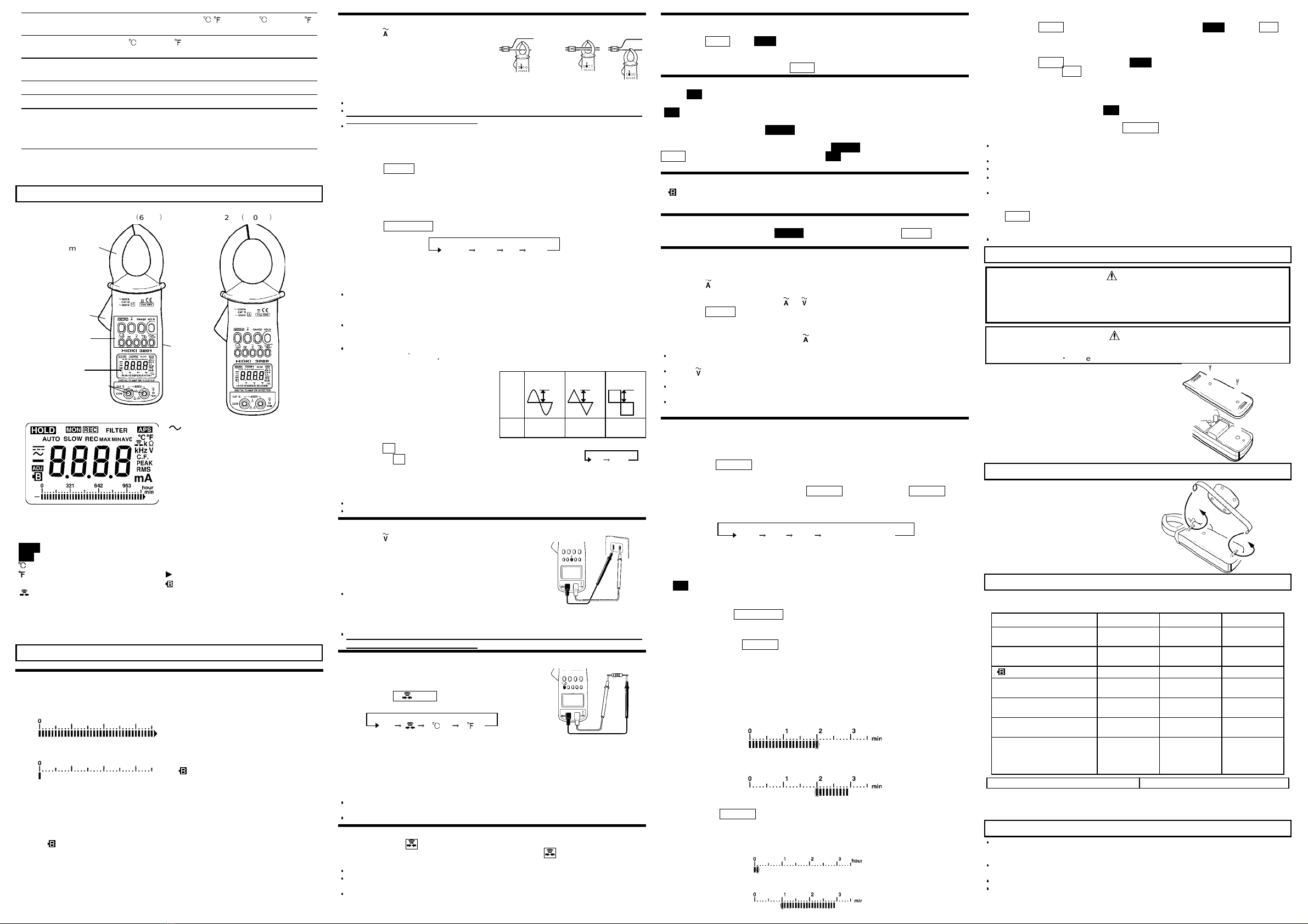
2. Display of Elapsed Time
When you press the MAX/MIN key to activate the recording function, the bar graph
segments flash and the elapsed time appears.
When "min" is shown in the right-hand corner of the bar graph, each segment of the
bar graph corresponds to one minute. Every time one minute elapses, one segment
of the flashing bar graph goes on. When all segments on the bar graph go on, the
elapsed time is 30 minutes.
When the elapsed time exceeds 30 minutes, one segment of the flashing bar graph
goes off every time one minute elapses.
When the segments left of a flashing segment remain on: the number of "on"
segments represents the elapsed time (0 to 29).
The illustration below shows when 20 minutes have elapsed:
When the segments right of a flashing segment remain on: the number of "off"
segments (+30) represents the elapsed time (30 to 59).
The illustration below shows when 50 minutes have elapsed:
When digital display switches the average value (AVE) to a instantaneous value when
you press the MAX/MIN key, the right corner of the bar graph indicates hours. In this
mode, each segment of the bar graph corresponds to one hour. The way to read the
bar graph here is similar to reading it in minutes. When all bar graph segments
remain on, the elapsed time is 29 hours.
The illustration below shows when one hour, 40 minutes have elapsed.
3. Deactivation of Recording Function
Pressing the HOLD key deactivates the recording function. HOLD goes on, REC
stops flashing and goes on, and the elapsed time stops incrementing. While the
recording function is being deactivated, data is not updated, even if the clamp sensor
is disconnected from the conductor.
Pressing the HOLD key again cancels HOLD display and activates the recording
function again, with REC flashing again.
4. Cancellation and Resetting of Recording Function
To cancel the recording function, press the related function key (A, V or Hz) for the
measurement in progress. Once the recording function is canceled, the auto power-
off function becomes effective. (APS goes on.)
To restart the unit after resetting the data, temporarily cancel the recording function,
then activate it again by pressing the MAX/MIN key.
Note
An instantaneous power failure and a surge cannot be detected. The record function
is not effective for the resistance and temperature measurements.
The maximum recording duration depends on the remaining battery capacity.
The lowest possible frequency that can be displayed is 30 Hz.
If changing the range when "O.L." is being displayed in any of the displays, the held
data and elapsed time are cleared.
When you need minimum value and average value data, make sure to activate the
recording function during measurement. If the function is activated when there is no
input, the minimum value will remain zero. To deactivate the recording function, press
the HOLD key to terminate measurement. If you disconnect the clamp sensor or test
lead from the circuit under measurement without deactivating the recording function
beforehand, the minimum value will be zero.
When the unit is turned off, accumulated data are lost.
1. Remove the two back casing screws, and take
off the back casing.
2. Remove the old battery without pulling the
codes of the snap.
3. Install a new battery in the battery snap
securely.
4. Attach the back casing.
The hand strap improves the operation.
Although the instrument seems to be out of order in the following cases, there may be
the causes of the troubles. Check it again before you send it for repair.
*:When the battery is drained, the relay may be operated immediately after the power
is turned on or when the measurement function is changed, and the power may
suddenly be cut off. Replace the battery with a new one when this arises.
To clean the instrument, wipe it gently with a soft cloth moistened with water or mild
detergent. Never use solvents such as benzene, alcohol, acetone, ether, ketones,
thinners or gasoline, as they can deform and discolor the case.
The shortest period for possession of the repair parts is 5 years after stopping the
production.
For inquiries about service, contact your dealer or Hioki representative.
Pack the instrument carefully so that it will not be damaged during shipment, and
include a detailed written description of the problem. Hioki cannot be responsible for
damage that occurs during shipment.