SERVICE CHECK SHEET
MODE CHECK CONTENTS CHECK TARGET OPERATION POINT, SETTING INDICATION POINT STATE CHECK
TEST
MODE
VERSION Firmware LCD
Caution : If PAD calibration has not been carried out, PAD unexecuted will blink
red.
System :
Main Application :
Main Kernel :
Led Micon :
Key Micon :
LED ALL ON, LCD WHITE All LEDs are ON,
LCD display
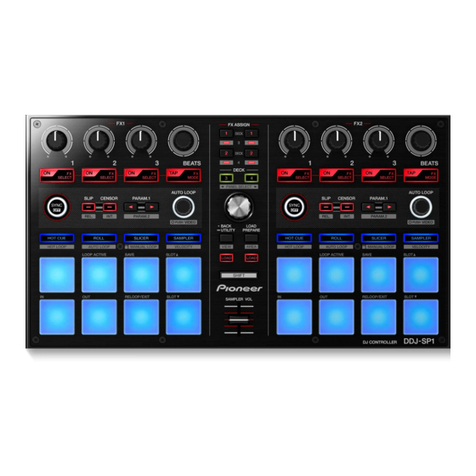
[MUTE]
Multicolor LED
(Performance pad, 16
step key)
Lights white when pressed
[HOT SLICE] Lights red when pressed
[SLICE] Lights green when pressed
[SCALE] Lights blue when pressed
LED ALL OFF,
LCD BLACK
All LEDs are OFF,
LCD display
All LED, LCD LED OFF, LCD black screen
BUTTONS, PADSAll buttons, pads LED button (self lighting button) × 36 LCD [ON, OFF] indication of pressed state, [OK] indication by pressing all buttons
Button (without LED) × 5 [ON, OFF] indication of pressed state, [OK] indication by pressing all buttons
Performance pad × 16 [ON, OFF] indication of pressed state, [OK] indication by pressing all buttons
[NUDGE] button × 2 [ON, OFF] indication of pressed state, [OK] indication by pressing all buttons
VOLUMES, RIBBON,
TEMPO SLIDER
Volumes, Ribbon, Tempo
slider
Headphone LEVEL knob LCD Numerical value display changes according to the position of knob, and when
upper limit value and lower limit value are reached [OK] display
FX LEVEL DEPTH knob Numerical value display changes according to the position of knob, and when
upper limit value and lower limit value are reached [OK] display
Touch strip Numerical value display changes according to the operation position, and
when upper limit value and lower limit value are reached [OK] display
TEMPO slider Numerical value display changes according to the slider position, and when
upper limit value and lower limit value are reached [OK] display
ENCORDERSEncorders Rotary selector LCD [OK] indication in clockwise +5 or more / counterclockwise direction -5 or less
Indentation state is displayed as [ON, OFF]
Parameter adjustment knob Encoder 1 [OK] indication in clockwise +5 or more / counterclockwise direction -5 or less
Encoder 2 [OK] indication in clockwise +5 or more / counterclockwise direction -5 or less
Encoder 3[OK] indication in clockwise +5 or more / counterclockwise direction -5 or less
Encoder 4 [OK] indication in clockwise +5 or more / counterclockwise direction -5 or less
Encoder 5 [OK] indication in clockwise +5 or more / counterclockwise direction -5 or less
Encoder 6 [OK] indication in clockwise +5 or more / counterclockwise direction -5 or less
TOUCH PANEL Touch panel accuracy Touch panel Rectangle displayed at
the four corners of
LCD
Change to blue when Touch, All square touch [OK]
Calibration Touch panel Press [REC] to enter mode LCD (upper left -> upper
right -> lower left ->
lower right)
Touch the + center of displayed red square and press [REC] button Only check [NG] performed
ETHER DEVICE MAC/IP address LCD MAC ADDRESS : : : : :
MAC ADDRESS(USB) : : : : :
IP ADDRESS . . .
* Connect to the PC with LAN and confirm communication with Ping
command
DIN MIDI MIDI terminal Connect DIN-MIDI OUT and
IN with MIDI cable
LCD Touch [TEST] button to display the check result
PRESET SAMPLE COPY Built-in eMMC memory Touch panel Connect USB memory with
sound source
LCD Touch [START COPY] button to transfer * When replacing MAIN
ASSY
AUDIO ROUTE Audio circuit Touch panel INPUT device,
connection
OUTPUT 1 Touch [Mode 1] button and INPUT signal is output
THRU/OUTPUT 2 Each time touch [Limiter] button, limiter turns ON / OFF ( limiter is
adjusted with INPUT LEVEL)
PHONES
THRU/OUTPUT 2 Touch [Mode 2] button and INPUT signal is output
Each time touch [Limiter] button, limiter turns ON / OFF
(limiter is adjusted with INPUT LEVEL)


