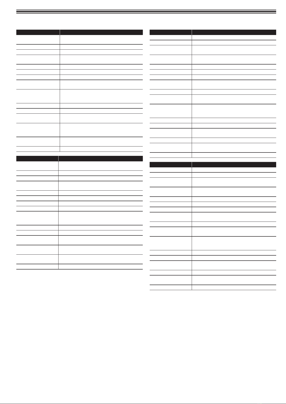
PIONEER DJ XPRS2 Series User manual

How to read this manual
Thank you for choosing this speaker. To make sure you get the most from
its functions and use them effectively, please read the Instruction manual
and Precautions for Use carefully.
Please keep the Instruction manual and Precautions for Use together
with the Warranty.
Main features
2000-W high output and high sound quality are achieved by mounting
a D-class amplier module in a wooden cabinet featuring outstanding
acoustic characteristics. The XPRS2 can be used not only as a stationary
sound system in a stationary facility but also as sound equipment for
events as it can be easily transported and set up quickly.
• System type: Multi-purpose, active loudspeaker with DSP controls
• Transducer driver: 1-inch exit compression driver, 1.75-inch voice coil
• Subwoofer: ferrite woofer, 3-inch (76 mm) voice coil with long excursion
• Power rating: Class D 2000 W (peak)
• 4 DSP modes: LIVE/MUSIC/SPEECH/MONITOR
• Subwoofer: 80 Hz, 100 Hz, 120 Hz (NORMAL, BOOST, EXTENDED
LF)
• Electronic protections: Thermal/overload/digital limiter/compressor
• Power supply: 110 V – 240 V (50 Hz / 60 Hz)
• Enclosure construction: Plywood cabinet, black paint, rubber feet,
metal handle
• Mounting: One metal standard pole-mount, 10 x M10 threaded inserts
plus integrated pull-back cover
Rear panel
(full-range models)
INPUT
MIC/LINE
STEREO
HI-ZPOWER
HI-Z/LINE
SIGSIG
MIC
SIGSIG/LIMITER
OFF MAXOFF MAXOFF MAX
DIGITAL SIGNAL P ROCESSING
DSP
DISPLAY
MASTER
VO L
123
MIX OU T
2
e
5
d
c
b
a
9
8
3
4
1
6
7
1 AC INPUT
Connect the power cord to AC IN and then to the power outlet.
2 POWER
AC switch for turning the power on or off. When POWER is turned ON,
the POWER LED and the LCD screen both light up.
3 INPUT1
Level control for the LINE/MIC INPUT 1.
INPUT
Balanced input for sources such as mixing consoles, instruments, or
microphones. Connections can be made via a 1/4-inch TRS or XLR
connector.
4 INPUT2
Level control for the Hl-Z/LINE INPUT 2.
INPUT
Balanced input for sources such as mixing consoles, instruments, or
microphones. Connections can be made using a 1/4-inch TRS or XLR
connector.
5 STEREO LEVEL
Line input level control for STEREO.
6 INPUT LEVEL
Level control of the individual input.
7 Hl-Z signal light
When sound from a guitar is input, the system setting changes to Hl-Z
sensitivity and the signal light turns on.
8 MIC signal light
When sound from a microphone is input, the light turns on when the
system setting changes to MIC sensitivity.
9 SIG single channel signal light
When there is a signal, the signal light turns on.
aLCD
DSP control and monitoring interface.
bMASTER VOL
Total volume adjustment range: -60 dB – +10 dB.
DSP
Scroll through the menus and choose from the options. Press the
MASTER VOL knob to select an item on a menu.
cSIG/LIMITER signal light
Lights up green when there is a signal, and red when the amplifier
starts to compress.
dPOWER indicators
Llights up when the speaker is turned on.
eMIX OUT
The XLR output sends mixed input signals to other speakers or
subwoofers. INPUT LEVEL controls the level of the signal sent to the
MIX OUT. The MASTER VOL or DSP control settings do not affect the
mixed output.

Rear panel
(subwoofer model)
12
3
4
5
a
8
9
6
7
1 AC INPUT
The AC connection is established via the IEC connector. The IEC
connector is compatible with a lockout power cord (not included).
2 POWER
AC switch for turning the power on or off. When POWER is turned on,
the LED lights up.
3 LINK
The XLR output sends mixed input signals to other speakers or
subwoofers. VOLUME (input level) controls the level of signal sent to
LINK. The MASTER VOL and DSP control settings do not affect the
LINK signal.
4 INPUT LEFT (mono)/RIGHT
5 POWER indicators
The POWER LED lights up when the speaker is turned on.
6 SIG/LIMITER signal light
Lights up green when there is a signal, and red when the amplifier
starts to compress.
7 3DSP PRESET MODES
BOOST/EXTENDED LF/NORMAL
8 LPF
80 Hz/100 Hz/120 Hz
9 POLARITY
REVERSE/NORMAL
aVOLUME
Level control of an input signal.
DSP control
With the integrated DSP control menu, you can choose from multiple
DSP and system settings on the speaker.
To access the DSP control menu, follow the steps below.
1. Press the MASTER VOL knob and the DSP control menu will
appear.
2. Use the MASTER VOL knob to scroll through the menu items.
3. Press the MASTER VOL knob to select the menu item you want to
modify.
The menu item you chose will open on the right side of the DSP menu.
4. Use the MASTER VOL knob to scroll through the menu items.
5. Press the MASTER VOL knob to select a setting.
The setting will be saved and you will return to the level above in the
menu.
XPRS122
6. Repeat steps 2 through 5 to modify other DSP and system settings.
7. Select EXIT to return to the main screen.
Full-range speaker DSP control menu
Full-range speaker DSP control menus are included on the XPRS102
and XPRS122 units.
EXIT menu item
Use the EXIT menu item to return to the home screen.
NOTE
After a minute of menu inactivity, the display turns off but the speaker
continues working as normal.

MENU
You can use the Input Settings menu to congure the speaker’s input
sensitivity control as well as the Delay and Phase control settings.
The MIC setting is for the Input 1 input sensitivity control. After selecting
the MIC input, the MIC light on the panel will turn on.
The Hl-Z setting is for the input 2 input sensitivity control. After selecting
the Hl-Z input, the Hl-Z light on the panel will turn on.
The Delay menu is for creating time calibrations with other speakers.
The options available range between 0 and 69.19 feet. The delay can be
changed in increments of 0.69 feet. The default setting is 0 feet.
Phase setting preset for the entire loudspeaker system.
The Factory Presets menu is for conguring the type of sound the
speaker sends. The options are: LIVE, MUSIC, SPEECH, and MONITOR.
You can use the MASTER VOL menu button to congure the presets for
different situations.
• LIVE – for live sound applications (default).
• MUSIC – for recording music and playing dance music.
• SPEECH – for voice-only applications.
• MONITOR – for ground monitoring.
The Sub Setting menu is for selecting the high-pass frequency or
matching subwoofer when one is used in the speaker setup. The options
available for this selection are: No Sub, 80 Hz (80 Hz), 100 Hz (100 Hz),
120 Hz (120 Hz), 150 Hz (150 Hz), and the Qualcomm is a 24 dB/octave
Linkwitz/Riley crossover. The 80 Hz (100 Hz), 100 Hz (100 Hz), 120 Hz
(120 Hz), and 150 Hz (150 Hz) options are general high-pass settings
for use with other subwoofers. The settings are optimized for the woofer
(including delays for optimal overlay).
The default is No Sub.
EQ menu
The EQ menu is a 4-band EQ (equalizer) that you can ne tune in
addition to FUNCTION and LOCATION. The options available are: HI,
MD, LM, and LO.
Back
HI 12.1K Default: 0 decibels
MD 2.52K Range: -18 decibels – +18 decibels
LM 500.0 ALLBYPASS will be deleted, invalidating all set EQs.
LO 101.5 FLAT is to restore all adjusted EQs to factory settings.
NOTE
The indoor equalizer (EQ) range shown is the factory default range for
individual speakers. When the woofer is selected, any EQ below the
crossover point is bypassed.
To use EQ above the crossover point, do the following.
> Rotate the MASTER VOL knob to reach the desired frequency.
User Programs (saved user settings)
There are 16 presets that you can change and save EQ values for. You
can also give them custom names with 7 English letters/symbols. Use
the load/save/delete options to do this.
System menu
The System menu is for conguring the system. You can also congure
the accessibility of this menu and modify the settings, and reset to factory
defaults.
The FIRMWARE/HARDWARE menu displays the current preset and
rmware version.
XPRS122
The Name menu shows the name of the current speaker. This menu
enables you to customize the name of the speaker.
The Default Settings menu is for resetting the speakers to their original
factory settings. The options for this selection are: NO or YES.
The Exit menu is for returning to the main menu.
To reset your system to the original factory settings, follow the steps
below.
1. From the System menu in the DSP menu, select Default Settings.
XPRS122
A message prompt to restore the factory settings will appear.

2. Select Yes.
3. When the prompt asks if you’re sure, select Yes.
The speaker will reboot the system and reset to the original factory
settings.
Installation and connections
Important notes on installation
The sound produced by the speaker is subtly inuenced by the conditions
of the room you use it in. Carefully consider the installation location
before setting up the speaker to ensure the best possible conditions.
AlphaTheta Corporation will not be liable for any damages arising
from use of the speaker (including but not limited to loss of business
opportunities), regardless of the installation method used.
Be sure to use the handles on the top or the sides of the speaker when
moving and installing it.
CAUTION
• To help proper cooling, please make sure enough space is kept
between each speaker and nearby walls or other components
(minimum 30 cm or more above, behind, and to the sides of each
speaker). Leaving insufficient space may cause the temperature inside
the speaker to rise, leading to malfunction or permanent damage.
• Use of this product while it is stacked is prohibited.
Installation using a speaker pole
XPRS102/XPRS122
The full-range models of the XPRS2 Series have a 35-mm-diameter pole
socket on the bottom surface.
The subwoofer model of the XPRS2 Series have a 35-mm-diameter pole
socket on the top surface in which the pole can be secured rmly.
The combinations shown in the following diagrams are recommended
for the XPRS2 Series. Using a different combination may result in the
speakers toppling over and possibly causing damage or injury. To use
a speaker pole, check the cautions below and perform the installation
safely.
CAUTION
• At least two people should lift each speaker together to install it. Be sure
to give enough consideration to safety when performing the work.
• Use a 35-mm-diameter speaker pole. Use a commercially-available
product with a length of 900 mm or less. AlphaTheta Corporation will not
be liable for any damages (including but not limited to loss of business
opportunities) arising from the use of a speaker pole other than the type
specified.
• Install the subwoofer in a stable, horizontal location and secure the
speaker pole firmly.
• Ensure there is no danger of speakers toppling over.
• Cables should be taped or tied together with suitable tape or cable ties
to avoid the danger of tripping on the cables and causing the speakers
to topple over.
Pole socket
35-mm-diameter
pole socket
Pole socket
Front
Installation using a speaker pole
XPRS102, XPRS122
XPRS1152S, XPRS1182S
Installation using the rigging points on the
speaker
• The full-range models have suspension-mounting rigging points on
them. The speaker can be suspended using commercially-available eye
bolts. The rigging point has an M10 screw hole (for an eye bolt with a
thread length of 30 mm – 50 mm).
• When installing the speaker suspended, ask a qualified technician to
perform the work.
• Remove the screws from the rigging points on the speaker and attach
eye bolts. Do not use the speaker while the screws are removed. The
sound will be adversely affected by air leakage.
• Be sure to use at least three rigging points to suspend the speaker.
Furthermore, be sure to also implement an extra safety measure such
as using a wire.
• Use brackets, wires, and a wall or ceiling strong enough to bear the
weight of the speaker. Ask for commercially-available brackets at the
shop where you purchased the speaker.
• Be sure to confirm the safety after installing the speaker and
periodically thereafter.
':Rigging points

Connections
For active full-range speaker system
CAUTION
Make your initial connections with all the equipment powered
off and ensure all the main volume controls are turned down
completely.
1. Connect one end of a signal cable to the Output Left/Right on your
mixer (with a stereo jack or XLR connector) and connect the other
end of the cable to the Line Input (COMBO) on your active speaker
(with a stereo jack or XLR connector).
2. Connect the power cord to a mains supply.
3. Turn on your mixer first, then the active speakers.
4. Turn up the volume control of the speakers.
5. Use the PFL function on the mixer to get the proper input level, and
adjust the Main Mix Level control to reach the desired output level.
6. When finished, turn off your active speakers first, then the mixer.
Signal Cable Signal Cable
Right
Main Mix
Output
Left
Main Mix
Output
Tripod
Mount
Tripod
Mount
Mixer
Active subwoofer and active satellite speaker
CAUTION
Make your initial connections with all the equipment powered
off and ensure all the main volume controls are turned down
completely.
1. Connect one end of a signal cable to the Output Left/Right on your
mixer and connect the other end of the cable to the Line Input on
the corresponding (left or right) active subwoofer.
2. Connect one end of another signal cable into the Link Left/Right or
Out Left/Right of the active subwoofer, and connect the other end
to the Line Input Left/Right of the active satellite speaker.
3. Connect the power cord to a mains supply.
4. Turn on your mixer first, then the active speakers.
5. Turn up the volume control of the active speakers.
6. Use the PFL function on the mixer to get the proper input level, and
adjust the Main Mix Level control to reach the desired output level.
7. When finished, turn off your active speakers first, then the mixer.
Line
Input
Pole
Main Out Left
Line In
Left/Mono
Subwoofer
DJ Mixer, Etc.

DJ Mixer, Etc.
INPUT
MIC/LINE
STEREO
HI-ZPOWER
HI-Z/LINE
SIGSIG
MIC
SIGSIG/LIMITER
OFF MAXOFF MAXOFF MAX
DIGITAL SIGNAL P ROCESSING
DSP
DISPLAY
MASTER
VO L
123
MIX OU T
Vocal
Microphone
Instrument
The direction of the arrow indicates the signal path.
Factory presets MONITOR
Subwoofer No Sub

Specifications
Model XPRS102
System type Multi-purpose, 2-way active loudspeaker with
DSP controls
Transducer low 10” woofer, 2.5” voice coil
Transducer driver 1” exit compression driver, 1.75” voice coil
Frequency response
(-6 dB)
50 Hz – 20 kHz
Max SPL 129 dB
Power rating Class D 2000 W (peak)
4 DSP modes LIVE / MUSIC / SPEECH / MONITOR
Electronic protections Thermal / overload / digital Limiter /
compressor
Connectors Input: MIC / LINE (Combo) / HI-Z / LINE
(Combo) / 3.5 mm STEREO MINI
Output: MIX (XLR)
Power supply 110 V – 240 V (50 Hz / 60 Hz)
Power consumption 800 W
Enclosure construction Plywood cabinet, black paint, rubber feet,
metal handle
Mounting One standard metal pole-mount. 10 x M10
threaded inserts plus integrated pull-back
cover.
Dimensions (W x H x D) 11.77” (299 mm) x 20.5” (520 mm) x 12.2”
(310 mm)
Net weight 15.5 kg (34.2 lb)
Model XPRS122
System type Multi-purpose, 2-way active loudspeaker with
DSP controls
Transducer low 12” woofer, 3” voice coil
Transducer driver 1” exit compression driver, 1.75” voice coil
Frequency response
(-6 dB)
48 Hz – 20 kHz
Max SPL 131 dB
Power rating Class D 2000 W (peak)
4 DSP modes LIVE / MUSIC / SPEECH / MONITOR
Electronic Protections Thermal / overload / digital limiter / compressor
Connectors Input: MIC / LINE (Combo) / HI-Z / LINE
(Combo) / 3.5 mm STEREO MINI
Output: MIX (XLR)
Power supply 110 V – 240 V (50 Hz / 60 Hz)
Power consumption 800 W
Enclosure construction Plywood cabinet, black paint, rubber feet, metal
handle
Mounting One standard metal pole-mount. 10 x M10
threaded inserts plus integrated pull-back cover.
Dimensions (W x H x D) 14.28” (362.7 mm) x 25.07” (637 mm) x 13.78”
(350 mm)
Net weight 20.2 kg (44.6 lb)
Model XPRS1152S
System type 15” active vented subwoofer
Power rating Class D 4000 W (peak)
Transducer low 15” ferrite woofer, 3” (76 mm) voice coil with
long excursion
Frequency response
(-6 dB)
45 Hz – 120 Hz
Max.SPL 129 dB
DSP presets modes BOOST / EXTENDED LF / NORMAL
Crossover frequency 80 Hz / 100 Hz / 120 Hz low pass lter
Electronic protections Over heat protection / short circuit protection /
digital compressor
Cooling Temperature-controlled fan
Connectors Input: Left Mono (Combo) / Right (Combo),
Output: Left Mono (XLR) / Right (XLR)
External controls Volume control / phase switch / switch for EQ
mode selector / switch for LPF / power on with
green LED / limiter with red LED
Power supply 100 V – 240 V (50 Hz / 60 Hz)
Power consumption 800 W
Enclosure construction Plywood cabinet, black paint, metal grille with
foam, rubber feet, double handles
Mounting One standard metal pole-mount.
Dimensions (W x H x D) 22.83” (580 mm) x 17.72” (450 mm) x 19.80”
(503 mm)
Net weight 26.3 kg (57.9 Ib)
Model XPRS1182S
System type 18” active vented subwoofer
Power rating Class D 4000 W (peak)
Transducer low 18” ferrite woofer, 3” (76 mm) voice coil with
long excursion
Frequency response
(-6 dB)
40 Hz – 120 Hz
Max.SPL 130 dB
DSP presets modes BOOST / EXTENDED LF / NORMAL
Crossover frequency 80 Hz / 100 Hz / 120 Hz low pass lter
Electronic protections Over heat protection / short circuit protection /
digital compressor
Cooling Temperature-controlled fan
Connectors Input: Left Mono (Combo) / Right (XLR-F),
Output: Left Mono / Right (XLR-M)
External controls Volume control / phase switch / switch for EQ
mode selector / switch for LPF / power on with
green LED / limiter with red LED
Power supply 100 V – 240 V (50 Hz / 60 Hz)
Power consumption 800 W
Enclosure construction Plywood cabinet, black paint, metal grille with
foam, rubber feet, double handles
Mounting One standard metal pole-mount.
Dimensions (W x H x D) 26.02” (661 mm) x 21.06” (535 mm) x 21.12”
(536.5 mm)
Net weight 32.3 kg (71.2 Ib)
The specications and design of this product are subject to change
without notice.

AT_001_all_01
6F, Yokohama i-Mark Place, 4-4-5 Minatomirai, Nishi-ku, Yokohama, Kanagawa 220-0012 JAPAN
〒220-0012神奈川県横浜市西区みなとみらい 4丁目4番5号横浜アイマークプレイス6階
6F, Йокогама i-Mark Place, 4-4-5 Минатомирай, Ниси-ку, Йокогама, Канагава 220-0012 ЯПОНИЯ
Artemis Building, Odyssey Business Park, West End Road, South Ruislip, Middlesex, HA4 6QE, U.K. TEL: +44-203-7617-220
2050 W. 190th Street, Suite 109, Torrance, CA 90504, U.S.A. TEL: +1 (424) 488-0480
© 2022 AlphaTheta Corporation. All rights reserved.
<DRI1813-B>
Other manuals for XPRS2 Series
1
This manual suits for next models
4
Table of contents
Other PIONEER DJ Speakers manuals

PIONEER DJ
PIONEER DJ VM-50 User manual

PIONEER DJ
PIONEER DJ DM-40-W User manual

PIONEER DJ
PIONEER DJ DM-50D-BT User manual

PIONEER DJ
PIONEER DJ DM-40BT-W User manual

PIONEER DJ
PIONEER DJ DM-40D User manual

PIONEER DJ
PIONEER DJ VM-50 User manual

PIONEER DJ
PIONEER DJ DM-40D-BT User manual

PIONEER DJ
PIONEER DJ DM-40BT User manual

PIONEER DJ
PIONEER DJ DM-50D User manual

PIONEER DJ
PIONEER DJ XPRS2 Series User manual