manuals.online logo
Brands
  1. Home
  2. •
  3. Brands
  4. •
  5. Pioneer
  6. •
  7. CD Player
  8. •
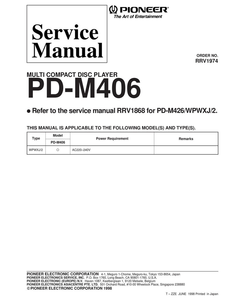
  9. Pioneer PD-41 User manual

Pioneer PD-41 User manual

This manual suits for next models

1

Other Pioneer CD Player manuals

Pioneer LaserDisc CLD-D704 User manual

Pioneer

Pioneer LaserDisc CLD-D704 User manual

Pioneer LASER DISC CLD-990 User manual

Pioneer

Pioneer LASER DISC CLD-990 User manual

Pioneer PD-M601 User manual

Pioneer

Pioneer PD-M601 User manual

Pioneer LaserDisc CLD-1450 User manual

Pioneer

Pioneer LaserDisc CLD-1450 User manual

Pioneer XC-LA21 User manual

Pioneer

Pioneer XC-LA21 User manual

Pioneer CDJ-500II User manual

Pioneer

Pioneer CDJ-500II User manual

Pioneer CLD-97 User manual

Pioneer

Pioneer CLD-97 User manual

Pioneer PD-7500 User manual

Pioneer

Pioneer PD-7500 User manual

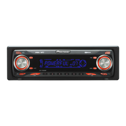
Pioneer Super Tuner IIID DEH-P5800MP User manual

Pioneer

Pioneer Super Tuner IIID DEH-P5800MP User manual

Pioneer PD-S703 User manual

Pioneer

Pioneer PD-S703 User manual

Pioneer CDJ800Mk1 User manual

Pioneer

Pioneer CDJ800Mk1 User manual

Pioneer CDJ-800 User manual

Pioneer

Pioneer CDJ-800 User manual

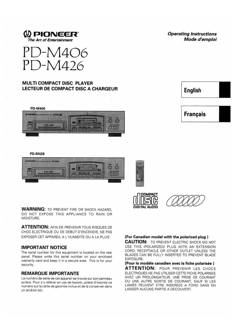
Pioneer PD-M406 User manual

Pioneer

Pioneer PD-M406 User manual

Pioneer FH-P4000R X1N User manual

Pioneer

Pioneer FH-P4000R X1N User manual

Pioneer PD-M510 User manual

Pioneer

Pioneer PD-M510 User manual

Pioneer PD-217 User manual

Pioneer

Pioneer PD-217 User manual

Pioneer PD-202 User manual

Pioneer

Pioneer PD-202 User manual

Pioneer CLD-1030 User manual

Pioneer

Pioneer CLD-1030 User manual

Pioneer PD-F1009 - CD Changer User manual

Pioneer

Pioneer PD-F1009 - CD Changer User manual

Pioneer CLD-900 Manual

Pioneer

Pioneer CLD-900 Manual

Pioneer PD-F605 User manual

Pioneer

Pioneer PD-F605 User manual

Pioneer DEH-3300R-2 User manual

Pioneer

Pioneer DEH-3300R-2 User manual

Pioneer LD-V8000 Level I User manual

Pioneer

Pioneer LD-V8000 Level I User manual

Pioneer PD-M601 User manual

Pioneer

Pioneer PD-M601 User manual

Popular CD Player manuals by other brands

Arcam CD23 Handbook

Arcam

Arcam CD23 Handbook

Sanyo MCD-Z1F Service manual

Sanyo

Sanyo MCD-Z1F Service manual

JVC RC-ST3SL instructions

JVC

JVC RC-ST3SL instructions

Technics SL-P9066 operating instructions

Technics

Technics SL-P9066 operating instructions

Marantz HD-CD1 quick start guide

Marantz

Marantz HD-CD1 quick start guide

Sony DVP-FX850 Service manual

Sony

Sony DVP-FX850 Service manual

Philips AZ1140 Instrukcja obs?ugi

Philips

Philips AZ1140 Instrukcja obs?ugi

Alpine 7909 owner's manual

Alpine

Alpine 7909 owner's manual

JVC CH-X350 instructions

JVC

JVC CH-X350 instructions

RCA RP-7923 instruction manual

RCA

RCA RP-7923 instruction manual

Philips Shockproof AX2102 brochure

Philips

Philips Shockproof AX2102 brochure

Philips CD582 user manual

Philips

Philips CD582 user manual

Philips AZ 6821 operating manual

Philips

Philips AZ 6821 operating manual

Lasonic MSU-2020 user manual

Lasonic

Lasonic MSU-2020 user manual

Denon DCD-1420 Service manual

Denon

Denon DCD-1420 Service manual

Panasonic SJ-MR100 operating instructions

Panasonic

Panasonic SJ-MR100 operating instructions

Onkyo DX-7210 instruction manual

Onkyo

Onkyo DX-7210 instruction manual

Cambridge Audio SONATA CD30 manual 

Cambridge Audio

Cambridge Audio SONATA CD30 manual 

manuals.online logo
manuals.online logoBrands
  • About & Mission
  • Contact us
  • Privacy Policy
  • Terms and Conditions

Copyright 2025 Manuals.Online. All Rights Reserved.

@)
PIONEER’
The
Art
of
Entertainment
e1vice
ORDER
NO.
ARP2297
COMPACT
DISC
PLAYER
PD-4
1
PD-9700
PD-41
AND
PD-9700
HAVE
THE
FOLLOWING
:
Model
:
Type
Power
Requirement
Remarks
PD-41
PD-9700
AC
220
V-230
V,
AC
230
V-240
V(switchable)*
AC
110
V,
120
V-127
V,
220
V,
240
V(switchable)
*
Change
the
connection
of
the
power
transformer's
primary
wiring.
@
This
manual
is
applicable
to
PD-41/KU,
PD-9700/KC,
HEM,
HB
and
SD
types.
@
Asto
the
PD-9700/KC,
HEM,
HB
and
SD
types,
refer
to
page
84.
©
Asto
the
disassembly
and
mechanism
descriptions,
refer
to
the
PD-41,
PD-9700
service
guide(ARP2318).
@
Ce
manuel
pour
le
service
comprend
les
explications
de
reglage
en
francais.
e
Este
manual
de
servicio
trata
del
metodo
ajuste
escrito
en
espanol.
CONTENTS
ele
SAFETY
INFORMATION
settais
detaeade
ine
renbedenee
av
eeesnalees
2
6.
REGLAGE
Perr
rrr
rer
reer
errr
errr
r
er
ee
eee
rere
rrr
errr
rere
e
red)
50
2.
EXPLODED
VIEWS
AND
PARTS
LIST
vrvvrrrrereeeeeterees
4
6.
AJUSTE
teccccecteteeeee
terete
enn
ee
etn
ee
enn
eeenee
settee
tea
eenes
66
BZ
PACKING
covcccceccecceceeeeteereeeeeseseseeseeseaeeeeeerenren
gees
11
T.IC
INFORMATION
cccccccetecrtecreseneer
eter
ettetaneeearecenas
82
4.
SCHEMATIC
DIAGRAM
AND
vvvsersrseceseeeeeesteseeees
12
8.
FOR
PD-9700/KC,
HEM,
HB
AND
SD
TYPES
84
P.C.BOARDS
CONNECTION
DIAGRAM
9,
PANEL
FACILITIES
<-1-::2ses0eseseeeseeseeessenenettttcee
86
5B.
P.C.B'SPARTS
LIST
cecceccceeeceecteeeecee
ee
eteeteueeeseenaes
32
10.
SPECIFICATIONS
cccceccerceteeceereeereca
reste
eseenneeen
rene
88.
6.
ADJUSTMENTS
crrreereeeeretretsrrtreteetee
eer
ereeeeaee
35
PIONEER
ELECTRONIC
CORPORATION
4-1,
Meguro
1-Chome,
Meguro-ku,
Tokyo
153,
Japan
PIONEER
ELECTRONICS
SERVICE
INC.
P.O.
Box
1760,
Long
Beach,
California
90801
U.S.A.
PIONEER
ELECTRONICS
OF
CANADA,
INC.
505
Cochrane
Drive,
Markham,
Ontario
L3R 8E3
Canada
PIONEER
ELECTRONIC
[EUROPE]
N.V.
Keetberglaan
1,
9120
Beveren,
Belgium
PIONEER
ELECTRONICS
AUSTRALIA
PTY. LTD.
178-184
Boundary
Road,
Braeside,
Victoria
3195,
Australia
TEL:
[03]
580-9911
©
PIONEER
ELECTRONIC
CORPORATION
1991
FI
JUNE
1991
Printed
in
Japan
This
service
manual
is
intended
for
qualified
service
technicians;
it
is
not
meant
for
the
casual
do-it-yourselfer.
Qualified
technicians
have
the
neces-
sary
test
equipment
and
tools,
and
have
been
trained
to
properly
and
safely
repair
complex
products
such
as
those
covered
by
this
manual.
Improperly
performed
repairs
can
adversely
affect
the
safety
and
reliability
of
the
product
and
may
void
the
warranty.
If
you
are
not
qualified
to
perform
the
repair
of
this
product
properly
and
safely,
you
should
not
risk
trying
to
do
so
and
refer
the
repair
to
a
qualified
service
technician.
WARNING
Lead
in
solder
used
in
this
product
is
listed
by
the
California
Health
and
Welfare
agency
as
a
known
reproductive
toxicant
which
may
cause
birth
defects
or
other
reproductive
harm
(California
Health
&
Safety
Code,
Section
25249.5).
When
servicing
or
handling
circuit
boards
and
other
components
which
contain
lead
in
solder,
avoid
unprotected
skin
contact
with
the
solder.
Also,
when
soldering
do
not
inhale
any
smoke
or
fumes
produced.
1.
SAFETY
INFORMATION
(FOR
USA
MODEL
ONLY)
1.SAFETY
PRECAUTIONS
The
following
check
should
be
performed
for
the
continued
protection
of
the
customer
and
service
technician.
LEAKAGE
CURRENT
CHECK
Measure
leakage
current
to
a
known
earth
ground
(water
pipe,
conduit,
etc.)
by
connecting
a
leakage
current
tester
such
as
Simpson
Model
229-2
or
equivalent
between
the
earth
ground
and
all
exposed
metal
parts
of
the
appliance
(input/output
terminals,
screwheads,
metal
overlays,
control
shaft,
etc.).
Plug
the
AC
line
cord
of
the
appliance
directly
into
a
120V
AC
60Hz
outlet
and
turn
the
AC
power
switch
on.
Any
current
measured
must
not
exceed
0.5mA.
A
Reading
should
Ceakage
|
Not
be
above
current
|
0-5mA
Device
under
test
Test
ail
exposed
metal
surfaces
2-wire
cord
Also
test
with
plug
reversed
(Using
AC
adapter
ground
plug
as
required)
©
ANY
MEASUREMENTS
NOT
WITHIN
THE
LIMITS
OUTLINED
ABOVE
ARE
INDICATIVE
OF
A
PO-
TENTIAL
SHOCK
HAZARD
AND
MUST
BE
COR-
RECTED
BEFORE
RETURNING
THE
APPLIANCE
TO
THE
CUSTOMER.
:
2.PRODUCT
SAFETY
NOTICE
Many
electrical
and
mechanical
parts
in
the
appli-
ance
have
special
safety
related
characteristics.
These
are
often
not
evident
from
visual
inspection
nor
the
protection
afforded
by
them
necessarily
can
be
ob-
tained
by
using
replacement
components
rated
for
vol-
tage,
wattage,
etc.
Replacement
parts
which
have
these
special
safety
characteristics
are
identified
in
this
Service
Manual.
Electrical
components
having
such
features
are
identified
by
marking
with
a
A
on
the
schematics
and
on
the
parts
list
in
this
Service
Manual.
The
use
of
a
substitute
replacement
component
which
dose
not
have
the
same
safety
characteristics
as
the
PIONEER
recommended
replacement
one,
shown
in
the
parts
list
in
this
Service
Manual,
may
create
shock,
fire,
or
other
hazards.
Product
Safety
is
continuously
under
review
and
new
instructions
are
issued
from
time
to
time.
For
the
latest
information,
always
consult
the
current
PIONEER
Service
Manual.
A
subscription
to,
or
ad-
ditional
copies
of,
PIONEER
Service
Manual
may
be
obtained
at
a
nominal
charge
from
PIONEER.
AC
Leakage
Test
;
{FOR
EUROPEAN
MODEL
ONLY)
VARO!
AVATTAESSA
JA
SUOJALUKITUS
OHITETTAESSA
OLET
ALTTIINA
NAKYMATTOMALLE
LASERSATEILYLLE.
ALA
KATSO
SATEESEEN.
PD-41,
PD-9700
WARNING!
DEVICE
INCLUDES
LASER
DIODE
WHICH
EMITS
INVISIBLE
INFRARED
RADIATION
WHICH
IS
DANGEROUS
TO
EYES.
THERE
IS
A
WARNING
SIGN
ACCORDING
TO
PICTURE
LASER
1
INSIDE
THE
DEVICE
CLOSE
TO
THE
LASER
LASER
Kuva
1
DIODE.
Picture
1
Lasersateilyn
Warning
sign
for
[
ADVERSEL:
varoitusmerkki
laser
radiation
USYNLIG
LASERSTRALING
VED
ABNING
NAR
SIKKERHEDSAFBRYDERE
ER
UDE
AF
FUNKTION
UNDGA
UDSAETTELSE
FOR
STRALING.
IMPORTANT
THIS
PIONEER
APPARATUS
CONTAINS
LASER
OF
HIGHER
CLASS
THAN
1.
SERVICING
OPERATION
OF
THE
APPARATUS
SHOULD
BE
DONE
BY
A
SPECIALLY
r
VARNING!
INSTRUCTED
PERSON.
OSYNLIG
LASERSTRALNING
NAR
DENNA
DEL
AR
OPPNAD
OCH
SPARREN
AR
URKOPPLAD.
BETRAKTA
EJ
STRALEN.
LASER
DIODE
CHARACTERISTICS
MAXIMUM
OUTPUT
POWER:
5
mw
WAVELENGTH:
780-785
nm
LABEL
CHECK
HEM
and
HB
types
HEM
type
_—_ADVARSEL
USYNUG
LASERSTRALING
VED
ABMING
NAA
SIKKERHED
SAF-
BAYDERE
ER
UDE
AF
FUNTION.
UNOGA
UOSATTELSE
FOR
STRALING.
CLASS
1
LASER
PRODUCT
VAW-
328
VORSICHT!
UNSICHTBARE
LASER-STRAHLUNG
TRITT
AUS,
WEIN
OECKEL
(OER
KLAPPE)
GEOFFNET
IST!
NICHT
OEM
STRAHL
AUSSETZEN!
VRW1034
Additional
Laser
Caution
1.
Laser
Interlock
Mechanism
The
position
of
the
switch
(S
601)
for
the
detecting
loading
completion
is
detected
by
the
system
microprocessor,
and
the
design
prevents
laser
diode
oscillation
when
the
switch
(S
601)
is
not
in
CLMP
terminal
side
(when
the
mechanism
is
not
clamped
and
CLMP
signal
is
high
level).
Thus,
the
interlock
will
no
longer
function
if
the
switch
(S601)
is
deliberately
set
to
CLMP
terminal
side
(if
CLMP
signal
is
low
level).
In
the
test
mode,
the
interlock
mechanism
will
not
function
(refer
to
page
36).
Laser
diode
oscillation
will
continue
if
pins
2
and
3
of
CXA
1471S
(IC
101)
are
connected
to
ground
or
pin
20
is
connected
to
high
level(ON)
or
the
terminals
of
Q
101
are
shorted
to
each
other(fault
condition).
VARO!
Avattaessa
ja
suojalukitus
ohitetta-
assa
olet
alttiina
nakymattémalle
lasersdteilylle.
Ala
katso
sdteeseen.
VARNING!
Osynlig
laserstrdlning
nar
denna
del
Ar
Oppnad
och
sparren
4r
urkopplad.
Betrakta
ej
strdlen.
PRW1233
CAUTION
INVISIBLE
LASER
RADIATION
WHEN
OPEN,
AVOID.
EXPOSURE
TO
BEAM
HB
type
ad
When
the
cover
is
opened,
close
viewing
of
the
objective
lens
with
the
naked
eye
will
cause
exposure
to
PRW1018
a
Class
1
or
higher
laser
beam.
HEM
type
2.
EXPLODED
VIEWS
AND
PARTS
LIST
NOTES:
e
Parts
without
part
number
cannot
be
supplied.
¢
Parts
marked
by
“®”
are
not
always
kept
in
stock.
Their
delivery
time
may
be
longer
than
usual
or
they
may
be
unavailable.
e
The
A
mark
found
on
some
component
parts
indicates
the
importance
of
the
safety
factor
of
the
part.
Therefore,
when
replacing,
be
sure
to
use
parts
of
identical
designation.
2.1
EXTERIOR
Parts
List
of
Exterior
Mark
No.
Description
Parts
No.
Mark
No.
Description
Parts
No.
A®
1
Analog
board
assembly
PWM1490
41
Bonnet
case
PYY1071
A
2
Strain
rerief
CM-22C
A\®
=
42:
Main
board
assembly
PW2Z2150
3
33P
F.F.C/30V
PDD1094
©
43
Function
A
board
assembly
PWZ2168
A
4
AC
power
cord
PDG1015
44
Badge
A
5
Power
transformer
PTT1166
45
Front
panel
A
6
Power
transformer
PTT1206
46
Function
B
board
assembly
7
Washer
ABE1009
47
Primary
board
assembly
8
Stopper
PNM1095
48
Rubber
sheet
9
Tape
PNM1099
49
Switch
angle
10
Stopper
PNM1107
50
Spacer
11
Cord
clamper(steel)
RNH-184
51
L
angle
12
Button
PAC1530
52
Sheet
13
Power
button
PAC1539
53
Tape
14
Control
button
PAC1609
54
Side
angle
15
FL
sheet
PAM1514
55
PCB
angle
16
Display
window
PAM1515
56
Under
base
17
LED
cover
PEB1150
57
Base
18
LED
cover
(S)
PEB1167
58
Rear
base
‘
19
Side
rubber
PEB1180
59
Binder
holder
20
Tray
panel
PNW1815
60
PCB
spacer
21
Lens
L
PNW1860
61
Angle
B
22
Indicator
lens
PNW1893
62
Shield
angle
23
Tray
lens
PNW1950
63
Shield
plate
24
Control
panel
PNW
2066
25
7.
8 © ©
26
Screw
BBT30P080FCC
27
Screw
BBZ26P080FCC
28
Screw
BBZ30P080FCC
29
Screw
BBZ30P080FCC
30
Screw
BBZ30P140FCC
31
Screw
BBZ40P060FCC
32
Screw
BBZ40P080FZK
33
Screw
FBT40P080FZK
34
Screw
IBZ30P060FCC
35
Screw
IBZ30P150FCC
36
Screw
IBZ30P180FCC
37
Screw
PDZ30P050FCC
38
Screw
PMZ30P060FCC
39
Washer
WH40FUC
40
Front
panel
assembly
PEA1167
2.2
MECHANISM
SECTION
Parts
List
of
Mechanism
section
Mark
No.
Description
Lever
switch
Screw(steel)
Rubber
belt
Motor
pulley
Drive
gear
Timing
lever
Gear
pulley
SW
head
Float
base
Left
cam
Right
cam
Compression
spring
Tention
spring
Float
(rubber)
Table
rubber
sheet
Tray
Table
guide
Lock
plate
DC
motor(0.75W)
Rubber
bush
Rubber
bush
Screw
Screw
Screw
Screw
Stop
ring
Turn
table
assembly
Push
switch
Spring
Speing
Plate
spring
Belt
(square)
Screw
Guide
bar
Pulley
Half
nut
Motor
pulley
Screw
DC
motor(1.7W)
Screw
Screw
Screw
Screw
Pick
up
assembly
DC
motor
assembly
(With
oil)
Semi-fixed
VR(3.3K)
Caution
label
Disc
table
Parts
No.
DSK1003
PBA1027
PEB1186
PNW1634
PNW1996
PNW1997
PNW1998
PNW1999
PNW2000
PNW2001
PNW2002
PBH1120
PBH1121
PEB1014
PEB1169
PNW2003
PNW2004
PNW2005
:
PXM1010
PEB1031
PEB1170
BMZ26P040FMC
BPZ26P060FMC
BPZ26P060FMC
IPZ20P080FMC
YE20S
PEA1157
DSG1014
PBH1009
PBH1084
PBK1057
PEB1072
PLA1003
PLA1071
PNW1066
PNW1605
PNW1634
PBZ30P080FMC
PXM1013
BPZ20P080FZK
JFZ20P025FMC
PBZ30P060FMC
PMZ20P030FMC
PEA1030
PEA1156
PCP
1008
PRW1344
PNW1067
Mark
No.
Description
Parts
No.
101
Shaft
holder
102
Loading
base
103
Table
bearings
assembly
104
Servo
mechanism
assembly
105
Earth
lead
unit(300V)
106
Motor
base
107
Mechanism
base
108
Mechanism
chassis
109
Clamper
110
Connector
assembly
111
Turn
table(AL)
e
How
to
install
the
disc
table
[1]
Use
nippers
or
other
tool
to
cut
the
two
sections
marked
@
in
figure
(1].
Then
remove
the
spacer.
[2]
While
supporting
the
spindle
motor
shaft
with
the
stopper,
put
spacer
on
top
of
the
motor
base
(angled
so
it
doesn’t
touch
section
®),
and
stick
the
disc
table
on
top
(takes
about
9kg
pressure).
Take
off
the
spacer.
(1]
Spindle
motor
mounting
position
Spacer
G
(pressure
of
bout
9kg)
Chassis
Disc
table
7.3mm
3.
Sem
Motor
59
g5mm
base
Spacer
setting
position
Stopper
2.3
REMOVE
THE
TRAY
PANEL
AND
THE
TRAY
LENS
Hold
the
tray
panel
with
your
hands
as
the
figure
shown
right,
and
grasp
the
tray
with
your
thumbs
and
then
lift
the
tray
panel
up
while
pulling
it
toward
you
with
the
other
fingers.(Figs
.
1
and
2)
2.4
INSTALL
THE
TRAY
PANEL
AND
THE
TRAY
LENS
Align
the
tray
panel
with
the
grooves
located
at
both
edges
of
the
tray
while
holding
the
tray
lens
with
you
fingers,
and
then
press
it
down
till
it
stops.
(Fig.
3)
Hold
the
tray
panel
and
the
tray
as
shown
in
Fig.
4
and
slide
them
down
till
you
hear
a
click
sound
while
pressing
strongly
with
your
thumbs.
(Figs.
4
and
5)
Fig.
4
Tray
panel
Fig.
3
Tray
panel
Push
strongly
Slide
down
y
while
pressing
Fig.
5
1G
2.3
REMOVE
THE
TRAY
PANEL
AND
THE
3.
PACKING
___PartsNo.
TRAY
LENS
Mark
No.
Description
Parts
No.
Hold
the
tray
panel
with
your
hands
as
the
figure
shown
1
Cord
with
plug(mini
plug)
PDE-319
:
:
:
2
Cord
with
plug
PDE1001
right,
and
grasp
the
tray
with
your
thumbs
and
then
lift
the
3:
Operating
instrucvons
PRE1149
tray
panel
up
while
pulling
it
toward
you
with
the
other
(English,
French)
,
4
Remote
control
unit(CU-PD054)
=
PWW1058
fingers.
(Figs
.
1
and
2)
5
Battery
cover
PZN1001
6
Polyethelene
bag
221-038
7
Protector
F
PHA1145
8
Protector
R
PHA1146
9
CD
packing
case
PHG1677
10
Sheet
VHL-037
11
Label
PRW1253
101
Battery
(R03,
AAA)
ql
i
|
|
1
2
2.4
INSTALL
THE
TRAY
PANEL
AND
THE
table
TRAY
LENS
y
cut
the
two
sections
n
remove
the
spacer.
Align
the
tray
panel
with
the
grooves
located
at
both
edges
of
the
tray
while
holding
the
tray
lens
with
you
fingers,
and
ile
motor
sh
i
Or
Shatin
then
press
it
down
till
it
stops.
(Fig.
3)
op
of
the
motor
base
section
®),
and
stick
about
9kg
pressure).
Hold
the
tray
panel
and
the
tray
as
shown
in
Fig.
4
and
<
3
slide
them
down
till
you
hear
a
click
sound
while
pressing
strongly
with
your
thumbs.
(Figs.
4
and
5)
Spacer
Tray
panel
(pressure
of
about
9kg)
$
Disc
table
Fig.
3
Tray
panel
Push
strongly
NY
mK
Y
Ps
Slide
down
$
i
while
pressing
4
IN
Fig.
4
Fig.
5
3
1c
eTERMINAL
VOLTAGES
1C101
(CXA1471S)
[rou
[Bt
|
tse
0026
°-ad
‘Lp-dd
1C151
(CXA13725S)
fet
|
ee
TRY
|
ve
HB
|r|
ec
ee
1
reps
Pate
oT]
ao
feo
fees
[oe [=s
cE
106301
eA
2.
5
0
5
5
5
10401
(PD4329A)
fia?
[voitase
[48
|
vortase
[fa
|
vorease_|
Pajoe.
2
tle
a
Se
eee
Pafussarfie[-s
fast
sei
r[-amntes
|
eo|-nmem—neae]
0
feet
5
|
Vs
[omens
ferent
farts
ssp
3
Cs
[-uaai
[ee
[-esmie|
se]
5
Pees
[remawns
[es
[eae
ta
foe]
a
[est
8
=uaatas
ee
[—4
=—7
[ao]
0
[ae
ye
Presa
Tepe
tet
=
Pri[eemnees
fet[-1.8
jas]
6
[531
ie
a
ES
SST
CE
s§
ee
ew
ecneh
to
a
Prep
_[s0[-ai=aine]
ee]
5
[62
ET
Se
fre[-ms~—mepaef
saat
«oO
}
CO
PO-41,PD-93700
|
4.
SCHEMATIC
DIAGRAM
AND
P.C.BOARDS
CONNECTION
DIAGRAM
4.1
MAIN
BOARD(PWZ
2150),
PRIMARY
BOARD,
FUNCTION
A
BOARD(PWZ
2168),
AND
FUNCTION
B
BOARD
ASSEMBLIES
|
ee
ee
|
SERVO
MECHANISM
ASSEMBLY
|
‘
fF
a
A)
a
ge,
See
oe
yg
er
re
eae
rae
©OMOOODO
Si.
es
OOOO
|
[ea
te
ee
ake
7
|
R105
al
3
PICK
UP
ASSEMBLY
cateenee
Seok
CN201
|
PEA1030
|
DS
Sede
I4\
|p335|
ovci2ses
!
4
wos
Z°e\
|
10
&
R10
“x
x
R3
7
we
fe
Pl
roe
ie
+
[C101
V+SA
@
osTL
[or
y
CXA1471S
R102
,
|
2
.
wn
5.6K
FF
[UPd
‘cor’
w
(RF
AMP)
-8
DIGITAL
OFF
|
Qa
LOG
a
2u
348
z
!
to
z
ee ee
ee
TRACK
ING
le
COIL
|
D,
|
Bt
Iwo
0
os
!
ae
eae
CXD2500AQ
&
|
B
(DECODER)
to)
Or
c102
|
|
eo
eas
1220/25
pan
vo
ae
a
Gis
|
ShoQe
8255038
er
GA
VUAQOUyg)
8ROr—O
>
:
ot
o>
2
22
w
—
Ao
Se
Sara
oa
|
eee
ri
|
4
1
(3
y
x
|
o.c0z7
2
pry)
Ei
=
o
w
:
a
ckameraa
ee
z
|
R212
120K!
(spINDLE
ORIVE)
pea
GND
hin
[<x
—
|
INSIDE
Sw
cael
|
|
i
;
me
|
oe
|
:
CN202
Seah
a3
SPINDLE
MOTOR
:
xT
BRK
1 1
ASSEMBLY
—
<_
:
:
MN
a
PEAI156
:
(GD
LINSO
“
+o
(te
.
|
3
|
)
rae
|
$s
|
24
B)
6)
4
16202
(1/2)
G1
Pcie]
ence
oy
n
_.
&S)
(4)
3
5
(FOCUS
DRIVE)
|
‘
Pee
:
&
a
C
i
es
4)
Be
©,
a
14
eos
|
MUTE
Zz
O
bod
z
CARR
LAGE
MOTOR
|
i
|
He
101
z
L
amon
4
ele
:
Ww
ee
aR
See
7
Cle
Q
=
$601
|
=x
[|e
E
A
DSk1003
|
rat
aN
r
CLAM
rs)
O
i
opiate
eee
ne
;
©
(2)
>
Ww
O
\
a
N¢
ex]
1
(3)
re
—
3
a
Ie
see
eee
|
YW
+
U
7
|
(™)
oe
ae
.
|
ie
|
|
O
PXM1
010
|
|
LOAD
ING
MOTOR
|
|
|
Rif
jee
ee
}
|
es
| | |
un
| i
ut
=
EER
at
a)
erg
ean
eee
:
O
D
a
IC
—
=
Y=]
$R210
201
(173)
Sea)
ok”
LAGS20
R206,
pVtSA
|
Nove
or
(CARRIAGE
DRIVE)
390K
x
|
ro)
v-8
GA
a0
x
YX
$
Fi
x
1.RESISTORS
:
|
GDR
R222
fo]
eer
sin
yee
Indicated
in
$2,
1/4W,
1/6W
and
1/8W,
+5%
tolerance
unless
otherwise
|
R221
&
97
GND
noted
k;
k92,M;
M&,
(F);
£1%,
(G);
+2%,
(K);
£10%,
|
100K
LouT
GA
o
CA
(M);
+£20%
tolerance.
|
|
700K
2.CAPACITORS
:
|
paee
AIC201
(2/73)
—
ndicated
in
capacity
(yzF)
/voitage'
unless
otherwise
noted
p;
pF.
RESET
Indicated
i
ity
(uF)
/voltage(V)
unless
otherwise
noted
p;
pF.
|
faoK
LAGS20
V+5
V+5
Indication
without
voltage
is
50
V
except
electrolytic
capacitor.
GND
(LOADING
DRIVE)
1c60
@
M51957AL
j
3.VOLTAGE,
CURRENT
:
(BL
12
eek
ner
\__]
;
DC
voltage
(V)
at
play
state.
RE2
°
5
<mA_;
DC
current
at
play
state.
fl
22K
e
Value
in
(
)
is
DC
current
at
stop
state.
|
j
R63
ia
ne
410K
bo
4.OTHERS
:
oe
a
=>
;
Signal
route.
GND
@
;
Adjusting
point
E
The
/\
mark
found
on
some
component
parts
indicates
the
inportance
of
the
safety
factor
of
the
part.
Therefore,
when
replacing,
be
sure
to
use
parts
of
identical
designation.
|
3X
marked
capacitors
and
resistors
have
parts
numbers.
|
This
is
the
basic
schematic
diagram,
but
the
actual
circuit
may
|
vary
due
to
improvements
in
design.
|
MA
I
N
B
OAR
D
AS
S
E
MB
LY
5.
SWITCHES
:
(The
underlined
indicates
the
switch
position)
|
ea
nee
aes
=
PRIMARY
BOARD
ASSEMBLY
Ee
ees
—
S1
POWER
|
N
gg
FUNCTION
A
BOARD
ASSEMBLY
|
$401
DO
|
caoz
Kid
__)
TRACK
SEARCH
|
!
et
addy
tua
|
a
eM
qqa9g294a
$403
PAUSE({I])
;
a
.
S404
PLAY(D)
|
Es
L
|
$—
Lo
$405
OPEN/CLOSE(A)
L————————————
OAOMADOO@O@OOCOHODOOOOOCOOOOOOHOOHOPOOSOHSSHOOOO+t--
$406
STOP(C))
CN351
KU,
KC
ONLY
*1
fF
FUNCTION
B
BOARD
ASSEMBLY
es
RERAUDIO
SIGNAL
Loo
N51
S407
DISPLAY
OFF
-
;
bre
tl
KS;
HLEMESS.
$408
OUTPUT
—2—
FOCUS
SERVO
SIGNAL
(HEM,
HB,
SD
|
HLEMS1
5:
—
TRACKING
SERVO
SIGNAL
—S
-SPINDLE
MOTOR
SERVO
SIGNAL
—S—
-CARRIAGE
MOTOR
SERVO
SIGNAL
—bL—
-LOADING
MOTOR
SERVO
SIGNAL
12
=—E
a
Py
2
1
3
1
a
t