manuals.online logo
Brands
  1. Home
  2. •
  3. Brands
  4. •
  5. Pioneer
  6. •
  7. CD Player
  8. •
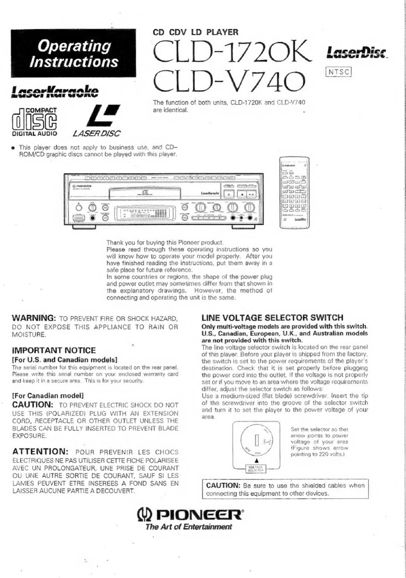
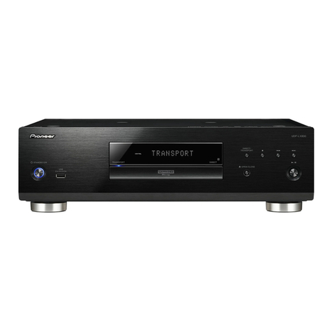
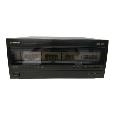
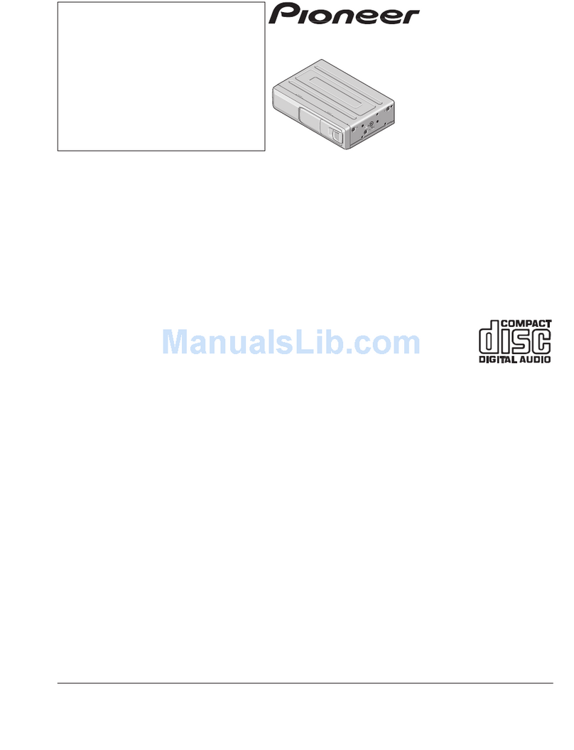
  9. Pioneer PD-T507 User manual

Pioneer PD-T507 User manual

U
PIONEER
The
Art
of
Entertainment
www.rtvcenter.com
repairtips,
servicemanuals
forum,
chassispictures.
.
.
Service
———
=———
=
ORDER
NO.
+
The
above
illustration
shows
the
PD-T507.
ARP2201
O7
O7
TWIN-TRAY
COMPACT
DISK
PLAYER
PD-T5
PD-T3
PD-T507
AND
PD-T307
HAVE
THE
FOLLOWING:
|
Model
Type
—
Power
Requirement
Remarks
PD-T507
PD-T307
KC
O
|
O
AC120V
only
MEM
O
O
AC220V-230V
u
=
=
E
+
=
—
UB
O
AC230V-240V
UPW
O
O
AC230V-240V
i
|
AC110V,
120V-127V,
220V,
240V
y
o
SD
(switchable)
O
This
manual
is
applicable
to
the
PD-T507/KC,
MEM,
UB,
PD-T307/KC
and
MEM
types.
O
As
to
the
PD-T507/MEM,
UB
and
PD-T307/MEM
types,
refer
to
page
93-94.
@
As
to
the
other
types,
refer
to
applicable
service
manuals.
O
As
to
the
mechanism
descriptions,
refer
to
the
PD-Z74T
service
guide
(ARP2144).
O
Ce
manuel
pour
le
service
comprend
les
explications
de
réglage
en
français.
O
Este
manual
de
servicio
trata
del
método
ajuste
escrito
en
español.
PIONEER
ELECTRONIC
CORPORATION
4,
Meguro
1-Chome,
Meguro-ku,
Tokyo
153,
Japan
PIONEER
ELECTRONICS
SERVICE
INC.
P.O.
Box
1760,
Long
Beach,
California
90801
U.S.A
PIONEER
ELECTRONICS
OF
CANADA,
INC.
505
Cochrane
Drive,
Markham,
Ontario
L3R 8E3
Canada
PIONEER
ELECTRONIC
[EUROPE]
N.V.
Keetberglaan
1,
2740
Beveren,
Belgium
PIONEER
ELECTRONICS
AUSTRALIA
PTY.
LTD.
178-184
Boundary
Road,
Braeside,
Victoria
3195,
Australia
TEL:
[03]
580-9911
©
PIONEER
ELECTRONIC
CORPORATION
1991
SO
MAR.
1991
Printed
in
Japan
2.
REMOVING
AND
MOUNTING
OF
EACH
BLOCK
@
REMOVAL
OF
TRAY
|
AND
TRAY
II
1.
Open
the
tray
I.
2.
Insert
the
flat
blade
screwdriver
into
the
slit
in
the
left
of
tray
I.
Pull
out
the
tray
I
by
pushing
the
screwdriver.
Screwdriver
Slit
position
of
tray
|
*
When
remove
the
tray
Il,
open
it
first,
insert
the
flat
blade
screwdriver
into
the
slit
in
the
right
of
tray
Il,
and
pull
out
the
tray
by
pushing
the
screwdriver.
Screwdriver
Gear
Il
Slit
position
of
tray
Il
Fig.
1
O
MOUNTING
OF
TRAY
|
1.
Set
the
disc
II
to
the
clamp
position
and
open
the
tray
I.
2.
Align
the
Ist
tooth
of
tray
I
to
ungrooved
portion
of
gear
I,
and
insert
the
tray
I.
+
mark
ik
Ungrooved
portion
:
+
mark
ae
1st
tooth
Fig.
2
@
MOUNTING
OF
TRAY
II
1.
Set
the
disc
I
to
the
clamp
position
and
open
the
tray
II.
2.
Align
the
Ist
tooth
of
tray
II
to
[]
marked
position
of
gear
II,
and
insert
the
tray
II.
Align
horizontally
to
[]
mark.
1st
tooth
Fig.
3
@
MOUNTING
AND
POSITIONING
OF
MAIN
CAM,
FOLLOW
GEAR,
GEAR
|
AND
GEAR
II
Set
the
following
gears
to
the
position
as
shown
by
arrows.
Protrusion
Gear
|
Gear
Il
Main
cam
Follow
gear
Follow
gear
Fig.
4
@
MOUNTING
OF
CLAMPER
ASSEMBLY
Mount
the
clamper
assembly
by
aligning
the
protrusion
portion
as
shown
in
the
figure.
Protrusion
Fig.
5
@
REMOVING
THE
BONNET
1.
Remove
six
screws
to
the
bonnet.
2.
Remove
the
bonnet
by
pulling
up
it
in
the
vertically
direction
of
arrow.
To
easily
remove
the
bonnet,
pull
outward
on
both
sides
of
the
bonnet
then
pull
it
diagonally
toward
the
rear
of
the
unit.
Note:
If
you
pull
up
the
rear
base
of
the
bonnet
to
remove
it
as
in
the
conventional
manner,
the
hooks
shown
in
Fig.
6
may
be
caught
and
the
hooks
on
the
front
panel
side
may
be
deformed.
Nail
section
Front
panel
A
Fig.
6
www.rtvcenter.com
repairtips,
servicemanuals
forum,
chassispictures.
.
.
PD-T507,
PD-T307
3.
PACKING
Parts
List
(For
PD-T507/KC
and
PD-T307/KC
types)
vertically
Mark
No.
Description
Part
No.
h
sides
of
1
Protector
(F)
PHA1116
f
the
unit.
2
Protector
(R)
PHA1117
move
it
as
3
Packing
case
PHG1072
in
Fig.
6
(For
PD
-
T507)
:
j
Packing
case
PHG1701
[side
may
(For
PD
—
T307)
4
Sheet
Z23
—
007
5
Connection
cord
PDE
-
319
(with
mini
plug)
6
Connection
cord
PDE1109
7
Operating
instructions
PRE1143
(English
/French)
mA
8
Remote
control
unit
PWW1062
By
(CU
-
PD047)
i
(For
PD
—
T507)
9
Battery
cover
PZN1010
(For
PD
-
T507)
101
Battery
(R03,
AAA)
]
(For
PD
—
T507)
==]
PD-T507,
PD-T307
Exterio
NOTES:
e
Parts
without
part
number
cannot
be
supplied.
A
e
The
A\
mark
found
on
some
component
parts
indicates
the
importance
of
the
safety
factor
of
the
part.
Therefore,
when
replacing,
be
sure
to
use
parts
of
identical
designation.
e
Parts
marked
by
“
©”
are
not
always
kept
in
stock.
Their
delivery
time
may
be
longer
than
usual
or
they
may
be
unavailable.
4.1
EXTERIOR
Parts
List
(For
PD-T507/KC
and
PD-T307/KC
types)
—
Mark
No.
Description
Part
No.
Mark
No.
Description
Part
No.
©
1
Mother
board
assembly
PWM1464
101
Sub
assembly
(For
PD
-
T507)
102
SW
assembly
©
Mother
board
assembly
PWM1460
103
Headphone
assembly
(For
PD
—
T307)
104
-Under
base
©
2
Display
assembly
PWZ2132
105
Rear
base
(For
PD
—
T507)
A
3
Strain
relief
CM
—
22C
106
Name
plate
(For
PD
—
T507)
107
Function
panel
(B)
B
A
Strain
relief
CM
—
22
(For
PD
—
T307)
.
4
31P
F.F.C/30V
PDD1074
on
A
5
AC
Power
cord
PDG1015
Note:
iad
(For
PD
—
T507)
*
1:
The
stopper
consist
of
the
big
the
re
A
AC
Power
cord
PDG1040
ring
part
and
the
small
ring
(For
PD
-
T307)
part.
If
you
stik
the
stopper
to
the
A
6
Power
transformer
PTT1187
leg,
stick
the
big
ring
part
to
u
7
Stopper
PNM1070
the
front
leg,
and
the
small
8
Insulator
VNK1095
ring
part
to
the
rear
leg.
9
Headphone
knob
PAC1370
/
10
Power
button
PAC1540
Smooth
;
7
11
Play
button
(B)
PACI547
I
12
O/C
button
PAC1548
13
Time
button
(B)
PAC1549
wer
14
Program
button
(B)
PAC1594
15
Display
window
PAM1465
ES
E
C
16
Tray
name
plate
(A)
PNW1901
(For
the
(For
the
17
Tray
name
plate
(B)
PNW1902
or
|
rear
leg)
18
LED
lens
PNW2019
front
leg)
19
Function
panel
assembly
PEA1154
20
Bonnet
PYY1147
21
Play
button
(A)
PAC1550
L
22
Track
button
PAC1579
23
Display
window
PAM1464
Ez
N
24
29P
F.F.C/30V
PDD1075
|
25
Function
panel
assembly
PEA1125
17
N
Sac
26
Leg
assembly
PXA1201
N
27
Display
assembly
PWZ2130
28
Screw
BBZ30P060FMC
--
29
Screw
BBZ30P080FZK
30
Screw
BBZ30P120FMC
D
31
Screw
FBT40P080FMC
32
Screw
IBZ30P080FCC
33
Screw
PDZ30P050FMC
34
Time
button
(A)
PAC1546
i
(For
PD
-
T307)
S
6
7
PD-T507
o
dl
For
PD-T507
them
so
that
their
smooth
sides
face
fowards
the
rear
panel,
then
insert
as
illustrated
below.
Smooth
side
Smooth
side
*3:
When
replacing
the
play
button
B
(PAC1547),
cut
both
side
tips
from
the
new
part
and
turn
Smooth
side
Note
:
*
:
(No.26),
PD
-
T307
only
*
l
:
See
page
6
7
PD-T507
only
*1l
'!
__
For
PD-T307
4
22
@
Servo
Me
b
)Servo
Mechanism
Assembly
Section
e
How
to
install
the
disc
table
[1]
Use
nippers
or
other
tool
to
cut
the
two
sections
marked
®
in
figure
[1].
Then
remove
the
spacer.
[2]
While
supporting
the
spindle
motor
shaft
with
the
stopper,
put
spacer
on
top
of
the
motor
base
(angled
so
it
doesn’t
touch
section
®),
and
stick
the
disc
table
on
top
(takes
about
9kg
pressure).
Take
off
the
spacer.
i
Spacer
Chassis
S
(pressure
of
about
9kg)
(Q
+
Disc
table
3,
5mm
position
Par
Mar
11
PD-T507,
PD-T307
Parts
List
of
Mechanism
Section
Mark
No.
Description
Clamp
spring
Lever
spring
Belt
Motor
pulley
Tray
1
Ok.
U
Ne
6
Tray
2
7
Sub
tray
8
Loading
base
9
Main
cam
10
Follow
gear
11
Gear
1
12
Gear
2
13
Idler
gear
14
Clamper
arm
U
15
Clamper
arm
B
16
Clamp
cam
17
Float
base
18
Lock
lever
19
Motor
(LOADING)
20
Floating
rubber
21
Floating
rubber
22
Screw
23
Screw
24
Screw
25
Chip
capacitor
26
Screw
27
Drive
spring
28
Plate
spring
29
Belt
30
Drive
screw
31
Guide
bar
32
Half
nut
33
Disc
table
34
Pulley
35
Earth
spring
36
Push
switch
37
Spindle
motor
assembly
(with
oil)
38
Pick
-up
assembly
39
Screw
40
Screw
41
Motor
(CARRIAGE)
42
Screw
43
Semi
—
fixed
resistor
44
Screw
45
Gear
pulley
46
Push
spring
47
Screw
48
Pulley
49
Screw
PBH1103
101
Yoke
Part
No.
Mark
No.
Description
Part
No.
PBH1104
102
PEB1106
103
PNW1634
104
PNW1839
105
Magnet
Clamper
holder
Clamper
S
Mechanism
P.C.B
assembly
PNW1840
106
PNW1841
107
PNW1842
108
PNW1843
109
PNW1844
110
Servo
mechanism
assembly
Connector
assembly
(6P)
Mechanism
chassis
Motor
base
Mechanism
base
PNW1845
111
PNW1846
112
PNW1847
PNW1850
PNW1851
Actuater
cover
Sub
plate
PNW1852
PNW2041
PNW1854
PXM1010
PEB1014
PEB1132
PBA1048
IPZ30P080F
MC
IPZ20P080F
MC
CKSYF105Z16
JFZ20P025FMC
PBH1084
PBK1057
PEB1072
PLA1003
PLA1071
PNW1605
PNW1608
PNW1634
PBH1009
DSG1014
PEA1028
PEA1030
BPZ20P080FZK
PMZ20P030FMC
PXM1013
PBZ30P080F
MC
PCP1008
PMZ26P040F
MC
PNW1848
PBH1105
IPZ30P200FMC
PNW
1066
IBZ30P120FMC
12

Other manuals for PD-T507

1

This manual suits for next models

1

Other Pioneer CD Player manuals

Pioneer DEH-P5450 User manual

Pioneer

Pioneer DEH-P5450 User manual

Pioneer CDJ-1000 User manual

Pioneer

Pioneer CDJ-1000 User manual

Pioneer Elite PD-D6-J User manual

Pioneer

Pioneer Elite PD-D6-J User manual

Pioneer DEH-P825R User manual

Pioneer

Pioneer DEH-P825R User manual

Pioneer PDR-509 User manual

Pioneer

Pioneer PDR-509 User manual

Pioneer PD-M601 User manual

Pioneer

Pioneer PD-M601 User manual

Pioneer PD-S705 User manual

Pioneer

Pioneer PD-S705 User manual

Pioneer PD-117 User manual

Pioneer

Pioneer PD-117 User manual

Pioneer DEH-P410 User manual

Pioneer

Pioneer DEH-P410 User manual

Pioneer PD-95 User manual

Pioneer

Pioneer PD-95 User manual

Pioneer LaserDisc CLD-D504 User manual

Pioneer

Pioneer LaserDisc CLD-D504 User manual

Pioneer PD-S801 User manual

Pioneer

Pioneer PD-S801 User manual

Pioneer PD-M406 User manual

Pioneer

Pioneer PD-M406 User manual
Pioneer PD-41 User manual

Pioneer

Pioneer PD-41 User manual

Pioneer CMX-5000 User manual

Pioneer

Pioneer CMX-5000 User manual

Pioneer CDJ-400 - Cd/Media Player User manual

Pioneer

Pioneer CDJ-400 - Cd/Media Player User manual

Pioneer CDX-P670UC User manual

Pioneer

Pioneer CDX-P670UC User manual

Pioneer Super Tunet IIID DEH-16 User manual

Pioneer

Pioneer Super Tunet IIID DEH-16 User manual

Pioneer CDJ-200 User manual

Pioneer

Pioneer CDJ-200 User manual

Pioneer CLD-900 User manual

Pioneer

Pioneer CLD-900 User manual

Pioneer CDJ-500II User manual

Pioneer

Pioneer CDJ-500II User manual

Pioneer CDJ-500S User manual

Pioneer

Pioneer CDJ-500S User manual

Pioneer DEH-59 User manual

Pioneer

Pioneer DEH-59 User manual

Pioneer X-CM56 User manual

Pioneer

Pioneer X-CM56 User manual

Popular CD Player manuals by other brands

Sony Walkman D-191 operating instructions

Sony

Sony Walkman D-191 operating instructions

American Audio DCD-PRO210 operating instructions

American Audio

American Audio DCD-PRO210 operating instructions

Sony CFD-770 operating instructions

Sony

Sony CFD-770 operating instructions

LENCO MCi-215 instruction manual

LENCO

LENCO MCi-215 instruction manual

METRONOME TECHNOLOGIE CD One-Signature manual

METRONOME TECHNOLOGIE

METRONOME TECHNOLOGIE CD One-Signature manual

JVC CH-X350PK Service manual

JVC

JVC CH-X350PK Service manual

Kenwood CD Series instruction manual

Kenwood

Kenwood CD Series instruction manual

Sony CFD-G550CP Service manual

Sony

Sony CFD-G550CP Service manual

NAD C 538 Quick setup guide

NAD

NAD C 538 Quick setup guide

Philips AZD102/05 quick start guide

Philips

Philips AZD102/05 quick start guide

Gemini CDX-1200 operating instructions

Gemini

Gemini CDX-1200 operating instructions

Gemini CDX 2400 operating instructions

Gemini

Gemini CDX 2400 operating instructions

Luxman D-103 Service manual

Luxman

Luxman D-103 Service manual

Monacor PA-916CD instruction manual

Monacor

Monacor PA-916CD instruction manual

Velleman HQ-Power PROCD3000 manual

Velleman

Velleman HQ-Power PROCD3000 manual

Telefunken CD-211 instruction manual

Telefunken

Telefunken CD-211 instruction manual

Sharp MD-MT90H Operation manual

Sharp

Sharp MD-MT90H Operation manual

JVC RC-BF10 Bedienungsanleitung

JVC

JVC RC-BF10 Bedienungsanleitung

manuals.online logo
manuals.online logoBrands
  • About & Mission
  • Contact us
  • Privacy Policy
  • Terms and Conditions

Copyright 2025 Manuals.Online. All Rights Reserved.