Fusion 782-6610 User manual


Read these instructions before connecting and using your Fusion™ Pure
Sine Power Inverters. Failure in observing this warning may result in
injury to persons and damage to equipment.
General safety and installation information.
Warning! The following fundamental safety measures must be observed
when using electrical equipment to avoid danger of:
- Electric shock
- Fire
- Injury
About the unit itself
- The inverter must only be used for the purpose specified by the
manufacturer.
- Do not operate the inverter if the housing of cables are damaged.
- The inverter must be positioned and secured safely in order to avoid
knocking over or dropping
- If casing needs to be opened, make sure Input cables have been
properly disconnected.
- The inverter must be kept in a safe place out of the reach of children.
- The inverter may not be operated in a damp or wet environment.
- The inverter may not be used in rooms containing flammable materials.
- Make sure the inverter is well ventilated.
- Service and repair may only be carried out by skilled persons who are
familiar with the risks involved and the relevant regulations.
Caution by installation on boats
- Incorrect installation of electrical units on a boat may lead to corrosion
of the boat. Therefore, please let a (boat) electrician carry out the
installation of the inverter.
Intended use
The inverter is suitable for e.g. high-quality appliances from the audio,
video or PC.
The output voltage corresponds to the standard one of your socket (pure
sinus-voltage).
Attention! Please note that appliances like drills, TV’s or
refrigerators require a high starting-current which is far over the
nominal current.
With its low weight and the compact design the inverter can be easily
installed into campers, commercial vehicles or motor and sailing yachts.

Required tools and installations equipment
Depending on type of installation, the following tools are required:
-set of screw drivers
-drill and set of bits
-wrench
-crimping shears for the12/24V wire connection
For connection of inverter to the battery, the following cable connecting
hardware is needed:
-2 different flexible cable connections.
-Various terminals, multi-core cable ends
Caution:
Before drilling any mounting holes, make sure that there are no wires,
fuel lines or tanks directly below the surface being drilled.
Installation
The inverter has to be installed in a dry and clean place not being
exposed to humidity.
Make sure there is proper ventilation.
Keep at least a free space of 10 cm surrounding the inverter.
If installed into housing, make sure there’s good ventilation.
The air intake on the bottom of the inverter and the air outlet on the back
side may not be blocked.
The installation surface must be balanced and sufficiently strong.
Installation of the inverter
-Adjust the inverter to the chosen installation place and mark the fixing
points.
-Fix the inverter by using the self chosen fixing method.
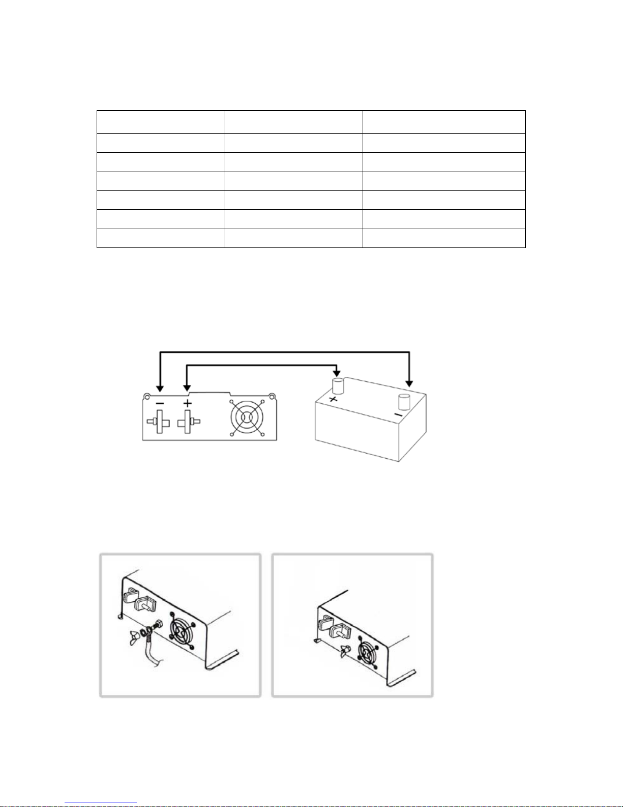
Electrical connection
General instructions for electrical connection.
In case of the inverter is installed into vehicles or boats it has to be
connected to the chassis (ground).
If cables have to be inserted to metal walls or other sharp-edged means,
use a cable duct or cable bushes.
Do not pull the cables.
Do not lay cables loose or in sharp bends on electrical conducting
materials (metal).
Do not lay 110V mains cable and 12/24 VDC cable together into the
same cable duct.
The specified minimum cable cross section must be complied with.
Secure cables properly.
Lay cables in such a way that no tripping is possible.
Lay cables in such a way that no exposure to or risk of damage is
possible.

Cables: Make sure to use the correct cables. A chart is provided below,
for your reference:
Max. Watt Output
DC Amps Req’d
Wire Gauge
150W
15A
#14
300W
30A
#10
600W
60A
#6 or 2 x #10
1000W
100A
#2 or 2 x #6
1500W
150A
#2 or 2 x #6
2200W
220A
#2 or 2 x #6
Connection to the battery
-Lay the flexible connecting cable (positive) and (negative) from the
battery to the connecting terminals of the inverter (take cable cross
section from the table).
-Connect first the positive, then the negative cable.
! Make sure the terminals are not reversed!
Reverse polarity connection will blow the internal fuses. This will void the
warranty.
-Lay the flexible chassis ground cable from the chassis of the vehicle to
the chassis ground on the rack of the inverter.
-Connect the chassis ground.

! Reverse polarity connection of the battery wires can damage the
inverter. Do not use the inverter with electrical systems using positive
ground.
Operation: 600W / 1000W / 1500 / 2200 pure sine wave inverter
Power on:
On the LED control “Power” lighting - Green LED.
Over load:
One the LED control “Over-Load” lighting-Red LED.
Over temperature:
On the LED control “Over-Temp” lighting-Red LED.
Problem
Possible Cause
No output voltage,
LED does not light
1. On/Off switch is not in the power ON
position.
2. Bad contact of the connections
between battery and inverter.
3. Internal fuses blown. In this case, send
the unit back to Power Bright for repair.
No output voltage, OVER-
TEMP LED Lights Red The inverter has been overheated.
Switch off the inverter and the device.
Wait approx. 2 minutes and switch on
the inverter only. Reduce the load and
make sure that there is better ventilation
for the inverter. Then switch on the
inverter and the device again.
Overload LED
Current consumption of the device is too
high. Also there could be a short of the
device. Switch off the inverter and
disconnect the device. Switch on the
inverter again. If the OVERLOAD LED is
off, there is a short circuit in the device or
the total load was higher than the
specified wattage of the inverter. Check
the connecting cable of the consumer for
mechanical damages.
Audible signal in case of
under voltage
Battery voltage too low. In case of the
battery load voltage falls below 11V
resp. 22V. The battery has to be re-
charged.

Specifications:
Model
782-6610
782-6611
Continuous Power
600W
1000W
Surge
1000W
2000W
Output Voltage
115V+/-3%
115V+/-3%
Output Freq.
60Hz
60Hz
Waveform
Pure Sine
Pure Sine
Total
Harmonic
Distortion
< 3%
< 3%
Input Voltage Range
10V-15V
10V-15V
Efficiency
> 85%
> 85%
No Load Current Draw
0.85A
< 1.0 amp
Low Battery Alarm
10.7V
10.7V
Low Battery
Shut-Down 10V
10V
Dimension
(L x W x H)
13.2 x 9.3 x 3.3 in.
16.7 x 9.3 x 3.3 in.
Weight
8 lbs
11 lbs

Specifications:
Model
782-6612
782-6613
Continuous Power
1500W
2200W
20 Minutes
1800W
2500W
Surge
3000W
3600W
Output Voltage
115V+/-3%
115V+/-3%
Output Freq.
60Hz
60Hz
Waveform
Pure Sine
Pure Sine
Total Harmonic Distortion
< 3%
< 3%
Input Voltage Range
10V-15V
10V-15V
Efficiency
> 85%
> 85%
No Load Current Draw
< 1.0 amp
< 1.0 amp
Low Battery Alarm
10.7V
10.7V
Low Battery
Shut-Down
10V
10V
Dimension
(L x W x H) 16.3 x 11.2 x 3.9
16.3 x 11.2 x 3.9
Weight
13.8 lbs
17 lbs

This manual suits for next models
3
Table of contents
Other Fusion Inverter manuals
Popular Inverter manuals by other brands

Kohler
Kohler 12RES Operation and installation instructions

SMA
SMA Sunny Island 6048-US Technical description

Mitsubishi Electric
Mitsubishi Electric PV-PNS03ATL-GER Operation manual

Ozito
Ozito IGP-3300 Assembly & Safety Warnings

Sofar
Sofar ESI 3K-S1 user manual

WELDING INDUSTRIES
WELDING INDUSTRIES 125i MC91-0 Operator's manual