Pioneer PDV-LC20 User manual

ORDER NO.
PIONEER CORPORATION 4-1, Meguro 1-chome, Meguro-ku, Tokyo 153-8654, Japan
PIONEER ELECTRONICS SERVICE, INC. P.O. Box 1760, Long Beach, CA 90801-1760, U.S.A.
PIONEER EUROPE NV Haven 1087, Keetberglaan 1, 9120 Melsele, Belgium
PIONEER ELECTRONICS ASIACENTRE PTE. LTD. 253 Alexandra Road, #04-01, Singapore 159936
PIONEER CORPORATION 2000
c
Model No. Order No. Remarks
PDV-LC20 RRV2401 Confirmation / adjustment of a LCD
monitor part.
Type Model Power Requirement Region No. Remarks
PDV-LC20 PDV-20
ZU/CA – AC120V Adapter or Battery pack 1
ZY AC100V-240V Adapter or Battery pack 2
ZL AC100V-240V Adapter or Battery pack 3
PDV-LC20
RRV2383
T – IZE SEPT. 2000 Printed in Japan
PDV-20
THIS MANUAL IS APPLICABLE TO THE FOLLOWING MODEL(S) AND TYPE(S).
POTABLE DVD PLAYER
1. SAFETY INFORMATION ....................................... 2
2. EXPLODED VIEWS AND PARTS LIST ................. 4
3. BLOCK DIAGRAM AND SCHEMATIC DIAGRAM ... 10
4. PCB CONNECTION DIAGRAM ........................... 30
5. PCB PARTS LIST ................................................ 35
6. ADJUSTMENT..................................................... 39
CONTENTS 7. GENERAL INFORMATION ................................ 40
7.1 DIAGNOSIS .................................................. 40
7.1.1 DISASSEMBLY .................................... 40
7.1.2 TROUBLE SHOOTING ........................ 43
7.2 IC .................................................................. 44
8. PANEL FACILITIES AND SPECIFICATIONS.... 55
COLOR BRIGHT MONITOR
PUSH
CL0SE
MENU
OFF ON
¡ ¢
4 1
87
3
3
2
5
∞
SETUP
RETURN TOP MENU
ENTER
• PDV-LC20
• Battery pack
(PDV-BT20 / PDV-BT25)
(PDV-BT20 is supplied with PDV-LC20)
* These exchange a product in service.
Option
BATTERY PACK
PDV-BT20
PDV-BT25Z/E
Z/E
• This service manual should be used
together with the following manual (s) :

2
PDV-LC20, PDV-20
1. SAFETY INFORMATION
This service manual is intended for qualified service technicians ; it is not meant for the casual do-it-
yourselfer. Qualified technicians have the necessary test equipment and tools, and have been trained
to properly and safely repair complex products such as those covered by this manual.
Improperly performed repairs can adversely affect the safety and reliability of the product and may
void the warranty. If you are not qualified to perform the repair of this product properly and safely, you
should not risk trying to do so and refer the repair to a qualified service technician.
WARNING
This product contains lead in solder and certain electrical parts contain chemicals which are known to the state of California to cause
cancer, birth defects or other reproductive harm. Health & Safety Code Section 25249.6 – Proposition 65
NOTICE
(FOR CANADIAN MODEL ONLY)
Fuse symbols (fast operating fuse) and/or (slow operating fuse) on PCB indicate that replacement parts must
be of identical designation.
REMARQUE
(POUR MODÈLE CANADIEN SEULEMENT)
Les symboles de fusible (fusible de type rapide) et/ou (fusible de type lent) sur CCI indiquent que les pièces
de remplacement doivent avoir la même désignation.
ANY MEASUREMENTS NOT WITHIN THE LIMITS
OUTLINED ABOVE ARE INDICATIVE OF A POTENTIAL
SHOCK HAZARD AND MUST BE CORRECTED BEFORE
RETURNING THE APPLIANCE TO THE CUSTOMER.
2. PRODUCT SAFETY NOTICE
Many electrical and mechanical parts in the appliance
have special safety related characteristics. These are
often not evident from visual inspection nor the protection
afforded by them necessarily can be obtained by using
replacement components rated for voltage, wattage, etc.
Replacement parts which have these special safety
characteristics are identified in this Service Manual.
Electrical components having such features are identified
by marking with a on the schematics and on the parts list
in this Service Manual.
The use of a substitute replacement component which does
not have the same safety characteristics as the PIONEER
recommended replacement one, shown in the parts list in
this Service Manual, may create shock, fire, or other hazards.
Product Safety is continuously under review and new
instructions are issued from time to time. For the latest
information, always consult the current PIONEER Service
Manual. A subscription to, or additional copies of, PIONEER
Service Manual may be obtained at a nominal charge from
PIONEER.
1. SAFETY PRECAUTIONS
The following check should be performed for the
continued protection of the customer and service
technician.
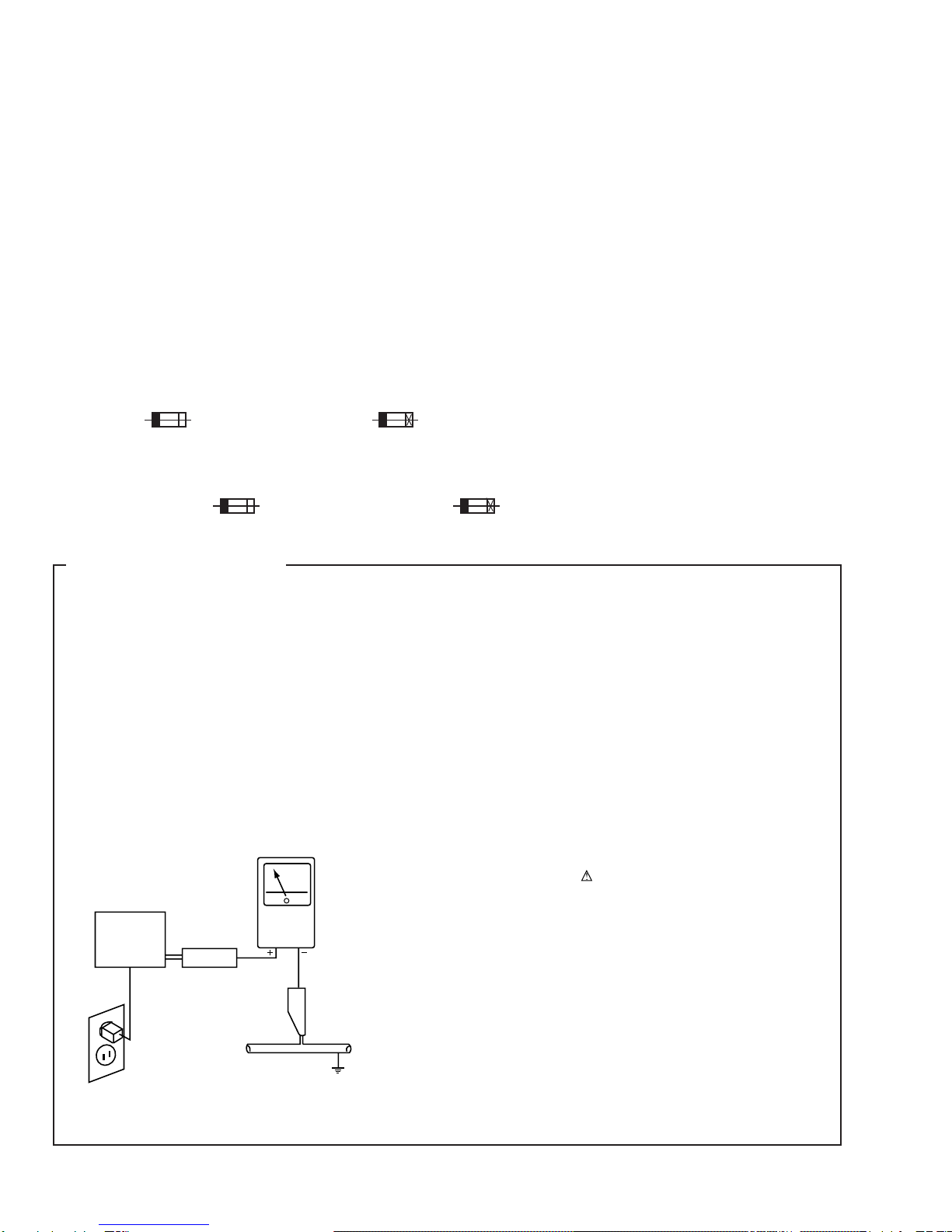
LEAKAGE CURRENT CHECK
Measure leakage current to a known earth ground (water
pipe, conduit, etc.) by connecting a leakage current tester
such as Simpson Model 229-2 or equivalent between the
earth ground and all exposed metal parts of the appliance
(input/output terminals, screwheads, metal overlays, control
shaft, etc.). Plug the AC line cord of the appliance directly
into a 120V AC 60Hz outlet and turn the AC power switch
on. Any current measured must not exceed 0.5mA.
(FOR USA MODEL ONLY)
Leakage
current
tester
Reading should
not be above
0.5mA
Device
under
test
Test all
exposed metal
surfaces
Also test with
plug reversed
(Using AC adapter
plug as required)
Earth
ground
AC Leakage Test

3
PDV-LC20, PDV-20
WARNING!
The AEL(accessible emission level) of the laser power output is less than CLASS 1
but the lasear component is capable of emitting radiation exceeding the limit for
CLASS 1.
A specially instructed person should do servicing operation of the apparatus.
CAUTION
Danger of explosion if battery is incorrectly replaced.
Replaced only with the same or equivalent type
recommended by the manufacture.
Discord used batteries according to the manufacture's
instructions.
LABEL CHECK
ZU/CA Type Only
ZU/CA Type Only
ZY Type Only
ZY and ZL Types Only
VRW1867
VRW1815
VRW1860
VRW-328
CERTIFICATION
THIS PRODUCT COMPLIES WITH DHHS RULES 21CFR, SUBCHAPTER J,
PART 1040 AT DATE OF MANUFACTURE.
This Class B digital apparatus complies with Canadian ICES-003. Cet appareil
numerique de la classe B est comforme a la norme NMB-003 du Canada.
THIS DEVICE COMPLIES WITH PART 15 OF THE FCC RULES.
OPERATION IS SUBJECT TO THE FOLLOWING TWO CONDITIONS :
(1)THIS DEVICE MAY NOT CAUSE HARMFUL INTERFERENCE, AND
(2)THIS DEVICE MUST ACCEPT ANY INTERFERENCE RECEIVED, INCLUDING
INTERFERENCE THAT MAY CAUSE UNDESIRED OPERATION.
LASER RADIATION WHEN OPEN,
AVOID LONG-TERM VIEWING OF
DIRECT LASER RADIATION.
< VRW1815 >
CAUTION
CAUTION :
VORSICHT :
ADVARSEL :
VARNING :
VARO! :
VISIBLE AND INVISIBLE LASER RADIATION WHEN OPEN.
AVOID EXPOSURE TO BEAM.
SICHTBARE UND UNSICHTBARE LASERSTRAHLUNG, WENN
ABDECKUNG GEÖFFNET NICHT DEM STRAHL AUSSETZEN!
SYNLIG OG USYNLIG LASERSTRÅLING VED ÅBNING UNDGÅ
UDSÆTTELSE FOR STRÀLING.
SYNLIG OCH OSYNLIG LASERSTRÅLNING NÄR DENNA DEL ÄR
ÖPPNAD BETRAKTA EJ STRÅLEN.
AVATTAESSA ALTISTUT NÄKYVÄ JA NÄKYMÄTTÖMÄLLE
LASERSATEIL YLLE. ÄLÄ KATSO SÄTEESEN. VRW1860
VRW-328
LASER DIODE CHARACTERISTICS
FOR DVD : MAXIMUM OUTPUT POWER : 3.2 mW
WAVELENGTH : 650 nm
FOR CD : MAXIMUM OUTPUT POWER : 3.3 mW
WAVELENGTH : 780 nm
CAUTION :
LASER RADIATION WHEN OPEN, AVOID LONG-TERM
VIEWING OF DIRECT LASER RADIATION.
CAUTION :
USE OF CONTROLS OR ADJUSTMENTS OR PER-
FORMANCE OF PROCEDURES OTHER THAN THOSE
SPECIFIED HEREIN MAY RESULT IN HAZARDOUS
RADIATION EXPOSURE.
CAUTION :
TO PREVENT RISK OF ELECTRIC SHOCK AND LASER
EXPOSURE, DISCONNECT THE AC ADAPTER OR THE
BATTERY BEFORE REMOVE SCREWS.
Additional Laser Caution
1. Laser Interlock Mechanism
If the switches to detect door-open state (S603, S605: DISC
OPEN DET) are open, the laser interlock mechanism operates
and shuts down the power source (Q100) to the laser diode drive
circuit. The system microcomputer detects this condition and
does not issue the Laser On command.
If Q100 is defective, accompanying a short-circuit between the
emitter and the collector, the system microcomputer judges this
status as the door-open state, and it does not issue the Laser
On command as long as Q611 is not defective, even if S603 and
S605 are open.
Therefore, the laser does not light unless S603 and S605 are
intentionally short-circuited in door-open state.
To light the laser in Test mode, short-circuit S603 and S605.
Hold S603 and S605 in the depressed position from the top, as
they are push switch.
2. NEVER directly look at the objective lens from a short distance
when lighting the laser by short-circuiting S603 and S605 in door-
open state.

4
PDV-LC20, PDV-20
2.1 PACKING
Player
10
20
PDV-20
Only
ZY Type
Only
PDV-20/ZY
Only
PDV-LC20/ZY
Only
PDV-LC20 Only
PDV-LC20/ZU/CA
and
PDV-LC20/ZL
Only
PDV-20/ZL Only
11, 29
30
2
1
3
4
5
6
19
12 13
18
17 28
15
11, 14, 22-27
7
7
89
21
28
15
11, 14, 22-27
7
11, 14
(PDV-LC20/ZU/CA)
11, 29
(PDV-LC20/ZL)
2. EXPLODED VIEWS AND PARTS LIST
NOTES: •Parts marked by "NSP" are generally unavailable because they are not in our Master Spare Parts List.
•The mark found on some component parts indicates the importance of the safety factor of the part.
Therefore, when replacing, be sure to use parts of identical designation.

5
PDV-LC20, PDV-20
(1) PACKING PARTS LIST
Mark No. Description Part No.
1 Tray VHB1069
2 AC Adapter See Contrust table (2)
3 Power Cable See Contrust table (2)
4 AV Cable (L = 1.5m) VDE1066
5 S Video Cable (L = 1.5m) VDE1067
6 Battery Pack See Contrust table (2)
7 Polyethylene Bag B5 VHL1051
8 Remote Control Unit VXX2724
9 Battery Cover VNK4730
10 Top Plate VHC1045
11 Opearating Instructions VRB1258
(English)
12 Packing Case See Contrust table (2)
13 Handle VEE1006
NSP 14 Warranty Card See Contrust table (2)
15 Manual Holder See Contrust table (2)
Mark No. Description Part No.
16 • • • • •
17 Master Carton See Contrust table (2)
18 Mat Plate VHC1048
19 Mirror Mat DHL1050
20 Name Plate Label See Contrust table (2)
21 Optical Cable See Contrust table (2)
22 Operating Instructions (French) See Contrust table (2)
23 Operating Instructions (Italy) See Contrust table (2)
24 Operating Instructions (German)See Contrust table (2)
25 Operating Instructions (Dutch) See Contrust table (2)
26 Operating Instructions See Contrust table (2)
(Swedish)
27 Operating Instructions (Spanish)See Contrust table (2)
28 Polyethylene Bag See Contrust table (2)
(0.03 ×230 ×340)
29 Operating Instructions (Chinese)See Contrust table (2)
30 Middle Plate See Contrust table (2)
(2) CONTRAST TABLE
PDV-LC20/ZU/CA, ZY, ZL, PDV-20/ZY and ZL are constructed the same except for the following :
Mark No. Symbol and Description Part No.
PDV-LC20
/ZU/CA PDV-LC20
/ZY PDV-LC20
/ZL PDV-20
/ZY PDV-20
/ZL Remarks
NSP
2
3
6
12
14
15
17
20
21
22
23
24
25
26
27
28
29
30
AC Adapeter
Power Cable
Battery Pack
Packing Case
Warranty Card
Manual Holder
Master Carton
Name Plate Label
Optical Cable
Operating Instructions (French)
Operating Instructions (Italy)
Operating Instructions (German)
Operating Instructions (Datch)
Operating Instructions (Swedish)
Operating Instructions (Spanish)
Polyethylene Bag (0.03 ×230 ×340)
Operating Instructions (Chinese)
Middle Plate
VWX1228
RDG1034
VEM1028
VHG1987
ARY7045
VHC1074
VHG1986
VRW1859
Not used
Not used
Not used
Not used
Not used
Not used
Not used
Not used
Not used
Not used
VWX1228
ADG1127
VEM1028
VHG1976
ARY7022
VHC1074
VHG1975
VRW1858
VDE1062
VRD1120
VRD1121
VRD1122
VRD1123
VRD1124
VRD1125
Z21-038
Not used
Not used
VWX1229
ADG1127
VEM1028
VHG2018
Not used
VHC1074
VHG2017
VRW1858
Not used
Not used
Not used
Not used
Not used
Not used
Not used
Not used
VRD1126
Not used
VWX1228
ADG1127
Not used
VHG1991
ARY7022
VHC1062
VHG1990
VRW1858
VDE1062
VRD1120
VRD1121
VRD1122
VRD1123
VRD1124
VRD1125
Z21-038
Not used
VHC1076
VWX1229
ADG1127
Not used
VHG2020
Not used
Not used
VHG2019
VRW1858
Not used
Not used
Not used
Not used
Not used
Not used
Not used
Not used
VRD1126
VHC1076

6
PDV-LC20, PDV-20
3.2 MAIN SECTION
19
18
16
17
15
32
PDV-LC20
Only
PDV-LC20
Only
PDV-LC20
Only
PDV-20
Only
Except
ZU/CA
Type
ZU/CA Type
Only
ZY Type
Only
ZU/CA Type
Only
Refer to
"2.3 LCD MONITOR SECTION".
26
28
27
24
24
20 or 21
34 31 (ZU/CA Type)
or
36 (ZY and ZL Types)
23
10 11
22
12
33
35
7
7
7
2
1
4
13
14
25
9
A
B
8
6
24
29
30

7
PDV-LC20, PDV-20
(1) MAIN SECTION PARTS LIST
Mark No. Description Part No. Mark No. Description Part No.
1 PDVDM Assy See Contrust table (2)
2 PDVDS Assy See Contrust table (2)
3 • • • • •
4 Traverse Mechanism Assy VXX2735
5 • • • • •
6 Rear Cover See Contrust table (2)
7 Float Rubber VEB1303
8 Switch Cap See Contrust table (2)
9 Heat Sink VNH1065
10 IR Filter VNK4709
11 LED Lens VNK4710
12 Open Knob VNK4711
13 Stopper Spring VBH1315
14 Connector Cover See Contrust table (2)
15 Caution Label VRW1847
16 Cover Spring VBH1332
17 Body See Contrust table (2)
18 Top Cover See Contrust table (2)
19 Cover Lens See Contrust table (2)
20 Logo Plate See Contrust table (2)
21 Display Lens See Contrust table (2)
22 Leg Rubber VEB1313
23 Screw VBA1062
24 Screw VBA1061
25 Chassis See Contrust table (2)
26 Operation Button A See Contrust table (2)
27 Operation Button B VNK4707
28 Cursol Key See Contrust table (2)
29 Sheet See Contrust table (2)
30 Display LCD Sheet See Contrust table (2)
31 Label See Contrust table (2)
32 65 Label See Contrust table (2)
33 NP Knob See Contrust table (2)
NSP 34 Caution Label (F) See Contrust table (2)
35 Label (Service) See Contrust table (2)
36 Caution Label See Contrust table (2)
(2) CONTRAST TABLE
PDV-LC20/ZU/CA, ZY, ZL, PDV-20/ZY and ZL are constructed the same except for the following :
Mark No. Symbol and Description Part No.
PDV-LC20
/ZU/CA PDV-LC20
/ZY PDV-LC20
/ZL PDV-20
/ZY PDV-20
/ZL Remarks
NSP
1
2
6
8
14
17
18
19
20
21
25
26
28
29
29
30
31
32
33
34
35
36
PDVDM Assy
PDVDS Assy
Rear Cover
Switch Cap
Connector Cover
Body
Top Cover
Cover Lens
Logo Plate
Display Lens
Chassis
Operation Button A
Cursol Key
Sheet L
Sheet S
Display LCD Sheet
Label
65 Label
NP Knob
Caution Label (F)
Label (Service)
Caution Label
VWS1456
VWG2254
VNK4713
VNK4481
VNK4712
VNK4738
VNK4705
VAH1368
VAH1358
Not used
VNK4731
VNK4706
VNK4708
VEC2186
Not used
Not used
VRW1867
ARW7050
Not used
Not used
VRW1815
Not used
VWS1457
VWG2255
VNK4713
VNK4481
VNK4712
VNK4738
VNK4750
VAH1368
VAH1358
Not used
VNK4731
VNK4706
VNK4708
VEC2186
Not used
Not used
Not used
Not used
VNK4719
VRW-328
Not used
VRW1860
VWS1457
VWG2256
VNK4713
VNK4481
VNK4712
VNK4738
VNK4750
VAH1368
VAH1358
Not used
VNK4731
VNK4706
VNK4708
VEC2186
Not used
Not used
Not used
Not used
VNK4719
Not used
Not used
VRW1860
VWS1461
VWG2259
Not used
Not used
VNK4736
VNK4718
VNK4755
VAH1361
Not used
VAH1360
VNK4754
Not used
Not used
Not used
VEC2187
VEC2182
Not used
Not used
VNK4719
VRW-328
Not used
VRW1860
VWS1461
VWG2260
Not used
Not used
VNK4736
VNK4718
VNK4755
VAH1361
Not used
VAH1360
VNK4754
Not used
Not used
Not used
VEC2187
VEC2182
Not used
Not used
VNK4719
Not used
Not used
VRW1860

8
PDV-LC20, PDV-20
3.3 LCD MONITOR SECTION (PDV-LC20 ONLY)
2-1/2
turns Triangle marked
Note for Assembly
17
9
8
1
17
3
17
20
18
10
13
17 17
12
22
2
7
7
5
45
6
14
11
15
16
to B1
to PDVDM Assy
CN401

9
PDV-LC20, PDV-20
(1) LCD MONITOR SECTION PARTS LIST
Mark No. Description Part No.
1 LCD Panel (Service) VXX2737
2 LCD Main (Service) See Contrust table (2)
3 LCD Inverter (Service) VXX2739
4 LCD FFC 6P (Service) VXX2740
5 Connector Assy 2P VKP2257
6 FPC 22P VNP1800
7 Speaker VVY1003
8 LCD Holder VNK4715
9 LCD Locker VNK4717
10 Lock Spring VBH1316
11 Earth Plate VNH1067
12 Mode Button VNK4716
13 Cushion C VEB1323
14 LCD Cover VNK4714
15 Flexible Sheet VEC2084
16 Support Sheet VEC2188
17 Screw VBA1062
18 Free Stopper VXB1002
19 • • • • •
20 Insulation Sheet VEC2168
21 • • • • •
22 Volume Dial (Service) VXX2756
(2) CONTRAST TABLE
PDV-LC20/ZU/CA, ZY and ZL are constructed the same except for the following :
Mark No. Symbol and Description Part No.
PDV-LC20
/ZU/CA PDV-LC20
/ZY PDV-LC20
/ZL Remarks
2 LCD Main (Service) VXX2738 VXX2748 VXX2748

PDV-LC20, PDV-20
10
A
B
C
D
1234
1234
IR601
REMOTE
SENSOR
(50P)
IC608
GM71VS17803CLT-6
16M DRAM
IC901
CY2081SL-638
Clock Generator
IC606
PD6365A
8M Flash ROM
IC604
TC55V1001AF8
1M SRAM
IC802
HY57V161610DTC-8
16M SDRAM
Spindle
Motor
SLED
MOTOR
T_DRV 8
3
54
9
6
7
11 10 48
47
45 46 14
6
1
20
12
13
14
11,12
19,20
OEIC
Pickup
Assy
T_RTN
B1-B4
B1-B4
B1-B4
RFI
RFO AIN
RF
PDRF
F_DRV
26
SLDR_F
27
15
16
31
SLDR_R
F_RTN
T_DRV
T_RTN TDO
TE
FE
PH
BH
SPDO
DSPCLK
(16M)
27M
DSPRF
EFM IN
FDO
SLDO
F_DRV
SLDR_F
SLDR_R
SPDO
F_RTN
+-
CN120
(35P)
M
A
PDVDM ASSY
B
PDVDS ASSY
TRAVERSE
MECHANISM
ASSY
Q110
35 42 57 56 46
32 33 30 31 39
5IC101
LA9701M
RF IC
IC351
BA5929FP
FTS Driver
IC201
LC78652W
Servo DSP
6-9
5
16M
DSPCLK
(16M)
16M
SREQ
ADAI
SD0-SD7
XSACK
IC610
PE5108A
DVD Decoder
BY Chip
IC602
PD3410A
SH1 ASIC
IC2001
PE5191A
µ-Control IC
IC603
TC74VHCT541AFT
3V→5V Level Shift
IC605
TC7WH125FU
5V→3V Level Shift
170
3
ROMXA
ROMXA
112 56
55
DTR1 DTR
Flash
Memory
Download
TXD
RXD
CTS
18 TXD1
DTR
TXD 17
2
118
102
3
RXD1
2CTS1
RXD
CTS 5
6
101
117
3
CDDATA
111
57-60
63-66
23-26,32-48
107
27M
4
27M
197
36/16M
205
IC801
MB86373B
AV-1
AV Decoder
ADDRESS, DATA BUS
91
64 ADAO
ADAI
ADAO
62
V_HOUT
45 Y_HOUT
39 C_HOUT
36
89
54
78,80-84
86,87
1
33/16M
DACCLK
(33/16M) CN601
(7P)
5
7
6
4
IR
CN602
(50P)
CN2001
PDV-20
ONLY
Q851 (2/2)
Q861 (2/2)
Q871 (2/2)
34
42
85
V2001
VAW1059
LCD
KEY SW
PAL, UD/RL, ZOOM,
WIDE, D_MODE,
LOW_PW, LCD_ON
19-25
1-7
: TV SIGNAL ROUTE
(TV)
: RF SIGNAL ROUTE
: V/CB SIGNAL ROUTE
(V/CB)
: Y SIGNAL ROUTE
(Y)
: C SIGNAL ROUTE
(C)
: AUDIO SIGNAL ROUTE
(V/CB)
(Y)
(C)
3. BLOCK DIAGRAM AND SCHEMATIC DIAGRAMA
3.1 BLOCKM DIAGRAM

PDV-LC20, PDV-20
11
A
B
C
D
5678
5678
TFT COLOR MINITOR
F801
Video Filter
IC412
TC7SH08FU
R475
VR401
10k
R491
IC852
TK15402M
Video Amp.
IC408
LM4863MT
HP & SP Amp.
IC853
TK15416M
Video Drive
IC404
PE8001A
DAC IC IC402 (1/2)
NJU7082BV
IC407 (1/2)
NJU7082BV
IC406 (1/2)
NJM2100V
IC403
(2/3)
IC403
(3/3)
IC403
(1/3)
IC403 :
TC74HC4053AFT
ADAI
ADAO
VOUT
VOUTL
L
H
VOUTR
IVIDEO
VREF
RCH
YOUT
COUT
35 8
2
2
2
1
1
1
3
3
42
6
4
2
1
5
14 12
13
15
16
13
2
5
4
1
2
10
9
15
16 18
12
7
PDV-20 ONLY
PDV-LC20
ONLY
PDV-LC20
ONLY
PDV-LC20
ONLY
Q851 (1/2)
Q861 (1/2)
Q871 (1/2)
JA850
VIDEO
IN/OUT
JA401
AUDIO
IN/OUT
OPTICAL
JA402
PHONES 1
JA403
PHONES 2
SPEAKER L SPEAKER R
(24P)
SPL+
SPL-
CN401
438
Y IN
VIDEO
PAL, UD/RL, ZOOM,
WIDE, D_MODE,
LOW_PW, LCD_ON
10-16
B1
B2
4
1
2
38
10-16
B3
1
2
IC854
MM1507XN
L
H
(V/CB)
(Y)
(C)
(V/CB)
(Y)
(C)
(V/CB) (V/CB)
(V)(V)
(V)
(V)
(V)(V)
(V/CB) (V/CB)
(Y)
(C)
(Y)
(C)
(Y)
(C)

PDV-LC20, PDV-20
12
A
B
C
D
1234
1234
PICKUP ASSY
SPINDLE MOTOR ASSY
TRAVERSE MECHANISM ASSY (VXX2658) VIDEO IN/OUT
/S VIDEO OUT
AC ADAPTER
ZU/CA, ZY : VWX1228
ZL : VWX1229
ZU/CA : AC120V
ZY, ZL : AC100-240V
AUDIO IN/OUT
/OPTICAL OUT DC IN
JA850 JA401 JA851
CN120
PDV-LC20
ONLY
ZY, ZL ONLY
ZY, ZL ONLY
3.2 OVERALL WIRING DIAGRAM

PDV-LC20, PDV-20
13
A
B
C
D
5678
5678
LCD PANEL (For SERVICE)
(VXX2737)
LCD MAIN (For SERVICE)
(ZU/CA : VXX2738)
(ZY, ZL : VXX2748)
LCD INVERTER
(For SERVICE)
(VXX2739)
PDVDS ASSY
(PDV-LC20/ZU/CA : VWG2254)
(PDV-LC20/ZY : VWG2255)
(PDV-LC20/ZL : VWG2256)
(PDV-20/ZY : VWG2259)
(PDV-20/ZL : VWG2260)
B
PHONES 1
PHONES 2
BATTERY
DC IN
DOWNLOAD CONNECTOR
CN401
CN602
CN601
CN11
CN2001
JA402
JA403
PDV-LC20
ONLY
PDV-LC20
ONLY
PDV-LC20
ONLY
PDV-20
ONLY
A1/6- A6/6
PDVDM ASSY
(PDV-LC20/ZU/CA : VWS1456)
(PDV-LC20/ZY, ZL : VWS1457)
(PDV-20/ZY, ZL : VWS1461)
A
REMOTE
RECEIVER UNIT
Note :When ordering service parts, be sure to refer to "EXPLODED VIEWS and PARTS LIST" or "PCB PARTS LIST".

PDV-LC20, PDV-20
14
A
B
C
D
1234
1234
Q121
2SC4081
RAB4C390J
RAB4C220J
Q100
2SA1576A
2/6
A
2/6
A
2/6
A
2/6
A
2/6
A
2/6
A
2/6
A
TRAVERSE MECHANISM ASSY
2/6
A
2/6
A
3/6
A
3/6
A
Q106
2SA1576A
2/6
A
Q114
2SC4081
HN1C01FU
HN1C01FU
A1/6
PDVDM ASSY
(PDV-LC20/ZU/CA : VWS1456)
(PDV-LC20/ZY, ZL : VWS1457)
(PDV-20/ZY, ZL : VWS1461)
(DVD)
(DVD)
(CD)
(CD)
(DVD) (DVD)
(F)
(F) (F)
(S) (S)
(S)
(S)
(S)
(T)
(T)
(T)
(F)
(S)
(T)
(F)
(F)
(F)
(T)
(T)
(S)
1
2 4
3.3 PDVDM ASSY (1/6)
1/6
A

PDV-LC20, PDV-20
15
A
B
C
D
5678
5678
3/6
A
2/6
A
2/6
A
2/6
A
2/6
A
2/6
A
4/6
A
3/6
A
2/6
A
Q127
DTC124EUA
HNC01FU HNC01FU
: RF SIGNAL ROUTE
: ROM DATA SIGNAL ROUTE
(CD)
(CD)
(CD)
: FOCUS SERVO LOOP LINE
: TRACKING SERVO LOOP LINE
(F)
(T)
: SLIDER SERVO LOOP LINE
(S)
(F) (F) (T)
(T)
(S) (F)
(T)
(T)
7
5
6
8
10 11
9
1/6
A

PDV-LC20, PDV-20
16
A
B
C
D
1234
1234
A2/6
PDV-LC20
ONLY
PDV-LC20
ONLY
PDV-20
ONLY
ZU/CA ONLY
ZY, ZL ONLY
CN2001
B
REMOTE
RECEIVER
UNIT
1/6
A
5/6
A
6/6
A
5/6
A
5/6
A
5/6
A
PD6365A
PDVDM ASSY
(PDV-LC20/ZU/CA : VWS1456)
(PDV-LC20/ZY, ZL : VWS1457)
(PDV-20/ZY, ZL : VWS1461)
3.4 PDVDM ASSY (2/6)
2/6
A

PDV-LC20, PDV-20
17
A
B
C
D
5678
5678
ZY, ZL
ONLY
3/6
A
5/6
A
5/6
A
1/6
A
4/6
A
5/6
A
4/6
A
4/6
A
20MHz
1/6
A
1/6
A
1/6
A
1/6
A
1/6
A
1/6
A
1/6
A
1/6
A
1/6
A
3/6
A
3/6
A
5/6
A
RAB4C103J
2/6
A

PDV-LC20, PDV-20
18
A
B
C
D
1234
1234
A3/6
2/6
A
PDVDM ASSY
(PDV-LC20/ZU/CA : VWS1456)
(PDV-LC20/ZY, ZL : VWS1457)
(PDV-20/ZY, ZL : VWS1461)
3.5 PDVDM ASSY (3/6)
3/6
A

PDV-LC20, PDV-20
19
A
B
C
D
5678
5678
4/6
A
4/6
A
1/6
A
4/6
A
5/6
A
1/6
A
2/6
A
5/6
A
1/6
A
1/6
A
: RF SIGNAL ROUTE
: ROM DATA SIGNAL ROUTE
(DVD)(DVD)
(CD) (CD)
3
3/6
A

PDV-LC20, PDV-20
20
A
B
C
D
1234
1234
A4/6
2/6
A
2/6
A
5/6
A
3/6
A
PDVDM ASSY
(PDV-LC20/ZU/CA : VWS1456)
(PDV-LC20/ZY, ZL : VWS1457)
(PDV-20/ZY, ZL : VWS1461)
(C)
(C) (Y) (V/CB)
(C) (Y) (V/CB)
(Y)
(V/CB)
1714 1512
1613
3.6 PDVDM ASSY (4/6)
4/6
A
This manual suits for next models
8
Table of contents
Other Pioneer Portable DVD Player manuals