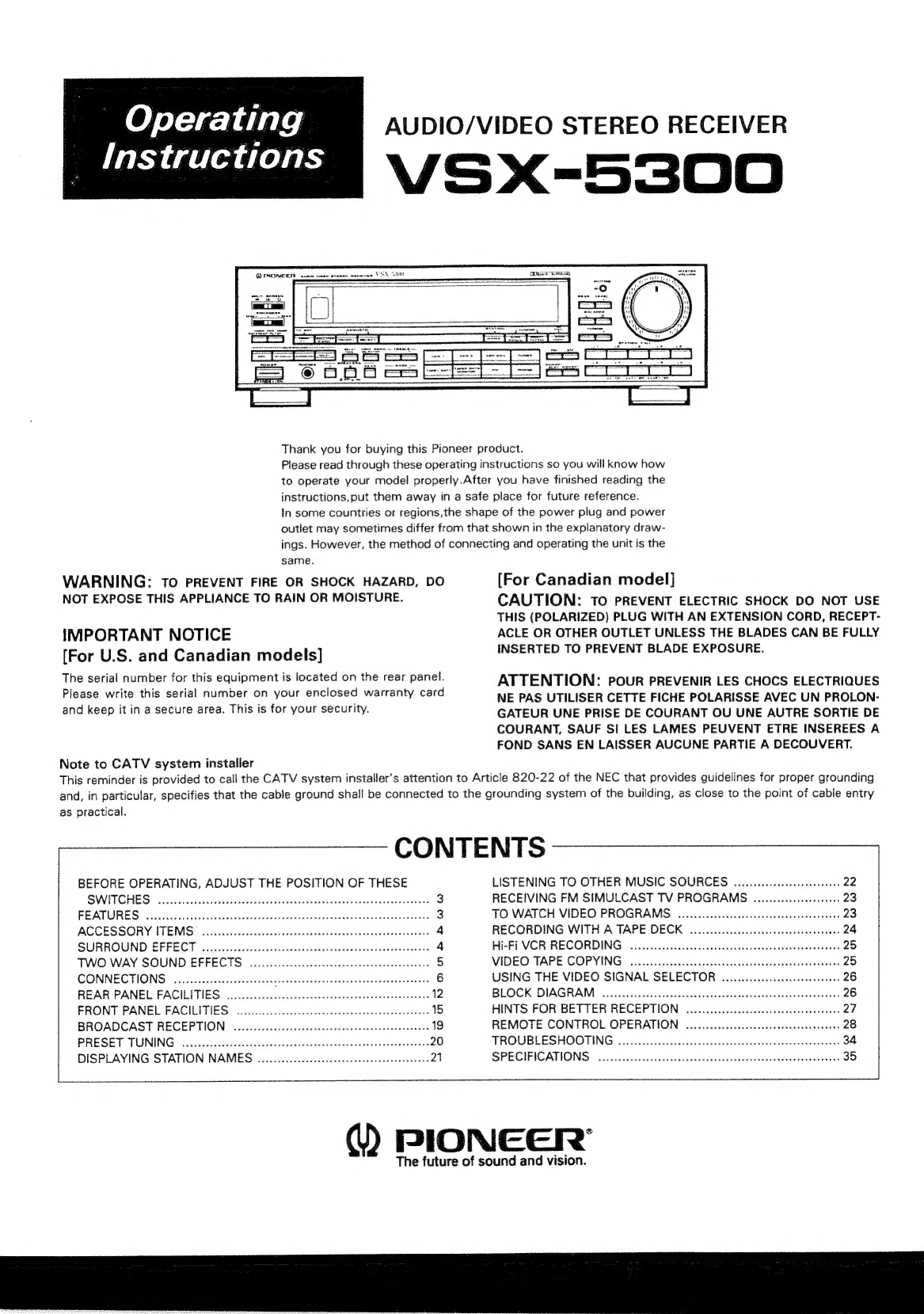
manuals.online logo
Brands
  1. Home
  2. •
  3. Brands
  4. •
  5. Pioneer
  6. •
  7. Stereo Receiver
  8. •
  9. Pioneer VSX-5300 User manual

Pioneer VSX-5300 User manual

AUDIO/VIDEO
STEREO
RECEIVER
VSX-5300
-
Operating
Instructions
C2
PHONEER
ume
wren
erenee
oe
Thank
you
for
buying
this
Pioneer
product.
Please
read
through
these
operating
instructions
so
you
will
know
how
to
operate
your
model
properly.After
you
have
finished
reading
the
instructions,put
them
away
in
a
safe
place
for
future
reference.
In
some
countries
or
regions,the
shape
of
the
power
plug
and
power
outlet
may
sometimes
differ
from
that
shown
in
the
explanatory
draw-
ings.
However,
the
method
of
connecting
and
operating
the
unit
is
the
same.
WARNING:
TO
PREVENT
FIRE
OR
SHOCK
HAZARD,
DO
NOT
EXPOSE
THIS
APPLIANCE
TO
RAIN
OR
MOISTURE.
[For
Canadian
model]
CAUTION:
To
PREVENT
ELECTRIC
SHOCK
DO
NOT
USE
THIS
(POLARIZED)
PLUG
WITH
AN
EXTENSION
CORD,
RECEPT-
ACLE
OR
OTHER
OUTLET
UNLESS
THE
BLADES
CAN
BE
FULLY
IMPORTANT
NOTICE
INSERTED
TO
PREVENT
BLADE
EXPOSURE.
[For
U.S.
and
Canadian
models]
The
serial
number
for
this
equipment
is
located
on
the
rear
panel.
Please
write
this
serial
number
on
your
enclosed
warranty
card
and
keep
it
in
a
secure
area.
This
is
for
your
security.
ATTENTION:
pour
PREVENIR
LES
CHOCS
ELECTRIQUES
NE
PAS
UTILISER
CETTE
FICHE
POLARISSE
AVEC
UN
PROLON-
GATEUR
UNE
PRISE
DE
COURANT
OU
UNE
AUTRE
SORTIE
DE
COURANT,
SAUF
SI
LES
LAMES
PEUVENT
ETRE
INSEREES
A
FOND
SANS
EN
LAISSER
AUCUNE
PARTIE
A
DECOUVERT.
Note
to
CATV
system
installer
This
reminder
is
provided
to
call
the
CATV
system
installer’s
attention
to
Article
820-22
of
the
NEC
that
provides
guidelines
for
proper
grounding
and,
in
particular,
specifies
that
the
cable
ground
shall
be
connected
to
the
grounding
system
of
the
building,
as
close
to
the
point
of
cable
entry
as
practical.
CONTENTS
BEFORE
OPERATING,
ADJUST
THE
POSITION
OF
THESE
LISTENING
TO
OTHER
MUSIC
SOURCES
.......
cece
ceeeeeee
22
SWITCHES
wivckauts
ccasccvandanessonsa
ned
ves
sat
aveeei
sraddeseseereriervantes
3
RECEIVING
FM
SIMULCAST
TV
PROGRAMS
............:00s0e000e
23
FEATURES
3
TO
WATCH
VIDEO
PROGRAMS.
uu...
occ
ceceees
eee
eeneeeeereeee
23
ACCESSORY
ITEMS
©
aeeccccccscscnusvchsclecbdaseaeteasscdeossaxawessacnncee
4
RECORDING
WITH
A
TAPE
DECK
ou...
eee
eeeeceeceeeeeeeeeeeeeeenens
24
SURROUND-EFFECT.
cccicecsacessstedusoscceesyones
stenetseavedsnuweseheave
4
Hi-Fi
VCR
RECORDING
00...
eee
eceeeeeceeeeereceeeuneeeeeaeaeeenens
25
TWO
WAY
SOUND
EFFECTS
5
VIDEO
TAPE
COPYING,
ca
cesssdccaiees
cainaesiscvedsoecaseunes’
cessvesdene
25
CONNECTIONS...
ccceccceeeeceeetetteeeereneneeeeettieeeetetenerentaaees
USING
THE
VIDEO
SIGNAL
SELECTOR
00000...
cece
eee
eeee
26
REAR
PANEL
FACILITIES
BLOCK
DIAGRAM)
sccccveestnictleccesassagsesctbbusaccnchctvineranesescesees
26
FRONT
PANEL
FACILITIES
...
HINTS
FOR
BETTER
RECEPTION
uo...
ceeeeeeeeeeeeecere
nero
eeeee
es
27
BROADCAST
RECEPTION
REMOTE
CONTROL
OPERATION
....00.....
cc
eeeeeeeeeeeeeneeeeeenseees
28
PRESET
TUNING
..........cceceeeteeeceeseceenserareecnsreesseessescesensenee
20
TROUBLESHOOTING...
:2ets
ucicoe
eta
liee
ite
aed
crseten
34
DISPLAYING
STATION
NAMES
...........cccccc
cece
cece
cee
eeeen
ee
neeeees
21
SPEGIFICATIIONS,
<c.c.0fc.eec
hast
desc
ec.
ceva
sosnasneetuaboteatavectusecs
sees
35
PIONGCER'
The
future
of
sound
and
vision.
IMPORTANT
The
lightning
flash
with
arrowhead,
within
an
equi-
Jateral
triangle,
is
intended
to
alert
the
user
of
the
presence
of
uninsulated
‘dangerous
voltage’
within
the
praduct’s
enclosure
that
may
be
of
sufficient
magnitude
to
constitute
a
risk
of
electric
shock
to
persons.
CAUTION
RISK
OF
ELECTRIC
SHOCK
[olom
(ok
me)
13.)
‘
CAUTION:
TO
PREVENT
THE
RISK
OF
ELECTRIC
SHOCK,
DO
NOT
REMOVE
COVER
(OR
BACK).
NO
USER-SERVICEABLE
PARTS
INSIDE.
REFER
SERVICING
TO
QUALIFIED
SERVICE
PERSONNEL.
The
exclamation
point
within
an
equilateral
triangle
is
intended
to
alert
the
user
of
the
presence
of
important
operating
and
maintenance
(servicing)
instructions
in
the
literature
accompanying
the
appliance.
SAFETY
INSTRUCTIONS
READ
INSTRUCTIONS
—
Ali
the
safety
and
operating
instructions
shouid
be
read
before
the
appliance
is
operated.
RETAIN
INSTRUCTIONS
—
The
operating
instruc-
tions
should
be
retained
for
future
reference.
HEED
WARNING
—
All
warnings
on
the
appliance
and
in
the
operating
instructions
should
be
adhered
to.
FOLLOW
INSTRUCTIONS
—
All
operating
and
use
instructions
should
be
followed.
WATER
AND
MOISTURE
—
The
appliance
should
not
be
used
near
water
—
for
example,
near
a
bathtub,
washbow/i,
kitchen
sink,
laundry
tub,
ina
wet
basement,
or
near
a
swimming
pool,
etc
LOCATION
—
The
appliance
should
be
installed
in
a
stable
location.
WALL
OR
CEILING
MOUNTING
—
The
appliance
should
not
be
mounted
to
a
wall
or
ceiling.
POWER
LINES
—
An
outdoor
antenna
should
be
located
away
from
power
lines.
NONUSE
PERIODS
—The
power
cord
of
the
appliance
should
be
unplugged
from
the
outlet
when
left
unused
for
a
long
period
of
time.
OBJECT
AND
LIQUID
ENTRY
—
Care
should
be
taken
so
that
objects
do
not
fall
and
liquids
are
not
spilled
into
the
enclosure
through
openings.
DAMAGE
REQUIRING
SERVICE
—
The
appliance
should
be
serviced
by
a
Pioneer
authorized
ser-
vice
center
or
qualified
service
personnel
when
@
The
power-supply
cord
or
the
plug
has
been
damaged;
or
@
Objects
have
fallen,
or
liquid
has
been
spilled
into
the
appliance;
or
@
The
appliance
has
been
exposed
to
rain;
or
@
The
appliance
does
not
appear
to
operate
nor-
mally
or
exhibits
a
marked
change
in
perfor-
VENTILATION
—
The
appliance should
be
situated
mance;
or
so
that
its
location
or
position
does
not
interfere
@
~The
appliance
has
been
dropped;
or
the
enclosure
with
its
proper
ventilation.
For
example,
the
ap-
damaged
pliance
should
not
be
situated
on
a
bed,
sofa,
rug,
or
similar
surface
that
may
block
the
ventilation
openings:
or,
placed
in
a
built-in
installation,
such
as
a
bookcase
or
cabinet
that
may
impede
the
flow
of
air
through
the
ventilation
openings
HEAT
--
The
appliance
should
be
situated
away
from
heat
sources
such
as
radiators,
heat
registers,
stoves,
or
other
appliances
(including
amplifiers)
that
produce
heat
POWER
SOURCES
—
The
appliance
should
be
connected
to
a
power
supply
only
of
the
type
described
in
the
operating
instructions
or
as
marked
on
the
appliance.
POWER-CORD
PROTECTION
~—
Power-supply
cords
should
be
routed
so
that
they
are
not
likely
to
be
walked
on
or
pinched
by
items
placed
upon
or
against
them,
paying
particular
attention
to
cords
at
plugs,
convenience
receptacles,
and
the
point
where
they
exit
from
the
appliance
POLARIZATION
--
If
your
purchased
product
is
provided
with
a
polarized
power
pluy,
please
read
the
following
instructions.
This
product
is
equipped
with
a
polarized
alternating
current
line
plug
(a
plug
having
one
blade
wider
than
the
other).
This
phag
will
fit
into
the
power
outlet
only
SERVICING
—
The
user
should
not
attempt
to
service
the
appliance
beyond
that
described
in
the
Operating
instructions.
For
all
other
servicing,
contact
the
nearest
Pioneer
authorized
service
center
POWER
LINES
SERVICE
o
ENTRANCE
CONDUCTORS,
ee
GROUND
GROUND
WIRE
ab
OUTDOOR
ANTENNA
GROUNDING
—
If
an
out-
side
antenna
is
connected
to
the
antenna
termi-
nal,
be
sure
the
antenna
system
is
grounded
so
as
to
provide
some
protection
against
voltage
surges
and
built
up
static
charges
In
the
U.S.A.
section
810
of
the
National
Elec-
trical
Code,
ANSI/NFPA
No.
70-1984,
pravides
information
with
respect
to
proper
grounding
of
the
mast
and
supporting
structure,
grounding
of
the
lead-in
wire
to
an
antenna
discharge
unit,
size
of
grounding
conductors,
location
of
antenna-
discharge
unit,
connection
to
grounding
elec-
trodes,
and
requirements
for
the
grounding
elec-
trode.
See
Fig.
A
a)
Use
No.
10
AWG
(5.3
mm?)
cop-
per,
No.
8
AWG
(84
mm?)
alu-
minum,
No.
17
AWG
(1.0
mm?)
copperclad
steel,
bronze
wire,
or
larger
as
ground
wire
b)
Secure
antenna
lead-in
and
ground
wires
to
house
with
stand-off
insulators
spaced
from
4
feet
(1.22
meters)
to
6
feet
(1.83
meters)
apart
c)
Mount
antenna
discharge
unit
as
closely
as
possible
to
where
lead-
in
enters
house
STAND.
OFF
d)
Use
jumper
wire
not
smaller
than
INSUEATORS
2
No6
AWG
(13.3
mm?)
copper,
or
the
equivalent,
when
a
sepa-
rate
antenna-
grounding
electrode
is
used.
See
NEC
Section
810-21
(j)
ANTENNA
LEAD
IN
WIRE
TO
EXTERNAL
ANTENNA
TERMINALS
OF
PRODUCT
ANTENNA
Weas
awelj
“yourees
oui
pue
one
way
This
tsa
safety
feature.
If
you
are
unable
SERVICE
ENTRANCE
DISCHARGE
UNIT
&
to
insert
the
plug
fully
into
the
outlet,
try
reversing
EQUIPMENT
GROUND
the
plug.
df
the
plug
should
sull
fail
to
fit,
contact
WIRE
ab
your
electrician
to
replace
your
obsolete
autlet
Do
not
defeat
the
satety
purpose
of
the
polarized
GROUND
plug
POWER
SERVICE
oe
CLAMES
CLEANING
The
appliance
should
be
cleaned
only
GROUNDING
ELECTRODE
SYSTEM
with
a
polishing
cloth
or
a
soft
dry
cloth.
Never
(eg
intenor
metal
water
ppe)
Clean
with
furniture
wax,
benzine,
insecticides
or
BONDING
Hy
ORIVEN
8
FEET
(2
44
m)
3
3
enit
es
‘s
"
r
:
+
INTO
THE
EARTH
other
volatile
tquids
since
they
may
corrode
the
JUMPER
&
re
ie
REQUIRED
BY
cabinet
FIG.A
u
LOCAL
CONES
SEE
U
NEC
SECTION
810
21
(1)
(7
OPTIONAL
ANTENNA
GROUNDING
ELECTRODE
2
~CARB1113
>
‘A284
(WVHOOUd)
WOd
‘suofoniisut
Buneiedo
ayy
wos
uoneuesdxe
yxau
ay}
alajap
aseaig
»NOLLVYAdO
dGA,,
YONDaS
:1¢
aBeg
e
BEFORE
OPERATING,
ADJUST
SWITCHES
TWO
VOLTAGE
SELECTOR
SWITCHES
Only
multi-voltage
models
are
provided
with
these
switches.
U.S.,
Canadian,
European,
U.K.,
and
Australian
models
are
not
provided
with
these
switches.
The
line
voltage
selector
switches
are
on
the
rear
panel.
Before
your
model
is
shipped
from
the
factory,
these
switches
are
set
to
the
power
requirements
of
the
destination.
Check
that
they
are
set
properly
be-
fore
plugging
the
power
cord
into
the
household
wall
socket.
If
the
volt-
age
is
not
properly
set
or
if
you
move
to
an
area
where
the
voltage
requirements
differ,
adjust
the
selector
switches
as
follows.
*
e
e
e e
ac]
a]
°
u
oe
3¢°
&
OW
Sone
=
>»
30
Ad
D
@
sg
727
©
ao
Foe
a
®
oa
2s
oO
®
Sos
©
wo
=
Ww
ogo
8
®
=
a
o
2
=
®@,r
Pps
=
32
%S8
@®--FS
@
2027
&
2
;
2
be
>
8
bn
(53
wn
ow
5x
27D
w
7
om
of
3
w&
Bi
oY
@
13)
‘om
}
o
>
m
2O5
a
a
a
©
©
23
of825
8)
65
8
oF2
8
SAS
eS
erases
fle
38s
gj
g
oO
a>
on
Oo
°
22
y
3
*
3
¢B8cme
>
>
3
325
3
2?
(Gs
:
.
—
=
.
s
AO
gD
<
3
Ce
een
s
m
3
o
ff.
:
fe
BR
gf
g8342
9)
8
©
888
6
toe
foe]
0
egr?
(e)
‘v
bo
Sa
{
~
>
ser,
om
m
$2402
im
212:
Pe
eS
IG
<
>rszuS
OO
i
ro)
asst
]
3
oh
m
Seeee
a
oe
83
m
e
Reyes
a
th
4
Bs)
O
FseBs
3
1
O
a
9
Eaau
4
x
S27
76
ns
4
Be
>
zeke.»
$San4
6
=
a°%
2
sece@ctj_
mM
O
FAFGuow
Mm
!
0
=a
i?)
Pes
GS
om
#728
8/72
3
&
ge
:
—
Fo]
-
e
8
y
oO
z
eod
gf
+
m
=
®
ae
fey
2
g
>
58
Ee
L
9
2
rc
ig
a
20a
—pn
>
-
m
'
9
G§
2238
Z
®
BQ
‘Uv
2
>
=
2
a
o
=|
m
sa
25
i
x
3
3
=@
Gq)
n
jo)
b
See
3
=)
a
i
5
328
-
8
ra}
GON
®
a
OD
a
=
2
2428
>
8
:
78
8
&
=
aos
5
Qs
a
e
ry
° °
e
“2
7
ye
tome
cd
o
ega58
Bg
3
Z
O85
BU
go
3
2
-
°
3
2
(Te
—
Seng
n
32>
a:
+5528
oma
@~
¢&
a
Z
f
g@~
S08
i:
2"
3
—
7O5a
Lr
~~
=
2.
a
a®@>5
oa
cake
es
2728,
i
ee8
2a
©
o°
8
2@
(On
c
=
2
as
Cc
su
6
Fe
8
”
eagm2
5
32
=~
=
=
»
2
®
'
~
o
3
...
z
o
®.
nn
=
exrt
5
aSe
ae
D
gee
g@
uv
=
an
=
a55
08
°
345
B83
I
og
us
Sey
g
eae
~
PEE
gee?
S4e5o8
@
es
gibi
ne
Sega
ro
3
e
eee
Ce
o
=
an
1
on
g
6
Ese
?
252%
ie)
Cae
ge
Oe
a
Oe
t
5
=
£8
:o
3g.
a
=
Bi
cos
3
t
®
ee
6
7208
Lm
3
8
a
aon
c
SS
a
S532
s
Cc
wn
e290
3
aa
=
®
anaes
x
a
oN
i)
=
oD
a
>
»
aw
¥
=
ze
<
Beas
&
i
THE
POSITION
OF
THESE
CHANNEL
STEP/FM
DE-EMPHASIS
SWITCH
The
unit
has
been
factory
preset
to
the
channel
allocation
and
de-
emphasis
value
for
the
area
in
which
it
is
to
be
sold.
If
these
values
are
set
incorrectly,
the
frequency
display
may
stop
at
the
wrong
frequen-
cy,
or
sound
may
be
distorted,
resulting
in
an
inability
to
reproduce
reception
signals
at
their
proper
sound
quality.
For
this
reason,
be
sure
to
confirm
that
the
values
are
set
correctly
before
first
using
the
unit.
[100kHz/10kHz/75,s]
position:
Set
to
this
position
for
areas
with
an
FM
reception
step
of
100kHz,AM
10kHz,
and
de-emphasis
75s.
{SOkH2/9kHz/50xns]
position:
1,
for
areas
with
an
FM
reception
step
of
50kHz,
AM
dhasis
50ps.
ut
the
channel
allocation
and
de-emphasis
values
for
t
your
dealer
for
correct
information.
LECTORS
AC
240V
1VOOkHz
EM
7
7555
NOILDSYHOO
Q9kHz——AM
—1OkHz
240V
7
CHANNEL
STEP
/FM
DE-EMPHASIS
MEMORY
FUNCTION
:)
of
tone
control
settings
can
be
preset.The
settings
d
flat
tone
response
functions
can
also
be
selected
ALL-LETTER
DISPLAY
FUNCTION
of
broadcast
stations
can
be
preset
(up
to
four
be
set
to
show
either
the
broadcasting
frequency
or
or
example,
WBAC).
The
four-character
display
can
al-
to
display
your
name,
or
the
type
of
material
broad-
dle,
JAZZ,
NEWS,
etc)
»te
Control
Unit
:d
remote
control
unit
you
can
operate
any
Pioneer
audio
nent
bearing
the
fi}
mark.
(LO3YHOD)
ene
le
(LOSHYOONI)
zz
OOES-XSA
3
<ARB1113>
ACCESSORY
ITEMS
see
FM
T-type
Antenna
AM
Loop
Antenna
Remote
control
unit
Dry
cell
battery
SURROUND
EFFECT
This
unit
has
a
built-in
surround
processor
for
adding
presence
and
an
Surround
Speaker
Installation
Examples
expansive
effect
to
the
sound.
To
get
the
most
out
of
the
surround
system,
place
the
speakers
as
STADIUM:
shown
below.
Select
this
position
when
watching
sports
programs
such
as
baseball
games
etc.,
for
a
stadium-like
effect.
SIMULATED
SURROUND:
Example
of
center
speaker
configration
Use
this
mode
for
monaural
sources.
You
will
obtain
an
expansive
sound,
with
outstanding
presence.
DOLBY
SURROUND
Choose
this
setting
for
movies
(especially
video
tapes
bearing
the
O1O/
DOLBY
SURROUND
|
mark)
and
music
playback.
You
will
enjoy
an
effect
similar
to
that
of
movie
theaters
or
concert
halls.
When
using
DOLBY
SURROUND,
a
delay
time
setting
of
20ms
is
usually
about
right.
If
your
rear
speakers
are
very
close
to
the
listening
posi-
tion,
try
30ms;
if
they
are
some
distance
away,
15ms.
CENTER
SPEAKER
FRONT
YW)
SURROUND
Lert
EY)
rich,
Manufactured
under
license
from
Dolby
Laboratories
Licensing
Cor-
poration.
Additionally
licensed
under
one
or
more
of
the
follow-
ing
patents:
U.S.
numbers
3,632,886,
3,746,792
and
3,959,590:
CANADA
numbers
1,004,603
and
1,037,877.
‘‘Dolby’’
and
the
double-D
symbol
are
trademarks
of
Dolby
Laboratories
Licensing
Corporation.
Manufacturé
sous
licence
de
Dolby
Laboratories
Licensing
Corpo-
ration.
En
outre,
sous
license
d‘un
ou
plusiers
des
brevets
suivants:
numéros
américains
3,632,886,
3,746,792
et
3,959,590;
numéros
canadiens
1,004,603
et
1,037,877.
Le
terme
“Dolby”
et
le
symbole
Double-D
sont
des
marques
déposées
de
Dolby
Laboratories
Licensing
Corporation.
4
~<ARB1113
>
[Example
A:]
Sound
appears
to
come
from
directly
in
front
of
the
listener.
Good
for
listening
to
music
recordings.
{Example
B:]
Offers
most
varied
effects;
good
for
watching
sports
programs
or
listen-
ing
to
live
recordings.
{Example
C:]
Good
sound
dispersion;
recommended
for
movies,
etc.
Example
A:
Example
B:
SURROUND
EFFECT
EFFECT
CHART
Example
SURROUND
‘
SIMULATED
STADIUM
x
DOLBY
x
Example
C:
CLEFT
(Ww)
RIGHT
TV
RIGHT
LEFT]
{|
TV
|
[RIGHT]
F
sss
MM
Listening
area
TWO
WAY
SOUND
EFFECTS
SURROUND
Listening
area
C
SURROUND
LEFT
IGHT.
VCR
NOISE
FILTER
When
playing
back
a
monaural
VCR,
there
is
a
tendency
for
audible
high-
frequency
hiss
to
be
produced.
When
playing
back
video
tapes,
if
the
audio
channels
contain
noticeable
high-frequency
tape
hiss,
pressing
this
switch
will
improve
the
sound.
SIMULATED
STEREO
This
function
transforms
monaural
signals
into
simulated
stereo
sound.
Use
it
when
you
wish
to
experience
a
sense
of
stereo
presence
when
listening
to
AM
broadcasts,
or
VCR
and
other
monaural
signal
sources.
NOTE:
The
simulated
stereo
function
can
also
be
used
with
stereo
sound
sources,
but
it
will
result
in
an
effect
somewhat
different
from
the
normal
stereo
sound.
5
<ARB1113>
CONNECTIONS
BASIC
AUDIO
SYSTEM
CONNECTIONS
|
Power
cord
connection
Accessory
FM-T
type
antenna
Accessory
AM
Loop
antenna
Receiver
oO
@®
oO
®
Cassette
tape
|
deck
1/DAT
1
Wall
(0)
socket
CD
player
Speaker
system
IMPEDANCE
SELECTOR
Set
to
match
the
impedance
Speaker
cord
connection
(1)
Push
the
knob.
(2)
Insert
the
cord.
(3)
(3)
Pull
the
knob.
of
the
speakers
being
used.
(See
page
13.)
>
aa
acln
Turntable
6
<ARBING
>
BASIC
VIDEO
SYSTEM
CONNECTIONS
VHF
antenna
CONNECTIONS
ss
=
a
UHF
antenna
Normal
TV
i
a
@
—
TeNna|
oll
Receiver
ala
aFz
=
@
Aveta
RF
modulator
JA-RF5
(Sold
separately)
LD
player,
CDV
player,
etc.
(VHF OUT)
ANT
(VHF
IN)
3
<ARB1113>
CONNECTIONS
arenes
enn
rena
SURROUND
SPEAKER
CONNECTIONS
Receiver
AG
OUTLETS
SWITCHED
UNSWITCHED
TOTAL
100W
Max
200W
MAK
<1
Monaural
amplifier
Right
Channel
Center
Channel
Left
Channel
Right
Channel
AC
wall
socket
8
~ARBIN3
>
CONNECTIONS
When
used
with
another
amp
(power
amplifier,
preamplifier).
(a)
When
using
the
preamplifier
of
the
receiver
and
using
a
separate
stereo
power
amplifier
to
increase
power.
{b)
When
using
the
power
amplifier
of
the
receiver
and
using
a
separate
stereo
preamplifier.
(a)
Amplifier
Speaker
system
Remove
both
|
connector
bar
AC
wall
socket
Stereo
pre-amplifier
9
<ARB1113>
CONNECTIONS
Application
example
—
MULTI-AMPLIFIER
SYSTEM
Crossover
Network
High
range
Low
range
PRE
AMP
POWER
AMP
OUT
IN
|
+
|
\
Receiver
PRE
AMP
POWER
AMP
Precaution
regarding
installation
position
of
cassette
tape
deck.
If
the
cassette
tape
deck
is
installed
in
the
‘‘NO
GOOD"
positions
shown
in
the
drawing
below,
hum
may
occur
during
playback.
NO
GOOD
NO
GOOD
a
GOOD
=
ec
=
NO
GOOD
i
10
SARBIN3
>
Power
Amplifier
Tweeter
Woofer
Tweeter
Ie
ara
Speaker
system
CONNECTIONS
eee
APPLICATIONS
Cassette
tape
deck
2/DAT
2
Cassette
tape
deck
2/DAT
Graphic
equalizer
>
Ree
REC
mt
1H
oo
TV
monitor
2
TV
monitor
1
11
<ARB1113>
REAR
PANEL
FACILITIES
eS
%)
iy
B)
©)
@)
&)
3
(©)
(=)
{=
5
a”
©
3
ale
©
0
=
Z,
AMP
Outi
Am
|
“IN
auc
[
3m,
A
Se
a)
a
@
®
®
20)
12
*[ARBI1113
=
REAR
PANEL
FACILITIES
(1)
FM/AM
ANTENNA
terminals
Use
these
antenna
terminals
for
reception
of
normal
FM
and
AM
broadcasts.
(2)
STATION
PRESET/STATION
NAME
switch
Determines
the
number
of
presets
possible
using
the
STATION
CALL
switches.
10:
You
can
store
a
name
for
each
station
at
this
position,
but
each
STATION
CALL
switch
can
store
one
station
(10
station
total).
30:
Each
STATION
CALL
switch
can
store
three
stations
(30
stations
total).
(Press
once,
twice,
or
three
times
to
select.)
(3)
GND
terminal
Connect
the
turntable
ground
lead
to
this
terminal.
(4)
SURROUND
BALANCE
control
Use
to
adjust
the
surround
effect
from
the
surround
speakers.
Normally
leave
in
the
center
position.
When
inputting
a
monaural
signal,
adjust
so
that
the
surround
output
is
minimum.
(5)
CENTER
OUT
jack
This
is
the
Dolby
surround
center
channel
signal
output
jack.It
can
also
be
used
as
a
3D
system
MONO
output.
(6)
REAR
SPEAKERS
terminals
Connect
the
surround
speakers
to
these
terminals.
NOTE:
Do
not
allow
any
of
the
cord’s
conductors
to
protrude
from
the
termi-
nals
or
touch
any
other
conductors.
Malfunctioning
or
breakdowns
may
occur
when
conductors
come
into
contact
with
each
other.
Use
surround
speakers
of
impedance
8Q
—
16.
(7)
REMOTE
CONTROL
IN/OUT
jacks
IN:
Connect
this
jack
to
other
Pioneer
components
(main
unit
or
remote
control
unit)
when
using
those
components
to
control
this
unit.
OUT:
Connect
this
jack
to
other
Pioneer
components
when
using
the
remote
control
of
this
units
to
control
the
other
components.
NOTE:
The
receiver's
remote
sensor
does
not
function
when
a
plug
is
inserted
in
the
IN
jack.
To
operate,
point
the
remote
control
unit
at
the
remote
sensor
on
the
component
to
which
the
receiver's
IN
jack
is
connected.
To
the
CONTROL
IN
jack
of
other
component.
Receiver
Pioneer
component
bearing
the
fig}
mark.
Remote
control
unit
(@)
VIDEO
OUT
jacks
Use
to
connect
a
TV
set
for
watching
program
materials
from
a
VCR
or
VDP/CDV
connected
to
this
unit.
[TO
MONITOR
TV
jacks]
Connect
to
monitor
TV
or
to
TV
sets
with
video
input
terminals.
[TO
RF
MODULATOR
jack]
Use
to
connect
a
normal
TV
set.
When
performing
connections,
the
RF
MODULATOR
JA-RF5
(sold
separately)
is
required.
By
connecting
an
RF
modulator,
video
signals
can
be
converted
to
VHF
signals
(U.S.
channel
3
or
4),
thus
allowing
this
unit
to
be
used
to
view
the
selected
source
on
a
normal
television
set.
NOTE:
A
“normal
TV
set
as
noted
above
ts
one
tor
which
RF
connections
alone
are
possible.
Sound
ts
not
output
from
the
TO
RF
MODULATOR
jack.
Use
the
speakers
connected
to
this
unit
to
listen
to
the
sound,
(9)
SPEAKERS
(FRONT)
terminals
A:
Connect
to
a
first
set
of
speakers.
B:
Connect
to
a
second
sct
of
speakers.
Speaker
lead
wire
preparation
and
connection.
Cutter
2
Speaker
cable
Twist
the
strands.
[4]
Push
down.
NOTE:
Do
not
allow
any
of
the
cord’s
conductors
to
protrude
from
the
termi-
nals
or
touch
any
other
conductors.
Malfunctioning
or
breakdowns
may
occur
when
conductors
come
into
contacts
with
each
other.
Use
speakers
of
impedance
42
—
160.
Also
set
the
IMPEDANCE
SELECTOR
switch
to
match
the
impedance
of
your
speakers.
AC
OUTLETS
(SWITCHED
TOTAL
100W
MAX)
Power
supplied
through
these
outlets
is
turned
on
and
off
by
the
receiver's
POWER
switch.
Total
electrical
power
consumption
of
con-
nected
equippment
should
not
exceed
100W.
(UNSWITCHED
200
W
(U.S.
and
Canadian
model),
100
W
(Multi-
voltage
model)
MAX)
Power
flows
continually
to
this
outlet,
regardless
of
whether
the
receiver
is
switched
ON
or
OFF.
Electrical
power
consumption
of
the
connect-
ed
equipment
should
not
exceed
200
W
(U.S.
and
Canadian
model),
100
W
(Multi-voltage
model).
The
equipment
should
be
disconnected
by
removing
the
power
plug
from
the
wall
socket
when
not
in
regular
use,
e.g.
when
on
vacation.
NOTE:
Do
not
connect
appliances
with
high
power
consumption
such
as
heat-
ers,
irons,
or
television
sets
to
the
AC
OUTLETS
in
order
to
avoid
over-
heating
or
fire
risk.
This
can
cause
the
receiver
to
malfunction.
ai)
IMPEDANCE
SELECTOR
switch
Set
this
switch
to
match
the
impedance
of
your
speakers.
position
position
Te
AORB
A
OR
B
42
TO
LESS
THAN
82
82
OR
MORE
A
AND
B
82
OR
MORE
e
When
using
a
pair
of
speakers:
Impedance
of
a
speaker
Selector
position
40
to
less
than
80
@
82
or
more
(2)
13
<ARB1113>
REAR
PANEL
FACILITIES
a
mine
*
When
using
two
pairs
of
speakers:
Select
(1,
as
the
selector
switch
position
and
use
speakers
having
impedance
of
8
ohms
or
more.
NOTE:
Turn
off
the
receiver's
power
before
changing
the
impedance
selector
switch
setting.
2)
INPUT
jacks
PHONO
.....
connect
to
the
output
cables
from
a
turntable.
CD.
iecsescecss
connect
to
the
output
jacks
of
a
compact
disk
player.
3)
TAPE1/DAT1
jacks
Use
these
to
connect
TAPE
DECK
1
or
DAT
(digital
audio
tape
deck)
1.
Connecting
for
Recording
The
tape
recording
jack
(TAPE
REC)
on
the
tape
deck
or
DAT
should
be
connected
to
the
REC
side
of
the
TAPE
1/DAT1
jack
on
the
receiver
with
a
pin
plug
connecting
cord.
Connecting
for
Playback
Connect
the
TAPE PLAY
jack
on
the
tape
deck
or
DAT
to
the
PLAY
side
of
the
TAPE1/DAT1
jack
on
the
receiver
with
a
pin
plug
connect-
ing
cord.
TAPE2/DAT2
jacks
Connect
a
second
tape
deck
or
second
DAT
to
these
jacks.
Connecting
for
Recording
The
tape
recording
jack
(TAPE
REC)
on
the
tape
deck
should
be
con-
nected
to
the
REC
side
of
the
TAPE2/DAT2
jack
on
the
receiver
with
a
pin
plug
connecting
cord.
Connecting
for
Playback
Connect
the
TAPE
PLAY
jack
on
the
tape
deck
to
the
PLAY
side
of
the
TAPE2/DAT2
jack
on
the
receiver
with
a
pin
plug
connecting
cord.
(3)
FRONT
PRE-AMP
QUT
jacks
When
a
separate
power
ampifier
is
used
to
drive
the
front
speakers,
connect
the
power
amplifier
to
these
jacks.
(8)
FRONT
POWER
AMP
IN
jacks
When
a
separate
pre-amplifier
is
connected
and
this
unit
is
used
as
pow-
er
amplifier,
connect
the
pre-amplifier
to
these
jacks.
a)
VDP/CDV
Jacks
(VIDEO
IN}
When
watching
the
video
image
from
a
LD
player
(VDP)
or
a
CDV
player,
connect
its
VIDEO
OUTPUT
jacks
here.
[AUDIO
IN
(L,R)]
When
playing
back
the
audio
channel
from
a
LD
player
(VDP)
or
a
CDV
player,
connect
its
AUDIO
OUTPUT
jacks
here.
(8)
VCR1
jacks
[VIDEO
OUT]
When
copying
program
material
from
the
video
component
connect-
ed
to
the
VCR2
or
VDP/CDV
jacks,
connect
to
the
VIDEO
INPUT
jacks
of
the
VCR
used
for
recording.
[AUDIO
OUT
(L,R)]
When
copying
program
material
from
the
video
component
connect
ed
to
the
VCR2
or
VDP/CDV
jacks,
or
when
recording
music
from
an
audio
component
source,
connect
to
the
AUDIO
INPUT
jacks
of
the
VCR
used
for
recording.
(VIDEO
IN]
When
monitoring
the
video
image
from
a
VCR
used
for
playing,
con
nect
its
VIDEO
OUTPUT
jacks
here.
14
<ARBI113
{AUDIO
IN
(L,
R)]
When
monitoring
back
the
audio
channnel
from
a
VCR
used
for
play-
ing,
connect
its
AUDIO
OUTPUT
jacks
here.
(3)
VCR2
jacks
(VIDEO
OUT]
When
copying
program
material
from
the
video
component
connect-
ed
to
the
VCR1
or
VDP/CDV
jacks,
connect
to
the
VIDEO
INPUT
jacks
of
the
VCR
used
for
recording.
[AUDIO
OUT
(L.R)]
When
copying
program
materials
from
the
video
component
connect-
ed
to
the
VCR1
or
VDP/CDV
jacks,
or
when
recording
music
from
an
audio
component
source,
connect
to
the
AUDIO
INPUT
jacks
of
the
VCR
used
for
recording.
[VIDEO
IN]
When
monitoring
the
video
image
from
a
VCR
used
for
copying,
con-
nect
its
VIDEO
OUTPUT
jacks
here.
{AUDIO
IN
(L,
R)]
When
monitoring
the
audio
channnel
from
a
VCR
used
for
copying,
con-
nect
its
AUDIO
OUTPUT
jacks
here.
2)
Power
cord
FRONT
PANEL
FACILITIES
(6)
i?)
(9)
ay
(13)
(14)
(12)
®
PIONEC
21
4)
(28)
20)
a @
26)
a @
(0)
15
<ARB1113>
FRONT
PANEL
FACILITIES
renee
@)
POWER
STANDBY/ON
switch
When
this
switch
is
pressed,
power
is
supplied
to
the
unit.
Press
the
switch
again
to
turn
power
off
[Timer
ON/OFF
pssible]}
When
the
unit
is
switched
ON,
ON/OFF
control
can
be
performed
by
means
of
the
optional
timer.
NOTE:
When
the
power
is
initially
turned
ON,
muting
will
be
applied
to
pre-
vent
sound
from
being
output
for
about
5
seconds.
(2)
VCR
NOISE
FILTER
switch
If
tape
hiss
is
noticeable
while
performing
playback
of
video
cassette
tapes,
press
this
switch
to
reduce
the
noise.
After
pressing
this
switch,
‘VCR
NOISE
FILTER”
will
appear
on
the
display
section.
NOTE:
¢
This
switch
can
be
used
when
either
VCR
1
or
VCR
2
function
switches
is
selected.
°
The
effectiveness
in
reducing
high-frequency
hiss
noise
varies
de-
pending
on
the
type
of
tape
used,
the
recording
level,
and
other
con-
ditions.
@
TV
ANT
(VIDEO/TV)
selector
switch
This
switch
can
be
used
in
place
of
the
TV
ANT
switch
on
the
RF
Modu-
lator
JA-RF5
(sold
separetely).
This
is
effective
only
when
the
JA-RF5’s
TV
ANT
switch
is
set
to
the
VIDEO
position.
For
example:
In
VIDEO
mode
(TV-ANT
indicator
in
the
display
section
goes
out):
Allows
you
to
use
video
components
connected
to
the
receiver.
In
TV
mode
(TV-ANT
indicator
in
the
display
section
lights):
Connects
the
TV
antenna,
thus
allowing
you
to
view
normal
TV
broad-
casts,
regardless
of
whether
the
receiver's
POWER
is
ON
or
OFF.
NOTE:
¢
When
in
the
VIDEO
mode,
no
sound
will
be
produced
from
the
TV
set's
speakers.
Listen
using
the
speakers
connected
to
the
receiver.
*
Noise
may
be
produced
if
the
TV
set’s
volume
control
is
turned
up.
Turn
down
the
set’s
volume
control
when
listening.
*
This
switch
functions
only
when
the
TV
ANT
selector
switch
on
the
RF
Modulator
is
set
to
“VIDEO.”
(4)
Remote
sensor
(8)
SIMULATED
STEREO
switch
Press
to
produce
a
simulated
stereo
effect
when
listening
to
monaural
sources
(for
example,
normal
AM
or
TV
broadcasts).
“SIMULATED
STEREO”
appears
on
the
display
section.
NOTE:
This
effect
is
not
produced
through
the
surround
speakers.
(6)
ACOUSTIC
switches
MEMORY:
Pressing
this
switch
will
result
in
the
memorization
of
the
sound
quali-
ty
(tone
control
condition).
Press
again
to
cancel
this
mode.
SELECT
*
This
switch
is
used
to
preset
the
five
acoustic
memories
(A
—
E).
¢
This
switch
is
also
used
to
recall
previously
set
sound
quality
set-
tings.
Each
time
you
press
the
switch,
the
sound
quality
setting
ad-
vances
in
the
order
shown
below.
FLAT
-*LOUDNESS
~A~>B-C
-D
+E
16
<CARBIN3
>
FLAT:
For
flat
(normal)
frequncy
response.
LOUDNESS:
Emphasizes
the
low-
and
high-
frequency
ranges.
Produces
a
fuller
sense
of
sound,
particularly
when
listening
at
low
volume.
A—E:
Memorized
acoustic
memory
settings.
[
Presetting
the
acoustic
memory
@
Adjust
the
sound
quality
as
desired
using
the
BASS
and
TREBLE
control
switches.
™
Settings
are
shown
by
the
TONE
indicator
on
the
display
section.
@
Press
the
ACOUSTIC
MEMORY
switch.
m™
The
TONE
indicator
on
the
display
section
blinks
on
and
off.
©
Press
the
ACOUSTIC
SELECT
switch
and
select
the
acoustic
memory
to
which
you
wish
to
assign
the
setting
(A
-
E).
m™
The
sound
quality
setting
is
memorized
approximately
two
seconds
after
you
last
press
the
ACOUSTIC
SELECT
switch.
In
this
way,
the
desired
tone
will
be
preset
in
one
of
the
five
acoustic
memory
positions.
To
preset
four
other
desired
tone
settings,
perform
the
same
operations.
To
recall
the
memorized
tone
setttings,
press
the
ACOUSTIC
SELECT
switch
to
select
the
desired
memory
position.
In
this
way,
five
differ-
ent
tone
settings
can
be
preset
and
recalled
in
the
five
positions
of
the
acoustic
memory.
@
STATION
NAME
switch
This
switch
is
used
when
inputting
station
names
(see
page
21).
Press
again
to
cancel
this
mode.
(8)
AUTO/MANUAL
TUNING
selector
switch
This
switched
is
used
to
select
the
tuning
mode.
The
TUNING
AUTO
indicator
lights
when
the
AUTO
tuning
mode
has
been
selected.
The
TUNING
MANUAL
indicator
lights
when
the
MANUAL
tuning
mode
has
been
selected
(see
page
19).
AUTO
tuning
When
the
—
or
+
TUNING
switch
is
pressed,
the
receiver
automati-
cally
scans
the
broadcast
station
frequencies.
When
a
broadcast
is
de-
tected,
the
scanning
stops
at
that
frequency.
NOTE:
Pressing
the
TUNING
switch
(—
or
+}
while
scanning
is
taking
place
causes
scanning
to
stop.
MANUAL
tuning
This
lets
you
manually
tune
to
particular
broadcast
frequencies.
Each
press
of
the
+
or
—
switch
raises
or
lowers
the
frequency
by
one
tun-
ing
step.
For
continuous
scanning,
keep
the
switch
depressed,
then
re-
lease
it
to
stop
scanning.
(9)
DIRECT
ACCESS
TUNING
switch
When
this
switch
is
pressed,
the
STATION
CALL
switches
function
as
ten-key
number
switches
for
direct
input
of
the
desired
reception
fre-
quency.
Press
again
to
cancel
this
mode.
If
the
input
station
falls
outside
of
the
receiver’s
tuning
range,
the
dis-
play
section
will
display
a
message:
‘‘UPPER”’
if
the
frequency
is
too
high
and
LOWER"
if
it
is
too
low
(see
page
19).
FRONT
PANEL
FACILITIES
G0)
FM
MODE
AUTO/MONDO
selector
switch
Use
to
select
the
auto
stereo
mode
or
monaural
mode when
listenig
to
FM
broadcasts.
The
monaural
mode
has
been
selected
when
the
FM
MONO
indicator
in
the
display
section
is
lit.
Auto
stereo
mode:
Normally,
leave
in
this
mode
for
reception.
When
a
stereo
FM
broad-
cast
is
received,
it
will
be
automatically
reproduced
in
stereo.
Monaural
mode:
When
receiving
distant
stations
or
stations
with
weak
broadcast
sig-
nals,
the
input
signal
may
be
weak,
thus
resulting
in
increased
noise
during
FM
stereo
broadcasts.
In
this
event,
setting
the
receiver
to
the
monaural
mode
will
reduce
the
noise.
In
this
case,
however,
FM
ste-
reo
broadcasts
will
be
reproduced
in
monaural
sound.
NOTE:
This
switch
has
no
effect
on
reception
of
AM
broadcasts.
@1)
TUNING
switches
+:
Performs
tuning
from
the
currently
displayed
station
frequency
in
ascending
frequency
order.
~:
Performs
tuning
in
order
to
descending
frequencies.
(2)
REAR
LEVEL
(-,
+)
switches
Operate
only
when
the
surround
mode
is
on.
These
switches
are
used
to
preset
the
sound
level
difference
between
the
front
and
surround
speakers.
In
this
way,
after
presetting
the
differ-
ence,
the
overall
volume
of
the
front
and
surround
speakers
can
be
changed
using
the
MASTER
VOLUME
control,
while
still
maintaining
the
sound
volume
differential.
~
:
Surround
speaker
volume
is
reduced.
+
:
Surround
speaker
volume
is
increased.
Press
—
and
+
together
to
restore
front
and
surround
to
the
default
volume
balance
setting.
Exanple:
If
press
and
keep
the
‘’+’’
switch.
L
R
L
R
L
R
onooo
moo
ws
mOoOoOom
ooo
|
3
=
lum
Cm
oo
2
ee
FS
ae
>
moO
Oe
7.
oe
2
7.
oe
=
2)
)
7.
oe
8
=m
i
7.
Me
|
FRONT FRONT FRONT
FRONT FRONT
FRONT
REAR
CENTER
REAR
REAR
CENTER
REAR REAR
CENTER
REAR
43)
MUTING
switch
Press
to
temporarily
cut
off
the
sound
voiume.
The
display
section
MUTING
indicator
will
flash.
When
pressed
again,
the
sound
will
return
to
its
previous
level.
BALANCE
switches
Use
to
adjust
the
sound
volume
balance
between
left
and
right
speakers.
L:
Press
to
decrease
the
sound
on
the
right
side.
R:
Press
to
decrease
the
sound
on
the
left
side.
Press
L
and
R
together
to
bring
the
volume
balance
back
to
center.
NOTE:
The
left-right
sound
volume
balance
cannot
be
adjusted
independently
on
the
front
and
surround
speakers.
Exanple:
If
press
and
keep
the
““R”’
switch.
L
BALANCE
R
L
BALANCE
R
L
BALANCE
R
=
ooo
=
mm
ooo
mm
i
ee
eee
ff
ee es
(oO
-_-
_=
Ima
a
Se
oOo
FRONT
FRONT
FRONT
FRONT
FRONT
FRONT
REAR
CENTER
REAR
REAR
CENTER
REAR
REAR
CENTER
REAR
(1)
MASTER
VOLUME
control
Use
to
simultaneously
adjust
the
sound
volume
from
the
front
and
sur-
round
speakers.
dé)
SPLIT
SCREEN
control
This
control
allows
you
to
freely
control
the
area
of
enhanced
picture
(on
right
side
of
screen)
and
original
picture
(non-enhanced,
on
left
side
of
screen}
by
means
of
a
vertical
line
dividing
the
screen
into
two
Stations.
Screen
to
which
en-
hancer
has
been
applied
Screen
to
which
en-
_7
hancer
has
not
been
applied
SPLIT
SCREEN
C3
me
om) CC)
ma
om)
SPLIT
SCREEN
SPLIT
SCREEN
m=
6
i
oO
J}
Lo
This
line
is
not
output
from
the
VCR
(VCR1
and
VCR2)
VIDEO
OUT
jacks.
As
a
result,
the
split
screen
image
is
not
recorded,
the
recorded
image
will
be
entirely
that
produced
by
the
enhancer
function.
G2?)
ENHANCER
control
When
performing
tape
copying
with
a
VCR,
some
deterioration
in
image
quality
occurs
normally.
This
control
allows
compensation
for
this
de-
terioration
in
image
quality
by
emphasizing
image
detail.
NOTE:
The
ENHANCER
control
functions
to
suppress
image
deterioration,
but
will
not
improve
image
quality
beyound
its
original
state.
VIDEO
ENHANCER
switch
Turns
the
built
in
video
enhancer
on
and
off.
When
it
is
ON,
the
ENHANCER
control
can
be
used
to
sharpen
the
playback
video
image.
Using
the
SPLIT
SCREEN
function
will
enable
you
to
compare
the
en-
hanced
and
original
(unenhanced)
images.
SURROUND
Mode
Selector
Switches
OFF:
To
cancel
the
surround
function.
STADIUM:
Ideal
for
sports
broadcasts,
etc.
SIMULATED
SURROUND:
Gives
concert-hall
presence
to
monaural
sound
(AM,
TV,
etc.).
DOLBY
SURROUND:
Select
this
setting
when
watching
video
tapes
or
video
discs
bearing
the
D0
[DOLBY
STEREO]or
OO
[DOLBY
SURROUND
|
mark.
PHONES
jack
Connect
the
plug
on
your
headphones
to
this
jack.
To
listen
to a
pro-
gram
through
the
headphones,
set
both
SPEAKERS
A
and
B
switches
to
the
OFF
position.
@)
DELAY
TIME
switch
Operates
only
when
the
surround
mode
is
ON.
Switches
to
sorround
delay
time
in
three
steps.
For
DOLBY
SURROUND,
20ms
is
standard.
15ms
—
20ms
~
30ms
@)
SPEAKERS
switches
(A,
B,
REAR)
A
OFF
=
ON
ON/OFF
switches
for
the
A,
B
and
REAR
(surround)
speaker
systems.
@3)
VIDEO
SIGNAL
SELECTOR
switch
When
recording
simulcast
programs,
the
recorded
image
can
be
selected
from
among
VCR1,
VCR2
and
VDP.
ar
1-VCR2-~
VDP
OF
The
current
setting
is
shown
by
an
indicator
on
the
display
section.
pea
<ARB1113>
FRONT
PANEL
FACILITIES
BASS
control
switches
Use
to
adjust
the
low-frequency
level.
Press
the
+
switch
to
increase
low-frequency
level,
and
the
—
switch
to
decrease
it.
The
TONE
indicator
appears
on
the
display
section.
When
both
switches
(+,
—)
of
the
BASS
control
are
pressed
simul-
taneously,
the
bass
response
will
be
set
to
the
flat
(normal)
condition.
@)
TREBLE
control
switches
Use
to
adjust
the
high-frequency
level.
Press
the
+
switch
to
increase
high-frequency
level,
and
the
—
switch
to
decrease
it.
The
TONE
indicator
appears
on
the
display
section.
When
both
switches
(+,
—)
of
the
TREBLE
control
are
pressed
simul-
taneously,
the
treble
response
will
be
set
to
the
flat
(normal)
condition.
Audio/Video
INPUT
SELECTOR
switches
VCR1:
Press
when
performing
playback
on
a
VCR
unit.
VCR2:
Press
when
performing
playback
on
a
second
VCR
unit.
VDP/CDV:
Press
when
performing
playback
on
a
video
disc
player
(VDP)
or
CDV
player.
TAPE1/DAT1:
Press
when
performing
playback
on
a
DAT
or
tape
deck.
TAPE2/DAT2
MONITOR:
Press
when
performing
playback
on
a
sec-
ond
tape
deck
or
second
DAT
and
when
monitoring
recording.
CD:
Press
when
playing
compact
discs
on
a
CD
player.
TUNER:
Press
when
listening
to
radio
broadcasts.
PHONO:
Press
when
playing
records
on
turntable.
@)
MEMORY
SCAN
switch
Operates
when
the
INPUT
SELECTOR
is
set
to
TUNER.
Station
frequen-
cies
assigned
to
the
STATION
CALL
switches
are
tuned
in,
one
after
another
beginning
with
station
no.
1,
for
approximately
5
seconds
each.
[DISPLAY
SECTION]
(1)
LEVEL/BALANCE
display
(2)
INPUT
SELECTOR
(3)
TV-ANT
indicator
Lights
when
TV
mode
is
selected
with
the
TV
ANT
switch.
(4)
MUTING
indicator
(5)
TAPE
2
indicator
Lights
when
the
INPUT
SELECTOR
is
set
to
TAPE
2
MONITOR
ON.
(6)
STATION
No.
display
Shows
the
channel
selected
with
the
STATION
CALL
switch.
(7)
SCAN
indicator
Lights
during
memory
scan
operation.
(8)
TUNED
indicator
Lights
when
a
station
is
tuned
in
during
TUNER
operation.
(3)
FM
MONO
indicator
Lights
when
the
FM
MONO
mode
is
selected
with
the
FM
MODE
switch.
U0)
STEREO
indicator
Lights
when
a
stereo
FM
broadcast
is
being
received.
(1)
Frequency
display
(2)
Surround
mode
indicators
(3)
DELAY
TIME
display
Shows
the
delay
time
during
surround
operation.
18
<(ARB1113
>
The
display
section
SCAN
indicator
will
light.
Press
the
switch
again
and
the
tuner
remains
tuned
in
to
the
station
playing
when
the
switch
was
pressed
the
second
time.
Station
frequencies
not
assigned
station
numbers
in
the
memory
are
skipped.
@8)
MEMORY
switch
When
the
unit
is
in
the
frequency
display
mode,
pressing
this
switch
will
result
in
the
memorization
of
the
current
broadcast
band,
recep-
tion
frequency,
and
FM
AUTO/MONO
mode.
This
switch
is
also
used
to
input
station
names
(see
page
21).
@3)
BAND
selector
switches
FM:
Press
for
FM
reception.
AM:
Press
for
AM
reception.
STATION
CALL
switches
Each
preset
can
hold
any
AM
or
FM
station.
¢
These
switches
are
used
to
preset
and
recall
desired
broadcasting
stations,
FM
AUTO/MONO
made.
The
rear
panel
STATION
PRESET
10/30
switch
determines
the
num-
ber
of
possible
presets
per
STATION
CALL
switch.
10:
One
per
switch.
30:
Three
per
switch.
If
you
press
the}
2
|key:
¢
One
time
—
station
2
is
selected.
¢
Two
times
—
station
12
is
selected.
¢
Three
times
—
station
22
is
selected.
NOTE:
Pressing
a
BAND
selector
switch
or
STATION
CALL
switch
will
select
TUNER
as
the
source,
regardless
of
what
other
listening
source
or
function
was
selected.
(4)
VIDEO
SIGNAL
SELECTOR
indicators
Shows
the
video
component
selected
with
the
VIDEO
SIGNAL
SELEC-
TOR
switch.
(5)
ENHANCER
indicator
Lights
when
the
video
enhancer
is
on.
(6)
SIMULATED
STEREO
indicator
(2)
VCR
NOISE
FILTER
indicator
Lights
when
the
VCR
NOISE
FILTER
switch
is
in
the
ON
position.
(8)
MANUAL
TUNING
indicator
This
indicator
lights
when
in
the
manual
tuning
mode.
(8)
DIRECT
TUNING
indicator
This
indicator
lights
when
in
the
direct
access-tuning
mode.
20)
AUTO
TUNING
indicator
This
indicator
lights
when
in
the
auto
tuning
mode.
@i)
SLEEP
timer
indicators
Shows
the
SLEEP
timer
setting
(the
length
of
time
from
the
set
time
to
the
point
at
which
power
will
switch
off).
(The
sleep
timer
can
be
operated
via
the
remote
control.)
22)
MEMORY
indicator
(23)
TONE
level
meter
Shows
the
settings
of
the
BASS
and
TREBLE
switches.
24)
ACOUSTIC
display
Shows
the
setting
of
the
ACOUSTIC
SELECT
switch.
oa
he
BROADCAST
RECEPTION
DIRECT-ACCESS
TUNING
When
you
know
the
frequency
of
the
desired
station,
the
frequency
can
be
input
directly
using
the
STATION
CALL
(number)
switches
in
the
following
way:
1.
Press
the
POWER
switch
to
the
ON
position.
NOTE:
Be
sure
to
turn
the
TAPE2/DAT2
MONITOR
switch
OFF
when
listen-
ing
to
AM
or
FM
broadcasts.
2.
Select
either
FM
or
AM
using
the
BAND
selector.
3.
Press
the
DIRECT
ACCESS
switch.
4.
Input
the
desired
station
frequency
using
the
STATION
CALL
switches.
Example
1:
To
receive
FM
106.00MHz
DIRECT
maleate
lights
DIRECT
_—
=
<
——
7
ACCESS
——
—
[STATION
CALL
switch
is
ees
re
G
“0
a
Ee
shite
Gs
|
8b)
“6
pe
Ra
Sass
:
nba
+O
|
on
i
*
When
the
CHANNEL
STEP
switch
is
set
to
FM
100kHz,
the
tuning
Operation
is
completed
and
reception
begins.
Ob
AR
|
~
uD.
|
ines
i
*
When
the
CHANNEL
STEP
switch
is
set
to
FM
SOkHz:
Once
the
station
frequency
has
been
input,
the
receiver
tunes
in
that
frequency.
If
the
input
frequency
falls
below
the
lower
or
higher
limit
of
the
reciever’s
receivable
frequency
range
(FM:
87.5MHz
--
108MHz:
AM:
530kHz
—
1,700kHz
or
531kHz
—
1,602kHz)
“LOWER”
or
“UPPER”
is
displayed,
indicating
that
the
frequency
which
has
been
input
cannot
be
tuned
in.
6.
Adjust
the
sound
volume
and
tone
as
desired.
To
cancel
frequency
input
Direct
access
is
canceled
when
the
DIRECT
ACCESS
switch
is
pressed
again.
Under
the
following
conditions
direct
access
is
canceled
and
the
unit
returns
to
the
condition
in
effect
before
direct
access
was
selected:
(7)
If
there
is
no
key
input
for
about
five
seconds
after
the
DIRECT
ACCESS
Switch
was
pressed.
(2)
If
more
than
about
eight
seconds
elapse
between
number
input.
Notes
regarding
FM
or
AM
direct
access
tuning
*
When
the
CHANNEL
STEP
switch
is
set
to
the
AM
10kHz
position,
there
is
no
need
to
input
the
last
digit
‘’O’’
of
the
desired
station
frequency.
Depending
on
the
station
frequency,
inputting
the
first
two
or
three
digits
is
often
sufficient.
AUTO
OR
MANUAL
TUNING
AUTO
tuning:
Auto
tuning
is
convenient
when
you
do
not
remember
the
frequency
of
a
desired
station,
or
when
you
wish
to
find
stations
that
you
do
not
normally
listen
to.
MANUAL
tuning:
This
is
the
‘‘normal’’
tuning
mode.
Each
time
the
TUNING
switch
’
+
or
“‘—'
is
pressed,
the
tuning
frequency
changes
by
one
step,
allow-
ing
you
to
find
stations
manually.
19
<ARB1113>
IIIS
SSSCSCS”CO
BROADCAST
RECEPTION
1.
Press
the
POWER
switch
to
the
ON
position.
NOTE:
Be
sure
to
turn
the
TAPE2/DAT2
MONITOR
switch
OFF
when
listen-
ing
to
AM
or
FM
broadcasts.
2.
Use
the
BAND
selector
to
choose
either
FM
or
AM.
For
AUTO
tuning:
3.
Set
the
AUTO/MANUAL
switch
to
the
auto-tuning
mode.
*
In
the
Auto-Tuning
mode,
the
AUTO
indicator
will
light.
4.
Press
the
‘+’
or
‘’~’’
switch
of
the
TUNING
switches.
*
Pressing
‘’+’’
causes
scanning
to
take
place
in
the
direction
of
increasing
frequency.
Pressing
‘’
~‘’
causes
scanning
to
take
place
in
the
direction
of
decreasing frequency.
e
When
a
station
is
received,
scanning
will
stop
(the
in-
dicator
lights).
If
you
wish
to
receive
a
different
station,
press
the
TUNING
switches
"'+
or
‘’—""
again.
*
When
the
received
station
is
broadcasting
a
program
in
FM
ste-
reo,
the
indicator
will
light.
*
Pressing
either
of
the
TUNING
(—,
+)
switches
during
auto
tuning
causes
tuning
to
stop
at
the
current
frequency.
PRESET
TUNING
FREQUENCY
PRESETTING
Set
the
rear
panel
STATION
PRESET/STATION
NAME
switch
to
your
desired
position.
STATION
STATION
NAME
PRESET
10
>
e-ON
|
ees
10:
You
can
store
a
name
for
each
station
at
this
position,
but
each
STATION
CALL
switch
can
store
one
station
(see
page
21).
30:
Allows
three
stations
per
STATION
CALL
switch
(press
once,
twice,
or
three
times
to
select).
CIT
ees
ores
(yy
fe]
©oooes
lt
1
1.
Press
the
POWER
switch
to
the
ON
position.
NOTE:
Be
sure
to
turn
the
TAPE2/DAT2
MONITOR
switch
OFF
when
listen-
ing
to
AM
or
FM
broadcasts.
2.
Set the
BAND
selector
to
either
FM
or
AM.
20
<ARBIN13
>
For
MANUAL
tuning:
3.
Set
the
AUTO/MANUAL
switch
to
the
manual
tuning
mode.
¢
When
in
the
Manual
Tuning
mode,
the
MANUAL
indicator
will
light.
4.
Press
the
’’+’’
or
‘’-”’
switch
of
the
TUNING
switch
as
necessary
to
set
to
the
frequency
of
the
desired
station.
Each
time
the
switch
is
pressed,
the
tuning
frequency
will
change
by
one
step
in
the
direction
corresponding
to
the
switch
pressed.
When
pressed
continuously.
e
When
a
station
is
received,
the
|
TUNED
|
indicator
will
light.
©
When
the
received
station
is
broadcasting
a
program
in
FM
stereo,
the
|
STEREO
|
indicator
will
light.
5.
Adjust
the
volume
and
tone
as
desired.
NOTE:
°
When
Auto
Tuning
is
used,
correct
reception
may
not
be
possible
for
very
distant
stations
or
stations
with
very
weak
signals.
In
this
event,
Manual
Tuning
is
recommended.
e
The
[TUNED
|
indicator
may
not
light
with
broadcasts
received
over
long
distances,
or
when
the
broadcast
signals
are
extremely
weak.
3.
Tune
in
the
desired
station.
°
See
the
section
‘‘DIRECT
ACCESS
TUNING”
for
information
on
reception
using
the
Direct
Access
Tuning
mode.
¢
See
the
section
“AUTO
TUNING”
for
information
on
reception
using
the
Auto
Tuning
mode.
¢
See
the
section
“MANUAL
TUNING”
for
information
on
recep-
tion
using
the
Manual
Tuning
mode.
In
addition
to
station
frequencies,
the
FM
MODE
(AUTO/MONO)
can
also
be
preset.
4.
Press
the
MEMORY
switch.
5.
Press
the
STATION
CALL
switch
into
which
you
wish
to
preset
the
station.
¢
Use
the
STATION
CALL
switches
("1
—
*9,
*O)
to
select
a
preset
channel.
When
the
rear
panel
STATION
PRESET/STATION
NAME
switch
is
set
to
30,
then
one
press
selects
the
1
—
10
range,
two
presses
11
—
20,
and
three
presses
21
—
30.
(Example)
If
you
press
key
[#3]:
One
time
—
STATION
3
Two
times
—
STATION
13
Three
times
—
STATION
23
Press
a
STATION
CALL
switch
within
two
seconds.
6.
Repeat
steps 2
to
5
to
preset
additional
stations.
If
the
rear
panel
STATION
PRESET/STATION
NAME
switch
is
set
to
30,
then
a
total
of
30
AM
and
FM
stations
may
be
preset.
When
you
store
a
new
preset,
it
takes
the
place
of
the
previously
stored
station
{if
any).

Other manuals for VSX-5300

1

Other Pioneer Stereo Receiver manuals

Pioneer SC-9540 User manual

Pioneer

Pioneer SC-9540 User manual

Pioneer DMH-WT8600NEX User manual

Pioneer

Pioneer DMH-WT8600NEX User manual

Pioneer XC-L5 User manual

Pioneer

Pioneer XC-L5 User manual

Pioneer AVH-4400BT User manual

Pioneer

Pioneer AVH-4400BT User manual

Pioneer AVH-X8850BT User manual

Pioneer

Pioneer AVH-X8850BT User manual

Pioneer AVH-P4150DVD User manual

Pioneer

Pioneer AVH-P4150DVD User manual

Pioneer CT-225 User manual

Pioneer

Pioneer CT-225 User manual

Pioneer DMH-ZS9350BT User manual

Pioneer

Pioneer DMH-ZS9350BT User manual

Pioneer VSX-454 User manual

Pioneer

Pioneer VSX-454 User manual

Pioneer AVH-3400DVD/XUEW5 User manual

Pioneer

Pioneer AVH-3400DVD/XUEW5 User manual

Pioneer SX-828 User manual

Pioneer

Pioneer SX-828 User manual

Pioneer VSX-501 User manual

Pioneer

Pioneer VSX-501 User manual

Pioneer VSX-D606S User manual

Pioneer

Pioneer VSX-D606S User manual

Pioneer DMH-AF555BT User manual

Pioneer

Pioneer DMH-AF555BT User manual

Pioneer DMH-G225BT User manual

Pioneer

Pioneer DMH-G225BT User manual

Pioneer DMH-1500NEX User manual

Pioneer

Pioneer DMH-1500NEX User manual

Pioneer VSX-D906S User manual

Pioneer

Pioneer VSX-D906S User manual

Pioneer ELITE VSX-LX305 Manual

Pioneer

Pioneer ELITE VSX-LX305 Manual

Pioneer SX-636 User manual

Pioneer

Pioneer SX-636 User manual

Pioneer X-SMC01-K User manual

Pioneer

Pioneer X-SMC01-K User manual

Pioneer AVH-G110DVD User manual

Pioneer

Pioneer AVH-G110DVD User manual

Pioneer THE PERFECT VISION VSX-816 User manual

Pioneer

Pioneer THE PERFECT VISION VSX-816 User manual

Pioneer MVH-A200VBT User manual

Pioneer

Pioneer MVH-A200VBT User manual

Pioneer QX-949A Series User manual

Pioneer

Pioneer QX-949A Series User manual

Popular Stereo Receiver manuals by other brands

Yamaha R-2000 Service manual

Yamaha

Yamaha R-2000 Service manual

JVC R-S7 Service manual

JVC

JVC R-S7 Service manual

Sony STR-DH100 operating instructions

Sony

Sony STR-DH100 operating instructions

Aiwa NSX-S70 Service manual

Aiwa

Aiwa NSX-S70 Service manual

Kenwood VR Series instruction manual

Kenwood

Kenwood VR Series instruction manual

Sony STR-DE595 Easy setup guide

Sony

Sony STR-DE595 Easy setup guide

Rotel RX-2001 owner's manual

Rotel

Rotel RX-2001 owner's manual

Lafayette LR-9090 OPERATING & SERVICE MANUAL

Lafayette

Lafayette LR-9090 OPERATING & SERVICE MANUAL

Anthem MRC 40 Series Installation and Usage Guide

Anthem

Anthem MRC 40 Series Installation and Usage Guide

Denon AVR-1507 operating instructions

Denon

Denon AVR-1507 operating instructions

Telefunken TF-SRP3449 instruction manual

Telefunken

Telefunken TF-SRP3449 instruction manual

Kenwood KRF-V4080D instruction manual

Kenwood

Kenwood KRF-V4080D instruction manual

Denon AVR-X4200W owner's manual

Denon

Denon AVR-X4200W owner's manual

Sony Walkman SRF-86 Specifications

Sony

Sony Walkman SRF-86 Specifications

TANDBERG TR-1000 instruction manual

TANDBERG

TANDBERG TR-1000 instruction manual

Sony XAV-AX5000 Service manual

Sony

Sony XAV-AX5000 Service manual

Kenwood KRF-X9060D instruction manual

Kenwood

Kenwood KRF-X9060D instruction manual

Onkyo TX-RZ70 instruction manual

Onkyo

Onkyo TX-RZ70 instruction manual

manuals.online logo
manuals.online logoBrands
  • About & Mission
  • Contact us
  • Privacy Policy
  • Terms and Conditions

Copyright 2025 Manuals.Online. All Rights Reserved.