READ
INSTRUCTIONS
—
All
the
safety
and
operating
instructions
should
be
read
before
the
appliance
is
operated.
RETAIN
INSTRUCTIONS
—
The
safety
and
operating
instructions
should
be
retained
for
future
reference.
HEED
WARNING
—
Ail
warnings
on
the
appliance
and
in
the
operating
instructions
should
be
adhered
to.
FOLLOW
INSTRUCTIONS
—
All
operating
and
use
instructions
should
be
followed.
WATER
AND
MOISTURE
—
The
appliance
should
not
be
used
near
water
—
for
example,
near
a
bathtub,
washbowl,
kitchen
sink,
laundry
tub,
in
a
wet
basement,
or
near
a
swimming
pool,
etc.
LOCATION
—
The
appliance
should
be
installed
in
a
stable
location.
WALL
OR
CEILING
MOUNTING
—
The
appliance
should
not
be
mounted
to
a
wall
or
ceiling.
VENTILATION
—
The
appliance
should
be
situated
so
that
its
location
or
position
does
not
interfere
with
its
proper
ventilation.
For
example,
the
appliance
should
not
be
situated
on
a
bed,
sofa,
rug,
or
similar
surface
that
may
block
the
ventilation
openings;
or,
placed
in
a
built-in
instaltation,
such
as
a
bookcase
or
cabinet
that
may
impede
the
flow
of
air
through
the
ventilation
openings.
HEAT
—-
The
appliance
should
be
situated
away
from
heat
sources
such
as
radiators,
heat
registers,
stoves,
or
other
appliances
(including
amplifiers)
that
produce
heat.
POWER
SOURCES
—
The
appliance
should
be
connected
to
a
power
suppiy
only
of
the
type
SAFETY
INSTRUCTIONS
POWER
LINES
—
An
outdoor
antenna
should
be
located
away
from
power
lines.
NONUSE
PERIODS
—
The
power
cord
of
the
appliance
should
be
unplugged
from
the
outlet
when
left
unused
for
a
lang
period
of
time.
OBJECT
AND
LIQUID
ENTRY
—
Care
should
be
taken
so
that
objects
do
not
fall
and
liquids
are
not
spilled
into
the
enclosure
through
openings.
DAMAGE
REQUIRING
SERVICE
—
The
appliance
should
be
serviced
by
a
Pioneer
authorized
service
center
or
qualified
service
personnel
when:
The
power-supply
cord
or
the
plug
has
been
damaged.
Objects
have
fallen,
or
liquid
has
been
spilled
into
the
appliance.
The
appliance
has
been
exposed
to
rain.
The
appliance
does
not
appear
to
operate
normally
or
exhibits
a
marked
change
in
performance.
The
appliance
has
been
dropped
or
the
enclosure
damaged.
SERVICING
—
The
user
should
not
attempt
to
service
the
appliance
beyond
that
described
in
the
operating
instructions.
All
other
servicing
should
be
referred
to
qualified
service
personnel.
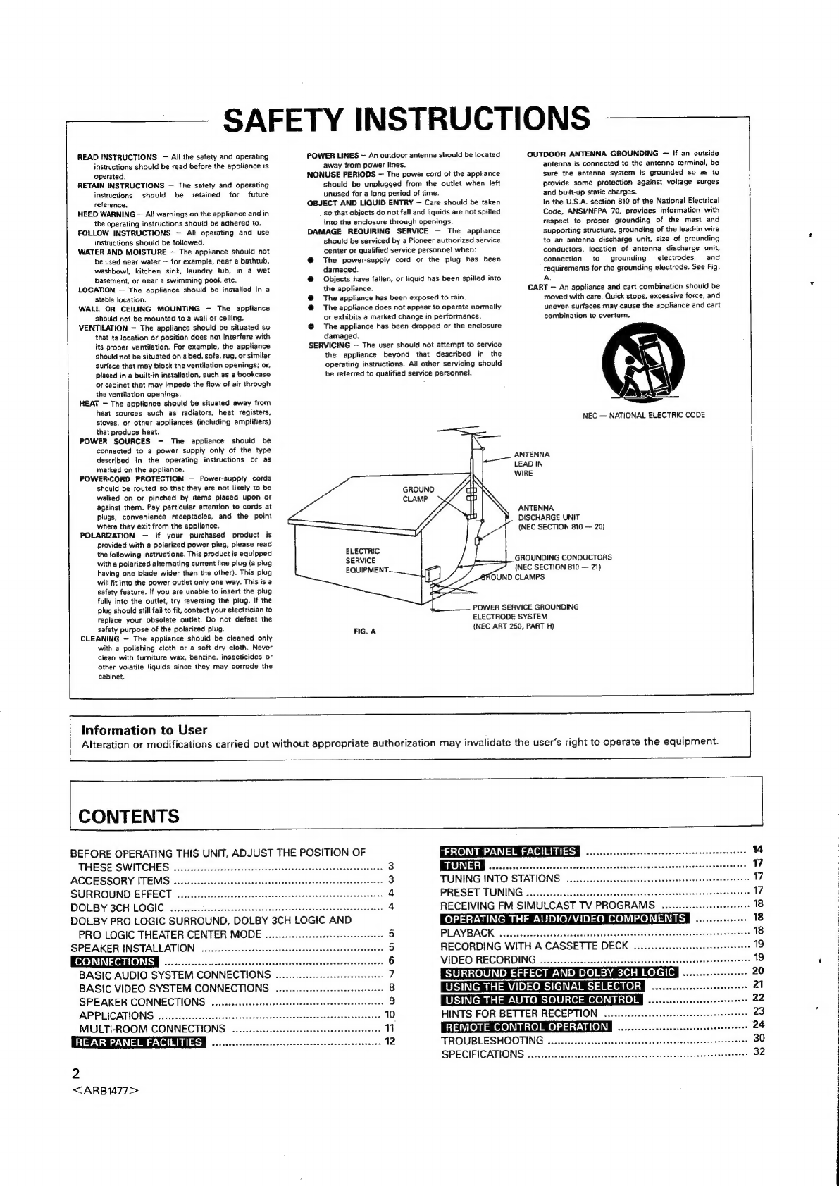
OUTDOOR
ANTENNA
GROUNDING
—
If
an
outside
antenna
is
connected
to
the
antenna
terminal,
be
sure
the
antenna
system
is
grounded
so
as
to
provide
some
protection
against voltage
surges
and
built-up
static
charges.
In
the
U.S.A.
section
810
of
the
National
Electrical
Code,
ANSI/NFPA
70,
provides
information
with
respect
to
proper
grounding
of
the
mast
and
supporting
structure,
grounding
of
the
lead-in
wire
to
an
antenna
discharge
unit,
size
of
grounding
conductors,
location
of
antenna
discharge
unit,
connection
to
grounding
electrodes,
and
requirements
for
the
grounding
electrode.
See
Fig.
A.
CART
—
An
appliance
and
cart
combination
should
be
moved
with
care.
Quick
stops,
excessive
force,
and
uneven
surfaces
may
cause
the
appliance
and
cart
combination
to
overturn.
ay
NEC
—
NATIONAL
ELECTRIC
CODE
described
in
the
operating
instructions
or
as
marked
on
the
appliance.
POWER-CORD
PROTECTION
—
Power-supply
cords
should
be
routed
so
that
they
are
not
likely
to
be
watked
on
or
pinched
by
items
placed
upon
or
against
them.
Pay
particular
attention
to
cords
at
plugs,
convenience
receptacles,
and
the
point
where
they
exit
from
the
appliance.
POLARIZATION
—
{f
your
purchased
product
is
provided
with
a
polarized
power
plug,
please
read
the
following
instructions.
This
product
is
equipped
with
a
polarized
alternating
current
line
plug
(a
plug
having
one
blade
wider
than
the
other).
This
plug
will
fit
into
the
power
outlet
only
one
way.
This
is
a
safety
feature.
If
you
are
unable
to
insert
the
plug
fully
into
the
outlet,
try
reversing
the
plug.
If
the
plug
should
still
fail
to
fit,
contact
your
electrician
to
teplace
your
obsolete
outlet.
Do
not
defeat
the
safety
purpose
of
the
polarized
plug.
FIG.
A
CLEANING
—
The
appliance
should
be
cleaned
only
with
a
polishing
cloth
or
a
soft
dry
cloth.
Never
clean
with
furniture
wax,
benzine,
insecticides
or
other
volatile
liquids
since
they
may
corrode
the
cabinet.
ELECTRIC
Information
to
User
ANTENNA
LEAD
IN
WIRE
ANTENNA
DISCHARGE
UNIT
(NEC
SECTION
810
—
20)
GROUNDING
CONDUCTORS
(NEC
SECTION
810
—
21)
UND
CLAMPS
POWER
SERVICE
GROUNDING
ELECTRODE
SYSTEM
(NEC
ART
250,
PART
H)
Alteration
or
modifications
carried
out
without
appropriate
authorization
may
invalidate
the
user's
right
to
operate
the
equipment.
CONTENTS
BEFORE
OPERATING
THIS
UNIT,
ADJUST
THE
POSITION
OF
THESE
SWITCHES.
...0....
0.
eccecsecenece
cece
eeeteenescetetecesecesensenteesees
3
ACCESSORY
ITEMS
....
SURROUND
EFFECT
.
DOLBY
3CH
LOGIC
...
bss
nae,
ans
DOLBY
PRO
LOGIC
SURROUND,
DOLBY
3CH
LOGIC
AND
PRO
LOGIC
THEATER
CENTER
MODE
..............:eeeeseeseeseeseee
ee
SPEAKER
INSTALLATION
ee
BASIC
AUDIO
SYSTEM
CONNECTIONS
..
BASIC
VIDEO
SYSTEM
CONNECTIONS
SPEAKER
CONNECTIONS.
..........:c0cceceereeeenereeceeneceeceeeeueseenaee
APPLICATIONS
MULTI-ROOM
CONNECTIONS
....
REAR
PANEL
FACILITIES
3
2
<ARB1477>
“FRONT
PANEL
FACILITIES
vs
-4
bc
Stacetaebieusisniaccege
cs
TUNING
INTO
STATIONS
PRESET TUNING
RECEIVING
FM
SIMULCAST
TV
PROGRAMS
.......0.-:eeesserseoo
PLAYBACK
scotisteniencncatueroruaiaidhaecs
RECORDING
WITH
A
CASSETTE
DECK
VIDEO
RECORDING
sveenenaneecnnneees
HINTS
FOR
BETTER
RECEPTION
....
“
TROUBLESHOOTING
......-cccscesecsesssttscorsnesaesssssonssssenrsnesssnsets
SPECIFICATIONS
scaestssccrici
ncioustininnet-anmenupeeros


