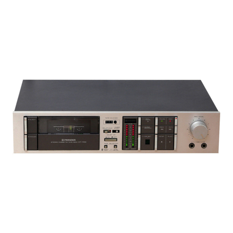
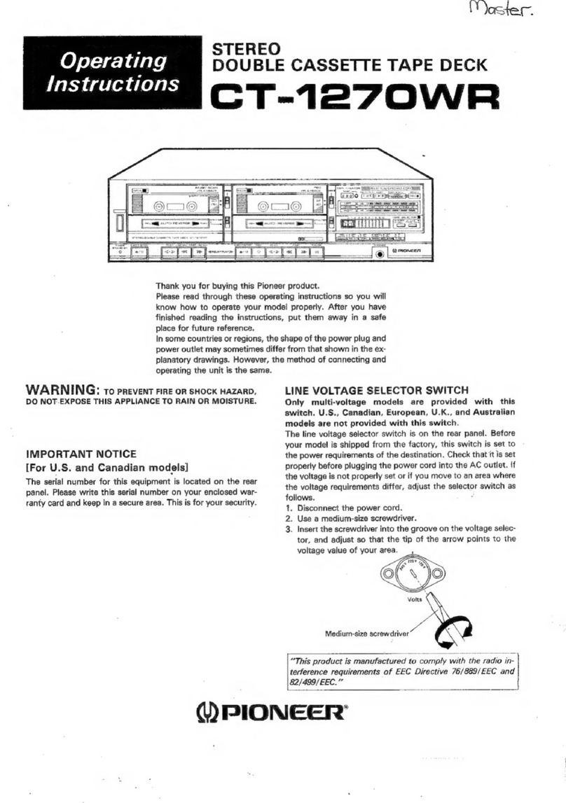
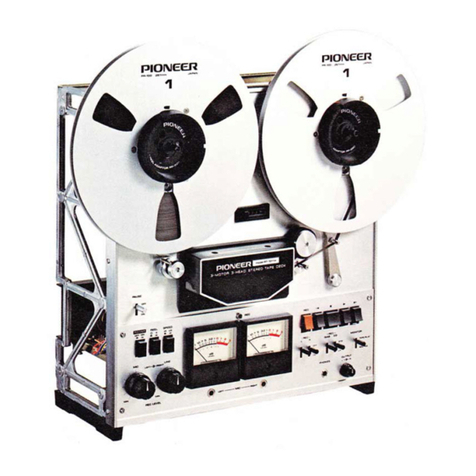
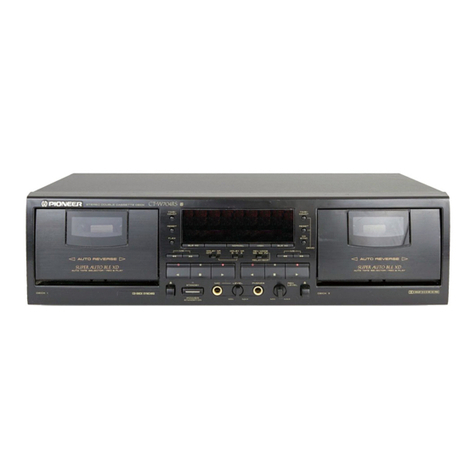
Pioneer CT-W802R User manual

@)
PIONEER’
The
Art
of
Entertainment
Service
GAL
ENIED
comm
STEREO
DOUBLE
CASSETTE
DECK
CT
-WsoeR
CT-WsS20R
CT
-W'720R
e
Refer
to
the
service
manual
ARP2547
for
CT-W801R
AND
CT-W701R.
CT-W802R,
CT-
aa
ae
AND
CT-W720R
HAVE
THE
FOLLOWING:
Power
Requirement
CT-W802R
|
CT-W820R
ti
W720R
®
This
manual
is
applicable
to
the
following:
CT-W802R/KU,
KC
and_
SD;
CT-W820R/HB
and
HEM;
CT-W720R/HEM.
AC220
—
230V,
230
—
240V
(switchable)
*
AC110V,
120
—
127V,
220V,
240V
(switchable)
*
Change
the
connection
of
the
power
transformer’s
primary
wiring.
PIONEER
ELECTRONIC
CORPORATION
4-1,
Meguro
1-Chome,
Meguro-ku,
Tokyo
153,
Japan
PIONEER
ELECTRONICS
SERVICE
INC.
P.O.
Box
1760,
Long
Beach,
California
90801
U.S.A
PIONEER
ELECTRONICS
OF
CANADA,
INC.
300
Allstate
Parkway
Markham,
Ontario
L3R
OP2
Canada
BENE
ay
atte
ge
PIONEER
ELECTRONIC
[EUROPE]
N.V.
Haven
1087
Keetberglaan
1,
9120
Melsele,
Belgium
cs
Fb
)
PIONEER
ELECTRONICS
AUSTRALIA
PTY.
LTD.
178-184
Boundary
Road,
Braeside,
Victoria
3195,
Australia
TEL:
[03]
580-9911
b
©
PIONEER
ELECTRONIC
CORPORATION
1993
SK
FEB,
1993
Printeed
in
Japan

CT-W802R,
CT-W820R
1.
CONTRAST
OF
MISCELLANEOUS
PARTS
NOTES:
¢
Parts
marked
by
“NSP”
are
generally
unavailable
because
they
are
not
in
our
Master
Spare
Parts
List.
*
The
A\
mark
found
on
some
component
parts
indicates
the
importance
of
the
safety
factor
of
the
part.
Therefore,
when
replacing,
be
sure
to
use
parts
of
identical
designation.
¢
Parts
marked
by
“@”
are
not
always
Kept
in
stock.
Their
delivery
time
may
be
longer
than
usual
or
they
may
be
unavailable.
1.1
FOR
CT-W802R/KU,
KC,
SD,
CT-W820R/HEM
AND
HB
CT-W802R/KU,
KC,
SD,
CT-W820R/HEM,
HB
and
CT-W801R/KUC
have
the
same
construction
except
for
the
following
:
>
BPPBPBR
PRZEZ
vv
UV
>
Symbol
&
Description
MAIN
unit
MAIN
unit
DISPLAY
unit
DISPLAY
unit
HP.
MIC
unit
OPERATE
SW
(1)
unit
OPERATE
SW
(2)
unit
TRANS
2
unit
Strain
relief
AC
power
cord
FU1,
FU2
Fuse
(1.5A)
FU1,
FU2
Fuse
(1.6A)
Ti
Power
transformer
(AC120V)
Ti
Power
transformer
(AC110/120
—
127/220/240V)
Ti
Power
transformer
(AC220
—
230/230
—
240V)
Voltage
selector
(AC110/120
—
127/220/240V)
Mechanism
unit
(DECK
1)
Mechanism
unit
(DECK
Il)
Function
knob
A
Door
pocket
R
Door
pocket
L
Rear
panel
Cord
clamper
Front
panel
assembly
Name
plate
Name
plate
Front
panel
Front
panel
FL
lens
Packing
case
Remote
control
unit
Battery
cover
Battery
(RO3,
AAA)
CT-wso1R/
|
CT-weo2h/
|
CT-wso2R/
|
CT-Wao2hy
|
CT-wezor
|
cT-wazory
|
Remarks
Kuc
KU KC
sD
HEM
HB
RWZ2486
RWZ2487
|
RWZ2487
RWZ2488
RWZ2489
RWZ2491
CM
—
22C
PDG1015
RWZ2488
RWZ2489
RW2Z2491
CM
—
22C
PDG1015
REK1001
|
DEK1014
RYM1169
RYM1170
RAC1714
RAH2073
RYM1207
RYM1208
RAC1807
RAH2257
RAH2076
RNA1569
RAH2258
RNA1695
RXX1518
PAM1407
RAH2079
RHG1368
RAH2079
RHG1469
Part
No.
RWZ2946
RW2Z2487
|
RWZ2487
RWZ2488
RWZ2489
RW2Z2491
CM
—
22C
PDG1015
RWZ2488
RWZ2489
RWZ2491
CM
—
22B
PDG1013
DEK1014
PSB1002
RYM1207
RYM1208
RAC1807
RAH2257
RYM1207
RYM1208
RAC1807
RAH2257
RAH2258
RNA1694
RAH2258
RNA1698
RAH2254
RAH2079
RHG1472
RAH2254
RAH2079
RHG1469
RWZ2952
RWZ2506
RWZ2507
RWZ2508
RWZ2510
CM
—
22B
PDG1003
RYM1209
RYM1210
RAC1807
RAH2257
RAH2258
RNA1696
RAH2255
RAH2080
RHG1470
RPX1057
PZN1010
RWZ2952
RWZ2506
RWZ2507
RW2Z2508
RW2Z2510
CM
—
22B
VDG1051
RYM1209
RYM1210
RAC1807
RAH2257
RAH2258
RNA1697
RAH2255
RAH2080
RHG1471
RPX1057
PZN1010

CT-W802R,
CT-W820R
Part
No.
CT-weo1R/
|
CT-wao2R/
|
CT-weo2Ry
|
cT-weo2Ri
|
cT-wezory
|
CT-wezory
|
Remarks
Kuc
KU
KC
sD
HEM
HB
RHC1037
J
MAIN
UNIT
RHC1038
RWZ2942,
RWZ3005,
RWZ2944
and
RWZ2486
have
the
same
construction
except
for
the
following:
Symbol
&
Description
Spacer
A
Spacer
B
Connection
cord
(with
mini
plug)
Operating
instructions
(English)
Operating
instructions
(English/French)
PDE
—
319|
PDE
~
319|
PDE
—
319)
PDE
—
319
RRB1120
|
RRB1124
Operating
instructions
(Spanish)
Operating
instructions
(English/French/German/italian/Dutch/
Swedish/S
panish/Portugese)
Note)*1—*3:See“1.3
EXPLODED
VIEW
AND
PACKING
”.
RRE1069
Part
No.
Remarks
RWZ2486
RWZ2942
RWZ3005
RWZ2944
2SC3311A
2SC3311A
2SC3311A
Symbol
&
Description
Q743,
Q744
D743
D910
—
D912
C741
C910
R743,
R744
CKCYF103Z50
RD1/6PM222J
R745
R746
R747
R748,
R749
R804,
R854
RCN1053
R719,
R720
JA902,
JA903
Jack
RD1/6PM332J
RKN1004
DISPLAY
UNIT
1SS254
1$S254
CEAS331M16
CKCYF103Z50
RD1/6PM102J
RD1/6PM222J
RD1/6PM223J
RD1/6PM912J
RD1/6PM103J
RD1/6PM822J
RD1/6PM332J
RKN1004
1$S254
1$S254
CEAS331M16
CKCYF103Z50
RD1/6PM102J
RD1/6PM222J
RD1/6PM223J
RO1/6PM912J
RD1/6PM103J
RD1/6PM822J
RD1/6PM222J
RKN1004
1SS254
RD1/6PM102J
RD1/6PM222J
RD1/6PM223J
RD1/6PM912J
RD1/6PM103J
RD1/6PM822J
RD1/6PM222J
RWZ2946,
RWZ2952
and
RWZ2490
have
the
same
construction
except
for
the
following:
*
Remarks
RWZ2490
RWZ2946
RWZ2952
HP.
MIC
UNIT
HC
—
177
RSG1034
Although
RWZ2506
and
RWZ2487
are
different
in
part
number,
they
consist
of
the
same
components.
:
Symbol
&
Description
11501
$1509
(FADE
OUT)
1501
RSG1034
RAW1105
RAW1105
RAW1107
OPERATE
SW
(1)
UNIT
Although
RWZ2507
and
RWZ2488
are
different
in
part
number,
they
consist
of
the
Same
components.
3

T-W802R,
CT-W820R
OPERATE
SW
(2)
UNIT
Although
RWZ2508
and
RWZ2489
are
different
in
part
number,
they
consist
of
the
same
components.
TRANS
2
UNIT
Although
RW2Z2510
and
RWZ24971
are
different
in
part
number,
they
consist
of
the
same
components.
MECHEANISM
UNIT
(DECK
1!)
RYM1207,
RYM1209
and
RYM1169
have
the
same
construction
except
for
the
following:
Remarks
RYM1169
RYM1207
RYM1209
Washer
RBF1044
ff
veers
fe
ee
ee
Gear
play
RNK1720
Arm
play
L
assembly
RXA1405
|
tee
ee
fn
ees
Arm
play
R
assembly
RXA1406
|
tte
ee
fn
eee
Arm
playo
tee
RNK1866 RNK1866
Arm
playR
fn
ee
RNK1868
RNK1868
Switch
mode
RSN1020
RSN1022 RSN1022
Solenoid
RXP1017
RXP1020
RXP1020
Motor
assembly
RXM1052
RXM1060
RXM1061
Belt
main
REB1159
REB1159
REB1162
GearFWR
nee
fn
eee
RNK1733
Flywheel
assembly
L
RXA1423
RXA1423
RXA1476
Flywheel
assembly
R
RXA1424
RXA1424
|
teres
FlywheelR
ft
eee
fn
ee
RXA1415
MECHEANISM
UNIT
(DECK
Il)
RYM1208,
RYM1210
and
RYM1170
have
the
same
construction
except
for
the
following
=
Symbol
&
Description
Remarks
RYM1170
RYM1208
RYM1210
Washer
RBF1044
Gear
play
RNK1720
Arm
play
L
assembly
RXA1405
Arm
play
R
assembly
RXA1406
Arm
play
L
RNK1866
RNK1866
Arm
play
R
RNK1868
RNK1868
Symbol
&
Description
Switch
mode
RSN1020
RSN1022
RSN1022
Motor
assembly
RXM1052
RXM1060
RXM1061
Solenoid
RXP1017 RXP1020
RXP1020
Belt
main
REB1159 REB1159
REB1162
Gear
FW
R
:
RNK1733
Flywheel
assembly
L
RXA1423 RXA1423
RXA1476
Flywheel
assembly
R
,
RXA1424
RXA1424
Flywheel
R
RXA1415

CT-W720R
1.2
FOR
CT-W720R/HEM
CT-W720R/HEM
and
CT-W701R/HEM
have
the
same
construction
except
for
the
following:
Symbol
&
Description
;
Remarks
CT-W701R/HEM
CT-W720R/HEM
MAIN
unit
RWZ2517
MAIN
unit
DISPLAY
unit
DISPLAY
unit
RWZ2853
Function
knob
A
RAC1824
RAC1806
Door
pocket
R
RAH2074
RAH2219
Door
pocket
L
RAH2077
RAH2259
Front
panel.
RAH2067
Front
panel
RAH2256
Rear
panel
RNA1574
RNA1689
Name
plate
PAM1407
Name
plate
RAM1007
Cord
clamper
RNH
—
184
Mechanism
unit
(DECK
1)
RYM1172
RYM1209
Mechanism
unit
(DECK
1)
RYM1173
RYM1210
Front
panel
assembly
RXX1519
Packing
case
RHG1372
RHG1473
Operating
instructions
RRE1063
RRE1069
(English/French/Germanjitalian/Dutch/Swedish/
Spanish/Portuguese)
Note)
*1:
See
“1.3
EXPLODED
VIEW
AND
PACKING”.
MAIN
UNIT
RW2Z2945
and
RWZ2517
have
the
same
construction
except
for
the
following:
Symbol
&
Description
Remarks
RWZ2517
RWZ2945
Q743,
Q744
2SC3311A
D743
1$S254
C741
.
CEAS331M16
R743,
R744
RD1/6PM102J
R745
RD1/6PM222J
R746
RD1/6PM223J
R747
RD1/6PM912J
R748,
R749
RD1/6PM103J
R804,
R854
RCN1053
RD1/6PM822J
DISPLAY
UNIT
RW2Z2953
and
RWZ2521
have
the
same
construction
a
for
the
following:
Symbol
&
Description
Remarks
RWZ2521
|
wees
|
Rt
$1509
(FADE
OUT)

CT-W720R
MECHANISM
UNIT
(DECK
1)
RYM1209
and
RYM1172
have
the
same
construction
except
for
the
following:
Symbol
&
Description
Remarks
Washer
RBF1044
Gear
play
RNK1720
Arm
play
L
assembly
Arm
play
R
assembly
Arm
play
L
RNK1866
Arm
play
R
RNK1868
Switch
mode
RSN1020
RSN1022
Motor
assembly
RXM1051
RXM1061
Solenbdid
RXP1017
RXP1020
MECHANISM
UNIT
(DECK
II)
RYM1210
and
RYM1173
have
the
same
construction
except
for
the
following:
Symbol
&
Description
Remarks
RYM1173
RYM1210
Washer
RBF1044
Gear
play
RNK1720
Arm
play
L
assembly
:
RXA1405
Arm
play
R
assembly
RXA1406
Arm
play
L
RNK1866
Arm
play
R
RNK1868
Switch
mode
RSN1020
RSN1022
Motor
assembly
;
RXM1051
RXM1061
Solenoid
RXP1017
RXP1020

CT-W802R,
CT-W820R,
CT-W720R
1.3
EXPLODED
VIEW
AND
PACKING
@
EXPLODED
VIEW
*1
Cord
clamper
(RNH
—
184)
@
PACKING
AND
PARTS
LIST
Parts
List
(CT-W820R/HB
type
only)
Mark
No.
Description
Part
No.
I
ev
weee
2
Connection
cord
RDE1002
assembly
3
weneee
4
Operating
instructions
RRB1124
5
Pad
(R)
RHA1045
6
Pad
(F)
RHA1088
7
Packing
case
RHG1471
8
Sheet
RHX
—
034
9
Control
cord
RDE1030
¥*2
10
Spacer
A
RHC1037
*3
11
Spacer
B
RHC1038
12
Remote
control
RPX1057
(includes
No.13)
13
‘Battery
cover
PZN1010
NSP
14
Battery
(RO3,
AAA)
VEM
—
022
NSP
15
Warranty
card
ARW
—
088

=m
10%)
CT-W802R,
CT-w820R,
CT-w720R
ff
1.4
SCHEMATIC
AND
PCB
DIAGRAM
*
CT-W802R/KU,
KC,
SD,
CT-W820R/HEM,
HB
and
CT-W801R/KUC
are
the
same
as
@
SCHEMATIC
DIAGRAM
MAIN
UNIT
B74)
R708
'
'
s
3
ve
rt)
w
s
tf
2
1@
vy
O14
1
rs
1
f
2502144
'
=
147
f
X
'
N
&S
[|
R74
lo
”,
'
'
3
x
1
rs
7
bod
'
=
‘
3
[so
2.
2
Wy
2802144:
©)
XO)
a
§ ’
‘701
Ads
A
sae
«
fy
a
h_F?
BS
Se
3
at
077
6}
Las
a
=
y
of
@
if
z=3
2
z
28
els
—<
335
Bi
¥
R
ON
N
,
rd
py
x
8
N
&
yy
=
Ts:
&
a
8
DTC124ES
R708
2
R710
=
Bsb21ees-
\k
Jy,
GSH
©
Reh
1C251,
CXA1330S—-P
-
DOLBY
B/C
NR
ong
Bae
<
wat
P|
Pee
7
Ty
Bagg
goaasblalls
?
JA701
(174)
JAT701
(
(ar)
i
YA704
(274)
JA7O1
(474)
or
Deen
tnt
ee
==
—
|
nd
Addy
did
see
|
[53/5
ek
aaa
Ea
Lemont
ll
mn
MIECa
SIR
ate
Te”
Swe
a
Ter
te
wis
Sle
wothe
mw
ater
eS
RAREHARGS
BRR
©
ahaH
LER
LEREREC.
i_-CT-W820R
ONLY
rte
tote
fon
vie
|
go
ook
ENS
U3
eed
Bee
d
<
cT-weoer,
SRiyeeon
$1801~1509:
1034
114TS
ms

___]
1
[
2
@
PCB
DIAGRAM
CT-W802R,
CT-W820R,
CT-W720R
DISPLAY
UNIT
£C9*tU|
F
oases
NE
CO
LO)
[ty
|
|
|
|
|
|
fo
ree
|
Q743
Q744
4
La
toot
MAIN
UNIT
Fe
™,
ee
ee
ee
ee
ee

WpiIonceR
ss
UU
The
Art
of
Entertainment
Service
ORDER
NO.
ARP2547
STEREO
DOUBLE
CASSETTE
DECK
CT-WsoirR
CT-WessiR
CT-W701IR
CT-wWs01R,
CT-W851R
AND
CT-W701R
HAVE
THE
FOLLOWING:
ie
ee
eee
wen
CT-W801R
|
CT-W851R
|
CT-W701R
AC220
—
230V,
230
—
240V
(Switchable)
*
FP
AC110V,
120
~
127V,
220V,
240V
(Switchable)
Co
een
eo
*
Change
the
connection
of
the
power
transformer’s
pimnary
wiring.
e
This
manual
is
applicable
to
the
following:
CT-W801R/KUC,
KUC/CA,
and
SD;
CT-W851R/HEM
and
HB;
CT-W701R/KUC,
KUC/CA,
HEM
and
HB.
@
For
the
following:
CT-W801R/SD;
CT-W851R/HEM
and
HB,
refer
to
page
63.
For
the
following:
CT-W701R/HEM
and
HB,
refer
to
page
65.
e
Ce
manuel
pour
le
service
comprend
les
explications
de
réglage
en
frangais.
e@
Este
manual
de
servicio
trata
del
método
ajuste
escrito
en
espanol.
@
KUC/CA
type
is
identical
to
KUC
type
with
French
instruction
manual.
For
all
information
except
for
the
instruction,
refer
to
KUC
type.
PIONEER
ELECTRONIC
CORPORATION
4-1,
Meguro
1-Chome,
Meguro-ku,
Tokyo
153,
Japan
PIONEER
ELECTRONICS
SERVICE
INC.
P.O.
Box
1760,
Long
Beach,
California
90801
U.S.A.
PIONEER
ELECTRONICS
OF
CANADA,
INC.
300
Allstate
Parkway
Markham,
Ontario
L3R
OP2
Canada
PIONEER
ELECTRONIC
[EUROPE]
N.V.
Haven
1087
Keetberglaan
1,
9120
Melsele,
Belgium
:
PIONEER
ELECTRONICS
AUSTRALIA
PTY.
LTD.
178-184
Boundary
Road,
Braeside,
Victoria
3195,
Australia
TEL:
[03]
580-9911
AY
I
©
PIONEER
ELECTRONIC
CORPORATION
1992
SI
MAY
1992
Pnged
in-dstan

CT-W801R,
CT-W701R
CONTENTS
1.
SAFETY
INFORMATION
evsssrertsresreeeeseseeereeeeeeneee
2
2,
EXPLODED
VIEWS
AND
PARTS
LIST
--+e-++++-2-++**
3
3.
PACKING
AND
PARTS
LIST
«vressrssereeserteeeeeeet
ee
eees
9
4.
SCHEMATIC
DIAGRAMS
--rr-sesreeeeereteeeeee
ree
econo
ees
10
5.
PCB
CONNECTIONS
DIAGRAM?
++++erererererr
ere
eeeee
17
6.
BLOCK
DIAGRAM
-0---eeeeeeeeeeeesseeeeteeneseeteeeeneeeees
25
7.
PCB
PARTS
LIST
-----eeeeseeereesesseeeeeesenneseeseeeeeeees
26
B.
ADJUSTMENTS
--eeeesseeeeeeeteeeeeeecessreeeeeeeeneeneeres
31
B.
PREGLAGES
ceveeeeeeeereeereceesseeeeeesensreeeeesesseeeenanens
35
B.
ASUSTES
coreccecceseeeeeeterseseeseeneeeeeseassneseteeneeeeeees
39
9.
IC
DESCRIPTIONS
----e-eeccceccereeeeceeeeceecceeecsanseees
43
10.
CIRCUIT
DESCRIPTIONS
-++-0-sseeeeeescesseesseeeseeees
61
11.
FOR
CT-W801R/SD,
CT-W851R/HEM
AND
HB®
TYPES
isecscscsteeesscccateeeconseverett
cecared
63
12.
FOR
CT-W701R/HEM
AND
HB
TYPES--++++-+++++
65
13.
PANEL
FACILITIES
chee
cree rece
reen
cece
eeeenceneceseneneseees
67
14.
SPECIFICATIONS
-+resesesseesevsreerecereeserecsessoeserees
68
This
service
manual
is
intended
for
qualified
service
technicians;
it
is
not
meant
for
the
casual
do-it-yourselfer.
Qualified
technicians
have
the
neces-
sary
test
equipment
and
tools,
and
have
been
trained
to
properly
and
safely
repair
complex
products
such
as
those
covered
by
this
manual.
Improperly
performed
repairs
can
adversely
affect
the
safety
and
reliability
of
the
product
and
may
void
the
warranty.
If
you
are
not
qualified
to
perform
the
repair
of
this
product
properly
and
safely,
you
should
not
risk
trying
to
do
so
and
refer
the
repair
to
a
qualified
service
technician.
WARNING
Lead
in
solder
used
in
this
product
is
listed
by
the
California
Health
and
Welfare
agency
as
a
known
reproductive
toxicant
which
may
cause
birth
defects
or
other
reproductive
harm
(California
Health
&
Safety
Code,
Section
25249.5).
When
servicing
or
handling
circuit
boards
and
other
components
which
contain
lead
in
solder,
avoid
unprotected
skin
contact
with
the
solder.
Also,
when
soldering
do
not
inhale
any
smoke
or
fumes
produced.
1.
SAFETY
INFORMATION
(FOR
USA
MODEL
ONLY)
1.SAFETY
PRECAUTIONS
The
following
check
should
be
performed
for
the
continued
protection
of
the
customer
and
service
technician.
LEAKAGE
CURRENT
CHECK
Measure
leakage
current
to
a
known
earth
ground
(water
pipe,
conduit,
etc.)
by
connecting
a
leakage
Current
tester
such
as
Simpson
Model
.229-2
or
equivalent
between
the
earth
ground
and
all
exposed
metal
parts
of
the
appliance
(input/output
terminals,
screwheads,
metal
overlays,
control
shaft,
etc.).
Plug
the
AC
line
cord
of
the
appliance
directly
into
a
120V
AC
60Hz
outlet
and
turn
the
AC
power
switch
on.
Any
current
measured
must
not
exceed
0.5mA.
Reading
should
Leakage
|
Not
be
above
current
|
9.5mA
tester
Test
all
exposed
metal
surfaces
2-wire
cord
Also
test
with
plug
reversed
(Using
AC
adapter
ground
plug
as
required)
AC
Leakage
Test
‘()
ANY
MEASUREMENTS
NOT
WITHIN
THE
LIMITS
OUTLINED
ABOVE
ARE
INDICATIVE
OF
A
PO-
TENTIAL
SHOCK
HAZARD
AND
MUST
BE
COR-
RECTED
BEFORE
RETURNING
THE
APPLIANCE
TO
THE
CUSTOMER.
2.PRODUCT
SAFETY
NOTICE
Many
electrical
and
mechanical
parts
in
the
appli-
ance
have
special
safety
related
characteristics.
These
are
often
not
evident
from
visual
inspection
northe
protection
afforded
by
them
necessarily
can
be
ob-
tained
by
using
replacement
components
rated
forrol-
tage,
wattage,
etc.
Replacement
parts
which
have
these
special
safety
characteristics
are
identified
in
this
Service
Manual,
Electrical
components
having
such
features
are
identified
by
marking
with
a
A
on
the
schematics
ind
on
the
parts
list
in
this
Service
Manual.
The
use
of
a
substitute
replacement
component
wich
dose
not
have
the
same
safety
characteristics
ashe
PIONEER
recommended
replacement
one,
shown
in
the
parts
list
in
this
Service
Manual,
may
create
shock,
fire,
or
other
hazards.
Product
Safety
is
continuously
under
review
and
new
instructions
are
issued
from
time
to
time.
F
or
the
latest
information,
always
consult
the
curr
nt
PIONEER
Service
Manual.
A
subscription
to,
or
a
d-
ditional
copies
of,
PIONEER
Service
Manual
maybe
obtained
at
a
nominal
charge
from
PIONEER.

2.
EXPLODED
VIEWS
AND
PARTS
LIST
EXTERIOR
(CT-W801R/KUC,
KUC/CA
AND
CT-W701R/KUC,
KUC/CA
TYPES)
2.1
NOTES:
e
Parts
m:
°
The
A
to
use
p
¢
Parts
m:
Parts
lL
Mark
44
dd
©0O
23°
SS
27
CT-W701R
CT-W801R
ry
CT-W801R
onl
4106
_
CT-W801R
only

|
;
|
_
|
6
L
CT-W801R,
CT-W701R
NOTES:
©
Parts
marked
by
“NSP”
are
generally
unavailable
because
they
are
not
in
our
Master
Spare
Parts
List.
*
The
A\
mark
found
on
some
component
parts
indicates
the
importance
of
the
safety
factor
of
the
part.
Therefore,
when
replacing,
be
sure
A
to
use
parts
of
identical
designation.
e
Parts
marked
by
“@”
are
not
always
kept
in
stock.
Their
delivery
time
may
be
longer
than
usual
or
they
may
be
unavailable.
Parts
List
Mark
No.
Description
Part
No.
Mark
No.
Description
Part
No.
A
Strain
relief
CM
—
22C
NSP
101
PCB
spacer
PNY
—
404
A
2
AC
power
cord
PDG1015
NSP
102
PCB
spacer
(rubber)
REB1201
:
3
Lead
card
24P
RDD1265
NSP
103.
Main
chassis
RNB1070
—
A
4
FU1,
FU2
Fuse
(1.5A)
REK1001
NSP
104.
SW
bracket
RNE1441
A
5
Power
transformer
RTT1165
NSP
105
Mechanism
shield
plate
RNE1519
©
6
Mechanism
unit
(Deck
I)
RYM1169
NSP
106
Shield
case
RNE1520
©
7
Mechanism
unit
(Deck
II)
RYM1170
(CT-W801R
only)
8
Door
spring
L
RBH1304
NSP
107
Name
plate
PAM1407
9
Door
spring
R
.
RBH1305
108
e+ee
10
Half
pressure
spring
RBK1004
NSP
109
Front
panel
RAH2065
(CT-W801R)
B
11
Damper
assembly
REC1005
NSP
Front
panel
RAH2067
'
12
Insulator
(CT-W801R)
PNW1912
(CT-W701R)
13
Foot
assembly
PXA1201
NSP
110
Rear
panel
RNA1569
(CT-W701R)
(CT-W801R)
14
Counter
knob
RAC1426
NSP
Rear
panel
RNA1573
15
Power
knob
RAC1712
(CT-W701R)
16
Slide
knob
RAC1713
NSP
111
MAIN
unit
RW2Z2486
17
Function
knob
A
RAC1714
(CT-W801R)
(CT-W801R)
NSP
MAIN
unit
RW2Z2511
_
Function
knob
A
RAC1716
(CT-W701R)
(CT-W701R)
NSP
112
HP,
MIC
unit
RW2Z2487
18
Function
knob
B
RAC1717
(CT-W801R)
19
VR
knob
RAC1719
NSP
HP
unit
RW2Z2512
20
Eject
knob
RAC1722
(CT-W701R)
NSP
113.
OPERATE
SW
(1)
unit
RW2Z2488
21
Door
pocket
R
RAH2073
(CT-W801R)
(CT-W801R)
NSP
OPERATE
SW
(1)
unit
RWZ2513
Door
pocket
R
RAH2074
(CT-W701R)
C
(CT-W701R)
NSP
114
OPERATE
SW
(2)
unit
RW22489
22
Door
pocket
L
RAH2076
(CT-W801R)
(CT-W801R)
NSP
OPERATE
SW
(2)
unit
RW2Z2514
Door
pocket
L
RAH2077
(CT-W701R)
(CT-W701R)
NSP
115
DISPLAY
unit
RW2Z2490
23
Remain
display
paper
REE
-
113
(CT-W801R)
24
FL
lens
RAH2079
NSP
DISPLAY
unit
RWZ2515
25
Door
lens
RAH2086
(CT-W701R)
26
Screw
BBZ20P040F
MC
NSP
116
TR
SEC
unit
RW2Z2491
—
27
Screw
BBZ30PO60FZK
(CT-W801R)
28
Screw
BBZ30P080FMC
NSP
TR
SEC
unit
RWZ2516
29
Screw
IBZ30P150FCU
(CT-W701R)
30
Screw
PMA30P060FMC
NSP
117
REC
(1)
unit
RWX1065
:
(CT-W801R
only)
31
Cord
clamper
REC
—
371
NSP
118
REC
(2)
unit
RWX1066
32
Front
panel
assembly
RXX1518
(CT-W801R)
(CT-W801R)
NSP
REC
unit
RWX1057
Front
panel
assembly
RXX1519
(CT-W701R)
(CT-W701R)
D
33
Bonnet
assembly
RXX1521
Bs
CT-W801R
4
5

|
;
|
2
|
3
Mechanism
Unit
CT-W801R,
CT-W701R
2.2
MECHANISM
UNIT
.
(CT-W801R/KUC,
KUC/CA,
SD,
CT-W701R/KUC
AND
KUC/CA
TYPES)
Parts
List
A
Mark
No.
Description
Part
No.
Mark
No.
Description
Part
No.
1
ASS’Y
HOLDER
HEAD
RXA1477
46
P.C.
BOARD
RNP1348
2
FLAME
HEAD
RNKI1715
47
HOUSING
RKP1397
38
LEVER
HEAD
RNK1716
48
EJECT
LEVER
R
RNK1703
4
SPRING
AZIMUTH
RBK1006
(DECK
1)
5
ASS’Y
ARM
ASSIST
RXAI401
EJECT
LEVER
L
RNK1702
(DECK
Il)
ile
6
GEAR
ARM
HEAD
RNK1717
49
COLLAR
RNK1704
7
SPRING
CASSETTE
RBK1039
50
WIRE
HEAD
(DECK
I)
RKP1505
8
EJECT
LOCK
RNK1718
WIRE
HEAD
(DECK
II)
RKP1399
9
CAP
REEL
RNK1719
10
ASS'Y
PINCH
ARM
L
RXA1403
61
SPRING
RBH1282
62
SPRING
RBH1283
11
CHASSIS
HEAD
RNE1437
63
SPRING
RBH1284
12
ASS’Y
PINCH
ARM
R
RXA1404
64
SPRING
RBH1286
13.
ASS'Y
ARM
PLAY
L
RXA1405
65
SPRING
RBH1288
14.
GEAR
PLAY
RNK1720
B
15
ASS’Y
ARM
PLAY
R
RXA1406
66
SPRING
RBH1290
67
SPRING
RBH1285
16
CHASSIS
0S
RXA1411
68
SPRING’
RBH1287
17
ASS'Y
SUB
REEL
L
RXA1407
69
SPRING
RBH1289
aN
18
SOLENOID
RXP1017
70
SPRING
RBH1291
19
WIRE
RDC1006
20
ARM
RVS
RNK1721
71
SPRING
RBH1292
72
FWR
SPRING
RBH1061
21
GEAR
FF
RNK1723
73
FWF
SPRING
RBH1325
=
22
ASS’Y
ARM
FR
RXA1412
74
SPRING
(DECK
I)
RBH1293
23
ASS'Y
PULLEY
FR
RXA1413
SPRING
(DECK
II)
RBH1294
24
BELT
FR
REB1158
25
METAL
RNG1048
81
SCREW
(AZIMUTH)
RBA1023
82
SCREW
RBA1027
26
ASS’Y
FLYWHEEL
L
RXA1423
83
SCREW
RBA1030
27
METAL
RNG1005
84
SCREW
PCZ20P040F
MC
28
ARM
BRAKE
RNK1724
85
SCREW
RBA1093
29
ASS’Y
SUB
REEL
R
RXA1408
30
ARM
TRIGGER
RNK1722
86
SCREW
RBA1094
Cc
87
SCREW
RBA1086
31
GEAR
CAM
RNK1725
88
SCREW
RBA1095
32
METAL
RNG1049
33
ASS’Y
FLYWHEEL
R
RXA1424
101.
WASHER
RBF1044
34
METAL
RNG1004
102
WASHER
RBF
1046
35
WIRE
RDD1257
103
WASHER
WA26D047D013
NSP
36
HOLDER
WIRE
RNK1683
37
P.C.
BOARD
RNP1347
38
SWITCH
MODE
RSN1020
—
39
SWITCH
(LEAF)
RSN1019
40
HALL
IC.
DN6851A
41
BRACKET
FW
RNE1438
Vr
43
ASS’'Y
MOTOR
RXM1052
NSP
44
WIRE
RDD1012
45
BELT
MAIN
REB1159
D
6
7
=
ee]
N
=
Ww
—

6
Mechanism
Unit
essa
+)
ES
AX
WY
Q

CT-W801R,
CT-W701
3.
PACKING
AND
PARTS
LIST
NOTES:
¢
Parts
marked
by
“NSP”
are
generally
unavailable
because
they
are
not
in
our
Master
Spare
Parts
List.
«The
A\
mark
found
on
some
component
parts
indicates
the
importance
of
the
safety
factor
of
the
part.
Therefore,
when
replacing,
be
sure
to
use
parts
of
identical
designation.
Parts
marked
by
“©”
are
not
always
kept
in
stock.
Their
delivery
time
may
be
longer
than
usual
or
they
may
be
unavailable.
Parts
List
(CT-W801R/KUC,
KUC/CA
and
CT-W701R/KUC,
KUC/CA
types)
Mark
No.
Description
Part
No.
1
Connection
cord
PDE
—
319
(with
mini
plug)
2
Connection
cord
RDE1002
assembly
8
Control
cord
RDE1030
4
Operating
instructions
RRB1120
(English
:
KUC)
Operating
instructions
RRE1064
(English/French
:
KUC/CA)
5
Pad
(R)
RHA1045
6
Pad
(F)
RHA1088
7
Packing
case
(CT-W801R)
RHG1368
Packing
case
(CT-W701R)
RHG1371
8
Sheet
RHX
—
034
9
Connection
cord
RDE
—
010
NSP
101
Warranty
card
ARY1044

CT-W8s01R,
CT-W851R,
CT-W701R
4.
SCHEMATIC
DIAGRAMS
1.
RESISTORS
:
Indicated
in
Q,
1/4W,
1/6W,
178W,
+5%
tolerance
unless
otherwise
noted
k:kQ,M;MQ,
(F);+1%,
(G);
+2%,
(K)
;+10%,(M)
;
20%
tolerance.
2.
CAPACITORS
:
Indicated
in
capacity
(uF)
/voltage
(V)
unless
otherwise
noted
p;
pF.
Indication
without
voltage
is
50V
except
.electrolytic
capacitor.
3.
VOLTAGE
CURRENT
:
;OC
voltage
(V)
in
stop
mode.
@mA;DC
current
in
stop
mode.
4.
OTHERS:
=»
;
Signal
route.
@;
Adjusting
point
The
A
mark
found
on
some
component
parts
indicates
the
importance
of
the
safety
factor
of
the
part.
Therefore,
when
replacing,
be
sure
to
use
parts
of
identical
designation.
%
marked
capacitors
and
resistors
have
parts
numbers.
This
is
the
basic
schematic
diagram,
but
the
actual
circuit
may
vary
due
to
improvements
in
design.
CT-W801R
and
CT-W851R
CT-W701R
5.
SWITCHES
(The
underlined
indicates
the
switch
position)
5.
SWITCHES
(The
underlined
indicates
the
switch
position)
MAIN
UNIT
MAIN
UNIT
$1201:
POWER
SW
ON
—
OFF
$1201:
POWER
SW
ON
—-
QFF
OPERATE
1
UNIT
OPERATE
1
UNIT
$1301:
FWD
$1301:
FWD
$1302:
REV
$1302:
REV
$1303:
STOP
$1303:
STOP
$1305:
FF
$1305:
FF
$1306:
REW
$1306:
REW
OPERATE
2
UNIT
OPERATE
2
UNIT
$1401:
FWD
$1401:
FWD
$1402:
REV
$1402:
REV
$1403:
STOP
$1403:
STOP
$1406:
REV
$1406:
REV
DISPLAY
UNIT
DISPLAY
UNIT
$1501:
1-REC
$1501:
1-REC
$1502:
1-PAUSE
$1502:
1-—-PAUSE
$1503:
1-—MUTE
$1503:
1-—-MUTE
$1504:
2-REC
$1504:
2-—
REC
$1505:
2-PAUSE
$1505:
2—
PAUSE
$1606:
2-MUTE
$1506:
2-—-MUTE
$1507:
1-BLE
$1507:
1-BLE
$1508:
2-BLE
$1508:
2-
BLE
$1510:
CD
SYNC
$1510:
CD
SYNC
$1511:
RESET
1-
COUNTER
$1511:
RESET
1-COUNTER
$1512:
MODE
1-COUNTER
$1512:
MODE
1-—-COUNTER
$1513:
RESET
2-COUNTER
$1513:
RESET
2-COUNTER
$1514:
MODE
2-—COUNTER
$1514:
MODE
2-COUNTER
$1615:
Xi
COPY
$1515:
X1
COPY
$1516:
X2
COPY
$1516:
X2
COPY
$1517:
PARAREC
$1518:
RELAY/SKIP
$1518:
RELAY/SKIP
$1520:
|
DOLBY
B-OQFF-C
$1520:
|
DOLBY
B-QFF-C
$1521:
tl
DOLBY
B-OFF-C
$1621:
1)
DOLBY
B-QFF-C
$1522:
CAR
—NOR-—HP
$1522:
CAR—-NOR-—HP
$1523:
TIMER
REC
-
OFF-PLAY
$1523:
TIMER
REC
~
OFF
~—
PLAY
$1524:
2-¢@-©
$1524:
2-@-O
10

aa
1
|
2
5.
PCB
CONNECTIONS
DIAGRAM
©
View
from
component
side
——-—-—-—-—-----~—~-------4
Power
supply
Section
for
SD
Type.
TR
SEC
UNIT
CN1201
A
LN
1
VOLTAGE
SELECTOR
A
POWER
TRANSFORMER
24ov_
cry!
220V__REDI
=
~
Se95y
orc!
110V_
YEL!
{
AC
AC
Bess
i
ares
eee
Eas
POWER
110/120-127/220/240V
CORD
50/60Hz
Fo--e-
Or er
er
arene
aaa
ee
ee
ia
Supply
Section
for
HEM
and
HB
Types.
TR
SEC
UNIT
|
CN1201
ao5y
|
hs
POWER
TRANSFORMER
RED
lA
le
POWER
l
CORD
|
L
|
|
ac
|
|
I
25/235V
|
50/60Hz
I
{
Line
voltage
can
be
changed
with
the
following
steps.
1.
Disconnect
the
AC
power
cord.
2.
Remove
the
top
cover.
3.
Change
the
connection
of
the
power
transformer
primary
taps.
4.
Stick
the
line
voltage
label
on
the
rear
panel.
Port
NO.
|
Description
AAX-193
|
220V
label
AAX-192
|
240V
label
|
|
|
Line
Voltage
Selection
|
|
|
|
I
a
|
|
|
|
|
|
|
|
L
TR
SEC
UNIT
A
POWER
TRANSFORMER
Ac
POWER
CORD
AC
120V
60OHz
fo
Nees
ee
as
ot
eet
che
Qn01
Q1n4
ant
Q705
1c1003
Q1103
Q1113
Q1112
Q1110
Q1109
Q@762_
IC
761
Q702
Q701
Q703
IC701
Q706
aQ709
QN63
1C1004
Q1105
Q1104
Q1102
Q331
Q101
a764
Q@741
@251
9704 Q708
a710
Q1164
01108
Q103
Q106
Q257
Q321
Q322
Q1159
Q1001
1C1002
@1107
Q1106
Q153
Q151
Q108
1C101
Q163
Q161
Q104
Q165
Q256
Q323
9324
Q1160
HF
1C1005
1c902
Q152
Q109
Q164
Q162
Q255
Q1157
Q1158
Q1005
Mais
a902
Q903
Q155
0154
Ql02 Q157
Q167
1c251
Q551
Q1155
01156
ia
Q1007
1C903
1C1701
Q171
Q172
Q252
Q552
Q1153
Q1154
ie
Q1006
1C554
Q1151
Q1152
lz
0804
fe)
sare
cokes
Scomabos
1C501
Q510
Q507
1C510
Q322
Q853
iS
BROT
OER
O08
<
085s
B
VR301
VR302
VR103
VR104
VR321
VR322
VRI01
VR551
vRss2
VR323
VR324
es
heat
VR8
MAIN
UNIT
op
te
FO}
RNZ2242
_
D
&
—
ye
pe
ae
R534
3
x501
fie
|
41
2s
:
ie
oi.
75
oo
URE:
aan
ty
NOTE:
%
1
>
CT-W80IR
Only.
%
3
(CT-W7OIR
Only.
$1403
*%
2
(CT-W801R/CT-W85IR
Only.
a
ee
3
ee
a
fests
1
5
1
it

CT-W801R,
CT-W851R,
CT-W701R
Q705
1
Q706
Q709
Q1163
4
Q708
Q710
Q1164
Q321
Q322
Q1159
Q323
Q324
Q1160
.
Q1157
Q1158
Q1155
Q1156
Q1153
Q1154
Q1151
Q1152
Po
Na
sare
Na
REC
(1)
UNIT
BIAS
euch
é
piow7e's.,
BIAS
“
1LCh
iC
2LCh
.
2RCh
RWZe51e
%
r
on
,
IC510
Q322
9853
is
«GY
Fle,
=o
Dp
Q852
Q854
a
Q855
z
2321
VR322
R323
VR324
VR852
VR851
poms
7010
MS
weaIR
ONLY)
CeBI17
«
eS
ae
RWY1Q57)
(APY
1865)
Bap
Gm
ge
CT-W7OIiR
Only.
See
a
ee
ee
ee
ta
a=75)
P.C.B.
pattern
diagram|
Corresponding
part
P.C.B,
pattern
diagram
Corresponding
part
indication
symbol
Part
name
indication
symbot
Part
name
i
=
=
Transistor
Ceramic
capacitor
ae
SZ
EQS
DAMN
ot
°
jQ1152
WSS
EY
fs
‘
af}
a
115
:
1154
“Vesy
o
;
A
RLISI
RT
TS2
:
“4
CNOB7
an
PoSCeCSE
eS
oe
OE
22238
|
a
oa
o—
}-~o
a
4)
or
fe)
FET
Cc
yy
Mylar
capacitor
8
$68
a
on
“O1TS1
¢
Styrol
capacitor
Sa
raze,
elk
Electrolytic
capacitor
o—t—o
7
o——o
cad
(Non
polarized)
Rea
£
Ww
C
co
z
Electrolytic
capacitor
1
a
(Noiseless)
pee
iS
+
Electrolytic
capacitor
(Polarized)
Electrolytic
capacitor
°°
fq
oO
Zenner
diode
eae
oi
ogo
LED
o—_
roy
Power
CT-WsoiIR,
CT-W851R
Z
Only
?
Semi-fixed
resistor
capacitor
o—-|H@-—o
Varactor
°
7
©
>,
EERE)
Resistor
array
Tact
switch
oe)
Fa
~
703A
(CT~W8O1Rd
781A
(CT-W701R3
“T
fal{})
>
(SID
+
a)
Re
oW—o
Resistor
SFT
Ho
Inductor
{-—____|
SFY
vo
Coil
SOF
|
OK
|
Resonator
T
ha
*
Oe
Transformer
‘C)
two
Thermistor
KA}
|
[Saar
|
Filter
1.
This
P.C.B,
connection
diagram
is
viewed
from
the
parts
mounted
side.
2.
The
parts
which
have
been
mounted
on
the
board
can
be
replaced
with
those
shown
with
the
corresponding
wiring
symbols
listed
in
the
above
Table,
3.
The
capacitor
terminal
marked
with
CI
shows
negative
terminal,
D)
4.
The
diode
marked
with
O
shows
cathode
side.
5.
The
transistor
terminal
marked
with
(J
shows
emitter.
YOON
O
©ODM©OO®OOOO
20
[
|
7
|
8
|
9
|
10
|
‘i
I
r

1
2
3
4
«
CT-W801R
AND
CT-W851R
vat2
varz
oral
14s
pues
OTC114TS
$s
rx!
8
TKLE
Ls
7
8
8
mas
1.
26BV
ws
ie
yajos”
RUA
C117
RIS
RN?
2
3
oft
g
2K
2.7%
.¢
0152
3
4.796
e
100710
©8
FAW
VAIZ
Z
+;
26.
26BV
al
Cute
g
d
a
S33
at
2
e
cds
af?
107
xe
25g
ze?
10-16
gas
S78
i
(eu)
sia
oag
as
=
f
r)
2
13
4B
food
ous
3
§
8
Sans
31.
248V
eae
os2
25373
ors
‘er
12
oF
oO
Lo}
LA}
tt]
4]
a
[Fe
4
£
—Ts>-
S|>
Ju
op
Seed
eed
Meee
ae
Paiste
we
shi
jase
%:
018s
orc124€s
sl.
2
{%
+
[as
&
93S
etes099
2
oro
7a
|oree
G]
f)
bd
Ea
Ewes
Gd
bo)
bod
ta
ae
cee
be
OE
peers
A)
veys
once
aT
5
ve
ise
x
is
ol
833
=
vesyv
49?
P
orarsacs
Us
z
s
1c101
PB EQ
AMP
eld
S3e
(
165
=
S
9
419
bass
(i)
eet
el
ke
D
CxA1115BP
ae
EST
des
Aiea
all
I
oes
(Sa
iet
rz
3
[38]
2
ie
4
SL)
2
Gf
val
S58
DOLBY
B/C
NR
28K373
gH)
orcr2aes
Xb
deg
|
21°
<]
va
ACI
C7:
on
954
0102
yey
$
\ve]
aa
ORT
“se
s|
abt
aa
BG
st
Of)
&
3|
oTew
3320),
S|
83S
arei039
a3,
Saag
eees
2
orci
2465
G
(TS:
Sr3-@
ol
5
=]
TO
Orr
a
a
orc12a€
bis
,
Sss@e
|
as
5
8
lo
|S
‘Ose
3S
.
18
Bt
$2
for2e
el
olf
|S
s8eal
aan
as
335
Sve
WY
Fae
F
SS
|
rg
Fe
eS
a3?
&
S|
Si"
|
Salve
4
ail
4
“Te
feberisis
tele
off
ore
Rowe
t/a
3
S3e
FHSS
RCo
ODP
FRA
pie?
Oy
tes
(8
1818
SEIS
|S
|S
aE s°
la
18
|
y
27)
..
Ri2z6
-+
ciz6
pat
é
2
[sfe}s
&
io
ag
22K
0.047
ae)
RTF1203
=
VFL
es
ra
wT
|
an
0162
gy
a]
aoa
PX
[
2°
|
25K573
4]
8
REC
B
g
vesy
% 2
& 2
-
a
7
= 2 Z
:
of
=
Fs
a
E>
e 2 7
3
=
vesv
S
e
-
=
- - = -
sy
a
=
a
2 7
=
ey
_
a
A
RTF
1203
&
OTE
24Es
6
g
=
=
5
:
z
3
ows
Td
dash
REC
EQ
AMP
|
:
ves
a
fy
(a
[8
220p
0383
(
Beoraes
!
i
GNDA
18
a
6389
Ds
ex}
aio
1
|
+
2
R2301-R2336;
(5x)
RIENIO?
REO7
341
iN
Ss
ps1
352563
ass
“
ver2
|
[18k
$128-XH-A~1
12JQ-8T
|
N352
CN3512
iy
H
voo
18
S
@
R307
RCNIOZS
hs
x
3
a
seo
fe
|
@
age
scwze
:
z
@}/®
:
acerose
wectsosiace
*5P4
QO
5
od
fo
©||©
a
©)||€
“
GNDA
os.
DIZ
B
R30
LON
2
aseg
8?
ETN
®||C
5
ists
W's.
ex]
310
R310
TO
exe
@|O
Liga
re
J
OK
|
{9
alz
2
28021445
&)
Peas
woxe
LS13
p
zsh
GNOA
«lg
Rian
2
©
Bek
5
if
opm
oa
os
ra
5
|
a
5
g
e516
L
‘
‘-
E517
os
es
oa
c
:
(Ee:
sagted
MEOIEES:
nash
nae?
Rac8
e
fate
z
0
o6a/100L
452
(Pa)
6:
43
4.7
2
¢
5 %
3S
8
2 2
5 5
R113)
RIS
i
joTc114TS
OTC
1245)
7
Ho
0353
28021445
t—
397
‘
\
cope
Nb
ie
hs
Sede
2
SRE
$128-XH-A-1
125O-8T
Baye
NORY
CN352
CN3522
&
ew
dics
y
D
ae
|
sae
|
ean
cae
aly
4%
ie
FY
&
7
|
Rape
aS.
A
et
i
ont
[a
%k
tcroy
zha
To
oi
L300
ad
&
x
R373
R374
amet
hy
ae
a
[O85
eoan
hy
mc140s1ace
ole
.
:
e
F
soz
73
|
R380
5
FA
3
[33K
T
[asx Tuer
6
5
RCP1O4S
n324
4502
3s
36
we
Coase
[ate
Ter:
: _
om
g
3
yha
She
:
=
m
|
fo
|
fog
ch
|
ct
|
cP
Bb
Se
ort
.
=
=a
‘|
z
Fy
a
4
a
f
aL
e
4
5
|
|
%
pes
2078
:
i
°
g
g
!
nceyoss
5
5
al
as
aT
g
~
1
GNDA
=
|
Z
-
VT
vai2
7
vA
i 2
o
t
'
5
2
5
S7B~XH-A~1
7JO-BT
.
f.
10SKHZ
CN405
cass
|
0
GRR
r09
L452
@
asoe
1
to)
@
gsag
2CR
@)
-
ee
a
irzaie
|
PTO1087
‘2MET
®
'
2B1AS
2B1AS
|
[-
6)
BIAS
Ses
©
\
osc
era
6)
2cA0
E
ate
aa
BS
|
'
i
=
:
1
CN451
|
:
1
|
=
cee
ees
a=
thas
mibey
==
res
-=
a
==
og
Bias
—
2
Ris
oo
a
aes
|
VAIZ
vco12
:
POWER
SW
51201
A
POWER
SW"
RSA-063
HEM,
HB
RSA-063
oa
eho
A
1208
AC
220~230/230~240V
Ciabs
al
A
s
-
2 2 7
e e a
-
38
WoaTei2FA
tuaw7e1
26
>
50/60Hz
A
7
Se
WE
01012}
s2vez0
161903
11008
——
ace-008
pco-009
g
:
7
2
|
4
= =
-
E
é
2
turgor
pect
etter
reee
i
|
J1001
cS
A
perry
OLO
LO)
Rar
eres
aa
:
[
w«c-028
A
;
|
6
ta
et
Ee
wagro28
‘anit
:
t
A
Funes
ie
*
!
aa
7
rear
@))
|
|
TF
i
euio02
|
q
:
|
7
we
1
aa
Ne
Q} |@
Shr
GSH
nk,
‘
|
| |
J
po0c10030———
=
i
1
4)|
|@
caipacazos
penpeueRa
ee
Rik
A
RTT1166
A
|
1
KUC,KUC/CA
'
i
©}
|©
A020
BLGoR
01906
{
4
*
z 2 = 2
é
2
'
i
©
1sR35-1o0AM|
power
sw
A
ax
hes
AC120V
GOHZ
'
‘a
©
i.
sizoi
|
SD
H
ive
:
i
@|
|@
sd
A
AC110/120~127/220/240V
' t
3s
NEUTRAL
'
i
©)
©
cool
ba
RCG-008
50/60Hz
;
'
'
J1001A
vesv
7
y : 2
-
7
7
4
POGt908
BOERS
-
|
TR
SEC
UNIT
| |
[1201
F
[
eee
&
RTT1167
AL
TRANSFORMER
:
‘
it
q
A
RTT1165
|
Le
ah
T
\
1
'
ime
2 .
oo
t
Mo
i
|
POG1013
'
=
“
re
ed
>
Ht
oo
-
- -
~
~
=
g
en
=
y
FU1001,
FU1002
H
it
71.6A4L250V
HEM,
He,
SO
|
1
|
1.5A/125V—
KUC
f
a
This manual suits for next models
2
Table of contents
Other Pioneer Tape Deck manuals

Pioneer
Pioneer CT-5151 User manual

Pioneer
Pioneer RT-707 User manual

Pioneer
Pioneer CT-F1000 User manual

Pioneer
Pioneer RT-1011L User manual

Pioneer
Pioneer CT-5 User manual

Pioneer
Pioneer D-07 User manual

Pioneer
Pioneer CT-730 User manual

Pioneer
Pioneer T-6600/F User manual

Pioneer
Pioneer CT-F600 User manual

Pioneer
Pioneer CT-9R User manual

Pioneer
Pioneer CT-970 User manual

Pioneer
Pioneer CT-4 User manual

Pioneer
Pioneer CT-055W User manual

Pioneer
Pioneer CT-F700 User manual
Pioneer
Pioneer RT-1020L User manual

Pioneer
Pioneer CT-40 User manual

Pioneer
Pioneer RT-2022 User manual

Pioneer
Pioneer CT-501 User manual

Pioneer
Pioneer RT-909 User manual

Pioneer
Pioneer CT-F9191 User manual