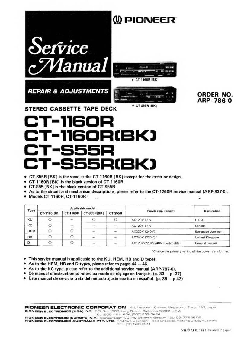
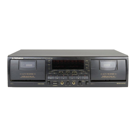
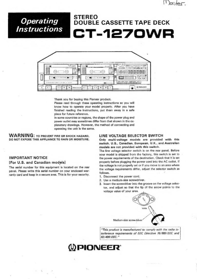
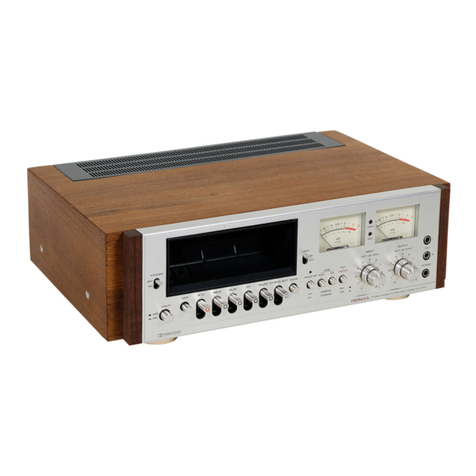
Pioneer CT-5 User manual

STEREO
CASSETTETAPE
DECK
(DrrloNEEFl'
ORDER
NO.
ART-
678-O
9. SCHEMATICDIAGRAM 21
10. PARTS
LIST . 24
11.
MECHANICALADJUSTMENTS ...... 27
al
REGLAGESMECANIOUES.... 29
t
AJUSTESMECANICOS .....31
12.ELECTRICAL
ADJUSTMENTS 33
at
REGLAGESELECTRIOUES... 37
,
AJUSTESELECTRTCOS
.... ....... 4.1
I
I
CONTENTS
1. SPECTFTCATTONS. .... . 2
2. FRONTPANELFACILITIES .....3
3. DISASSEMBLY... ......4
4. PARTSLOCATION ....6
5. EXPLODEDVIEWSANDPARTSLIST
.. .. . .
.. 8
6. PACKING 14
7. BLOCKDIAGRAM ...... 15
8. P.C.
BOARDCONNECTIONDIAGRAM
.... .. 17
lr rl
f.-r
This
servicemanualisapplicableto the KUtype.Forservicing
of theothertypes,
please
refer
to theaddi-
tional
servicemanual.
For the mechanism& circuitdescriptions,
pleæe
refer
to the supplementof model
CT-5servicemanual
(ARP-002).
Ce
manueld'instruction
se
refèreaumode
de
réglaç,en
français.
Estemanualde
servicio
trata
delmétodo
de
ajusteescritoenespaffol.
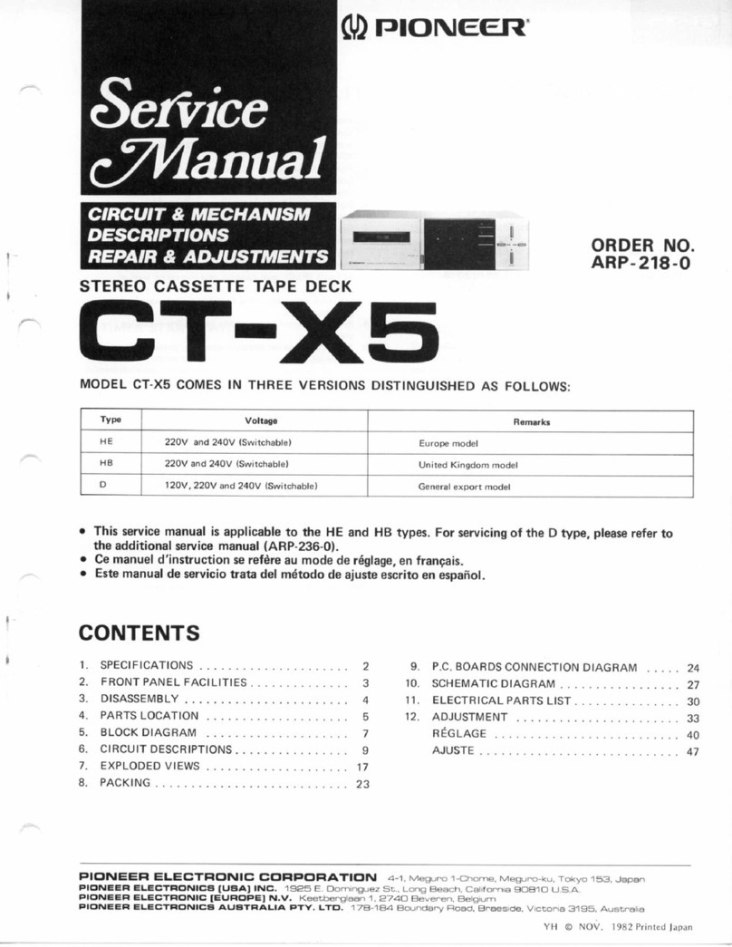
MODEL
CT-5COMESIN
SIX
VERSIONS
DISTINGUISHED
AS
FOLLOWS:
Type Volatge Remarks
KU 120V
only U.S.A.model
KC 120V
only Canadamodel
HE 22OY and 24OV (switchable) Europe model
HB 22OY and 240V (switchable) U.K. model
HP 22OV and 240V (switchable) Australia model
D12OV,22OV
and
240V
(switchable) Generalexport model
PICINEEF| ELECTF|CINIC CCIFIFOFIATICIN 4-1, MesuFo 't-chome, Mesurc-ku. Tokyo 1s3, Jep€n
1J.5. PlCt lEEFl EL.EgfFrcI\laCB OG'FIPC'F|ATIGIN 85 Oxfond Onive, Moonactrre. New Je€ey O7O74. U.S.A
IIICINEEFI H.ESfF|CINIC (EUFICTPEI N.V. LuiÈh€gen-Hêven 9, 2O3O Antwenp. Belgium
FfCINEEFI ELEgfFrclNlCA AUBTF|ALIA FÎY. L1E. 178-1EJ4 E}oundary F|oad, Ê|neesrde, VEÈonia 3195, AusEnalE
YP @MAY 198I Printed
in lapan

1.
SPECtFtCAT|ONS
Wow and Flutter No more thanO.05%
(WRMS)
Frequency Response -20 dB recording:
Normaf
, LH tap€s 20 to Î5,OOOHz
Specifications
Systems
Motor ......:
Heads
Fæt
WindingTime
Chromium dioxidetape
Metal tape
Signal-to-NoiseRatio
DolbyNR OFF . .
Dolby NR ON
compact cassette,
2.channel stereo
DC servo motor x 1
"Hard Permallay" recording/play-
back headx 1
"Ferrite" Erasing
headx 1
Approximately lOO æconds (C€0
tape)
(30
to 14,000Hz
13
dBl
20to 17,OOO
Hz
(30
to 16,000Hz
!3 dBl
(0 dB recording;
30 to 8,0OOHz)
20to |8.OOO
Hz
(3O
to 17,q)0
Hz13
dB)
(0
dBrecording;
30
to 12,5O0Hzl
More
than
50dB
BTypemore
than
68dB
CType
more
than78dB
(over
5kHz)
Miscellaneous
PowerRequirements
PowerConsumption . . . . . .
Dimensions
Weight(without pækage)
FurnishedParts
Connectioncord with
pin plugs
Operating instructions
AC
120V
60
Hz
23watts
420
(Wl
x 99.5
(Hl x
16-9/16
(w)
x 3-15/1
{D}
in.
4.5kg
(9
lb
15
ozl
(D)
mm
x 9-9/16
TT6 or
2) or
(160
ton
2
1
Harmonic
Distonion No more than 1.2%
(0dB)
Input (Sensitivity/Maximum
allowable
input/lmpedance)
MIC (L,R) . . . 0.3
mV/57 mV/10 ka,6 mm
diam.
iack
(Reterence MIC impedance;25O n
to 1OkO)
LINE (lNPUTl
x2 . . . . 50 mY/22Y11C0
ksl,
pin
jack
Output (Reference
level/Maximum
level/Load
impedancel
LINE
(OUTPUT)x2 . . . . 450mV/50kO,Pinjack
Headphones . . . . . 65mV/160mV/8O,6mmdiam.jack
Subfunctions
o MS (MusicSelectl system
o REC muting switch
o Dolby NR B & C system (B & C, ON/OFF) with LED indicarer
tamo
o LED peak
meter
o ALC (Aulo matic levelcontrol)
o One touch recording system
. Stand-by mechanismwith unattended recording
. Auto tapeseleclor.
(NORM/CrO, /METAL)
. Full automaticstoD
mechanism
. Noise Beduclion System manufactured under license from
Dolby Laboratories Licensing Corporatron
. "Dolby" and the double-D QQ symbol are trade marks of
Dolby Laboralories Licensing Corporation
Note:
Specifications and the design subiect to possible
without notice due to improvemen$.
NOTES:
1. Reference
Tapes: Normal & LH: DIN 4551
equ
lv.
CrO, DtN 45S13/BLATT
eoulv.
2. Reference Recording Level: Meter OdB i
nwb/m magnetic level= Philips cassettereference
Reference
Signal:
333 Hz
Wow & Flurter: o JIS [ 3 kHz, with accustic
(weighted) rms valuel DIN [3,150 Hz, with
pensation
(weighted)
PEAK valuel;
DIN 45507
Frequency Response:
r Measuredat -20 dB
NR OFF, level
deviation
is
16 dB without
Signal to Noise Ratio: o Measured
at the third
tortion 3%level,
weighted(DlN 45513/BLATT7l.
Sensitivity: Input level (mVl requiredfor
level
with input (REC!controls
set
to maximum.
Maximum Allowable Input: While decreasingse
(REC) level controls and increæing level at
is the maximum input level (mV) at the ooint
amplifier output waveform becomes
clipped.
Reference Output Level: Playback output
indicaæs
0 dB.
3.
4.
5.
7.
8.
com-
DOLBY
dis-
Input
this
9.
é

2.FRONT PANELFACILITIES
OPERATION
AUTO
TAPE
SELECTOR
indicator
indicator
POWERindicalol
DOLBY
NR
B/Ctype
indicator
(! POWER
switch
Pushthis switch to turn on or turn off oower.Whenswitch is
depressed
power is supplied and POWER indicator lights. When
switch is releasedoower is turned of{ and POWER indicalor is
extinguished.
@ e.leCf buttonand
cassetteholder
The cassettetaoe is housedin this holder'
To opsn the holdor: Dopres th. EJECT button.
To closath€ holdeT:
Pu*t the holdr by hand.
@ r"æ COUNTER/RESET
switch
The tape counter indicates the tape's traveling position. Depress
the RESET swilch before recording or playback 10 reset the
counter to "000".
@ tsvEL meter
These indicate the input or output level during recordingor
playback.
@ Playback
funqtionswitches
Playback operations can be performed when the sectionswith
the following
symbols
are
depressed:
>) (fastforwardl:The tepe runs at high speed
from left
to right.
a{ (rewind); The lape runs at high speed from right
10left.
> (play): The tape
is
played.
r (nop|: Thetapeisstopped.
@ Recording
functionswitches
Flecording operations can be performed when the switches
with the followingsymbolsare
depresses:
PAUSE:
REC:
REC
MUTE:
The tape travel (during recording) can
be temporarily suspended (recording
standby mode). Depress this swilch
again
to resume
recording.
Recording
can
be
started.
This enablesunrecorded blanks 10 be
created between programs for conven-
ientplayfunctions
(Music
Search).
t The
word "Oolby" and 0g are
tr
Licensing
Corporation
@ uustc sEARCH
switch
Set to ON when automaticallv
Normally, this switch is kept at the
@ trueUf
level
controls
Theæ are used to adiust the input
with the ALC switch at rhe OFF
controlsare linked and rotate
neland
outside
right channel
controls
@ eLCswitch
When this isset to the ON position,
recording
is adiustedautomatically.
hard to adiust the recording level or
recorded in a hurry.
@ tvttc
lacts
Insert the microphone pluç (L and
recordingwith microphones.
@ oor-ay'ruR
oN/oFF
switcfi
Depressthis to the ON position
back
atape
with the Dolbv nois€
@ oolav NR B/c type3elestor
Depress this to select type B or
@
exorues;acr
Insert
the plug
of the stereo
(The
center
IB] [C] indicâlors
lightin
@ ruex
FILTERswitch
Depressthis when recording an FM
noise
reductionsystem.
6D
TIME
Rstart
iwitch
This switch is operated
for u
using
thetimer. or playback
REC: For automatically recording time set on the
timer.
OFF: For
whenthetimeris
not seton the timer
PLAY: For automatic
playback
at
Oolby Laboratories
start of a program.
I during recording
. The left and right
the insideleft chan-
usedseparately.
t signallevelduring
when it is relatively
something is to b€
to these iacks when
Dolby
or playing
NR syslem.
with the Dolby
OÊoN€m
this
jack.

4.PARTS
LOCATION
Front Panel
View
Knob
(EJECT)
RAC-1
77
Bonnet
RNA-555
Knob
(POWER)
RAC-195
Indicator
panel
RNL.34O
Function knob F
RAC-175
Front View with Panel
Removed
Cassette
plate
RAH-392
c Parts
without part number cannot besupplied.
o The $ marh found on some component parts indicates the importance of the
safety factor of the part. Therefore, when replacing, be sure to use parts of identical
designation.
o For your Parts Stoch Control, the fast moving items are indicated with the marhs
** and *.
** GENERALLY MOVES FASTER THAN i.
This classification shall be adjusted by each distributor becauseit depends on model
number, temperature, humidity, etc.
Function knob E
RAC-176
Knob E
RAC-194
Pushknob B
RAC-I74
Knob
(INPUT
Rl
RAA-364
Knob
(MODE)
RAA-365
Push
knob E
RAC-192
Knob D
RAC.193
Indicatorassembly
RWX.528
I Volume
(lNPUTl
RCV-O94
Jackassembly
RKN.O75
tl Rotaryswitch
RSBO28
I
Functionswitchassembly

3. DISASSEMBLY
Door AssemblyRemoval
Door
assembly
Do not apply unnecessary
force to hoohs sincethis may
Dolby
assembly
Hook B
S
panel
R pJffi"; panel
+
@
Panel
R
Indicatorpanel
I
ndicatorFânél Removal
FiS.
g-t Disassembly
1

Bonnet
Removal
Remove
thefour screws
l).
Panel
R Removal
1. Pulloff the INPUTVOLLIME
knobs.
2. Gently push the hooks A of the panel stay
with the screwdriver
lndicator
Panel
Remoyal
Gently push the hooks B of the panelstaywith
the small
screwdriver.
Escutcheon
Removal
Gentlypush
thehooks C of theescutcheon.
DoorAssembly
Removal
1. Depress
the EJECTbutton and open the cas-
setteholder.
2. Pullup thedoorassembly
andremove
it.
Indicator
assembly
Mechanism
Assembly
Removal
1,. Remove
thecounter
belt.
2. Bemove
thesixscrews
@.
DolbyAsæmbly
Removal
Remove
thetwo screws
@.
Indicator
Assembly
Removal
Removethehooks
D andthescrew
@.
Function
Switch
Removal
Remove
thehooks
Eandthescrew
@.
Function
switch
assembly
Panel
stay
Fig.
3-2Disassembly
2

5. EXPLODED
VIEWSAND PARTS
LIST
NOTES:
r Ports
uithout part number cannot be
supplied.
. The I morh found on some component parts indicates the
safety factor of thepart. Therefore, when replacing, be sureto use identical
designation.
o For your Parts Stoch Control, the fast mouing items are indicated
** and *.
** GENERALLY MOVES FASTERTHAN *.
This classification shall be adjusted by each distributor because it de
num ber, te
mperoture, humid ity, e
tc.
Parts
List
Mark No. Part No.
of the
marhs
Description Mark No. PartNo.
1. RNA-555
2 RYM-122
3. RAH-392
4.
5. RBH-897
RAC-177
RAW-173
RAC-r95
RAA-365
Bonnet
Mechanism
assembly
Cassette
plate
Panel
stay
Eject
spring
Eject
plate
Knob (EJECTI
Cou
nter
Knob (POWER)
Knob (MODE)
REC-3
76
RDG{22
(RDG-o30)
Wirenut
Bottom plate
Strain
relief
S€rialNo plare
AC cord
Main
chassis
A
,î
t
A
Jt.
32.
33.
34.
35.
6.
7.
L
9.
10.
36.
37.
38.
39.
A ** 40.
*t 41
.
42.
43.
44
45.
46.
47.
48.
49.
50.
51.
52.
53.
54'
55.
REC-369
RSA448
REB457
Foot assembly
Sensor
assembly
Poraer
switch
Counterbell
Vo
lume
11.
12.
13.
14.
t5.
16.
17.
18.
19.
20.
RWX-528
RNL-341
RNL.34O
RX8-600
Indicalor assembly
Meter holder
Indicator panel
Door assembly RWX-527 Jack
assemblv
26.
27.
24.
29.
*30
RAC-193
RAC-176
RAC-175
RAA.364
RAA.363
RTT.237
21. RAC.194
22. RAC-174
23. RAC-192
24. RNL-355
25. RBH-898
Functionswitch
assembly
Knob
D
Knob E
Push
knob B
Push
knob E
Panel
R
Function
spring
Function knob E
Function knob F
Knob (INPUT
R)
Knob (INPUT
Ll
Power
transformer
(1
20V)
RNL.338 Switch escutcheon RWX-550
RNL-325
RWX-526
RKP.297
Dolby assembly
Panel
hinge
Mother
Connector
Connector
UL cord clamoe
A
56. VBZ4oPO8oFMC
57. VBZ30P080FZK
58
59. RCG{O6
60. vcz30F080FMc
RBA{57
vcz30P060FMC
vcz30P060FzK
Screw
Screw
Screw
Screw
Screw
Rivet
Capacitor
(0.01
Screw
61.
62.
63.
VBZ30Pl40FMC Screw
VPZ3OP1OOFMC Screw
BCZ3OPOSOFNC Screw

Top View with Bonnet Removed
[* Power
transformer
(120V)
RTT-237
Motor assembly
RXM.O76
[ * Plunger
solenoid
R
RXP-101
Mechanism
assembly
RYM.122
l\* Plunger
solenoid F
RXP.lOO
Rear
Panel
View
Panel
hinge
RN L.325
Terminal
(LINE)
RKB-018
Dotby assembly
RWX-550
Strain
reliel
REC-376
A ACcord
- RDGO22
(RDG-030)

2
r-
o
g
F-
oA
a.t'
| .a'
z'l- o
: -l .'
R
97
t
D
o

654
r05
52
74
@
53
95
5

2
o6(
I
U
A
a
,ki
D
o
1
Botaryswitch
nutand
o
sill

6
35
4 163
%-rr I
@
54
6l c
DI
-X,-.a
4l

l_I
A
1210
IC603 rC6O7 TC6Or Q4Ol
11
DOLBY AsCy RWX-55O
IC611 1C6rO 1612 1609
11
0501 IC506 IC602 IC60a IC6@
VR4OI RO IP?
vR4O3 VR4O2
B
o403,405, 4A7, 503 505,507
1K34aor1K6oa o. oago *t{;q_ |
D
12
10

I
7
ilRN À
SENSOR
Ass'y
--_-+--
DETECTOR
I
lÀDICATOR Ass'y
RWX-528

tQ302
2
1-9
lRsl
.{2.?r{
lirt ôa
€i-
3rn
,r -?
it
À'i
-À
*,= |
TO
tl
rlr, l
'rl^l
vt0l
ù''.''2 ;ilî'-'"' q3rar i.f,c
,Æ rc -___a:#lgT1:j 13 5 Qré 1::ll1! _ :i::i
2C? Lio2
'"t9
l
:

Q7O1-?06 2SC174OLNor 2SC18t5 152473 or uslo4o
BOARD 2
CONNECTIONDIAGRAM
A
I
B
|)-r
VOLUMEAss'y
FUNCÎON SWITCH
Ass'y

Mark No. Pan No, Description Mark No. Part No. Description
101. PMZ20P130FMC
102. IMZ20Y120FMC
103. PMZ20P120FMC
104. YE20FUC
105. PMZ26PO60FMC
106. Vs20FBT
107. WA17D032DO25
108. PMA26PO40FMC
109. W421D040D025
| 10. R8F-051
Screw
Screw
Screw
Washer
Screw
Washer
Washer
Screw
Washer
Washer
111. RBF-050 Washer
112. PMA26PO40FMC
Screw
-
6. PACKING
Parts
List
Mark No. Part No.
1. RHA-236
2. RHG-436
3. RRB-1
51
4. RHX-O31
s. RHC-l
19
6. RDE-010
Pad
Packing
case
Operating instructions
SheetC
Polyethylene
paper
Connection cord

Parts
List
Mark No. Part No. Description Mark No. Part
No. Dæcription
9.
10.
16.
17.
18.
19.
20.
21.
22.
* 23.
24.
25.
26.
27.
28.
** 29.
30.
31.
32.
33.
34.
35.
**
**
**
6.
7.
8.
1.
2. RBH-820
3.
4. RBH-821
5. RsN-027
(RSN-0101
{RsN-032)
RNK.995
RE8.323
(RE8-447)
RNL.O53
RBH.822
Lock lever
Lock leverspring
Side
arm L assembly
Ejectspring
LBverswitch
Side
plate L assembly
Qylinder
O ring
Piston
Connection rod
Earth spring
Pocketspring L
Pocket L assembly
Bush
Pocket L
Guide
roller
a* BNL.O47
RBH.727
RXP.lOO
RBH.122
RNLOsl
RE8.446
RXB-376
RBH.724
RBH.725
RXB-374
RXB.378
REB.187
RNK.998
RXB-377
FNK-999
RX8-360
RNLO59
RXB-54I
RBH-744
RXM{76
56.
57.
** 58.
59.
60.
61.
62.
63.
64.
65.
*
**
**
**
Solenoid bracket L
Solenoid
arm
Brake
spring
Plunger
solenoid
F
Gearlever
spring
Gearlever
Solenoid bracket R
Drive belt
Drivearm full assembly
ldler pressure
spring
FR spring
ldler arm assembly
Reelbaseassemblv
Brake plate
Brakeshoe
ldler gear
Supply reelbase
assembly
TU idler
TU reelbaseassembly
Cam gear
Leverassembly
Leverspring
Motor assembly
Motor
Motor pulley
Flywheel holder
Thrust receptacle
Flywheel assembly
Capstan
belt
Flywheel spring
PMSsolenoid
Door stopper
Sideplate R assembly
Connection plate
Detector assemblY
Slideswitch
Mount plate
Sidearm R assemblY
Eject lever
Stopper lever
Stopper collar
Washer
Screw
Screw
Screw
Screw
Screw
Washer
Screw
11. RBH-795
12. RNL-057
13. RX8-405
14.
15.
RNK.994
RAH-392 Câssetteplate
66.
67.
68.
69.
70.
71.
72.
73.
74.
75.
RXB€OO
RXP.Og2
FNF-895
RBH.778
RNL.O42
RE8.457
RNH.O31
RBH.819
RXB.359
RBH-779
41. BNLO50
42. FPB-091
43. BBH-723
44. RX8-495
45. RBH-760
46.
47. RBH-818
48. RNL{49
49. RNL{58
50. RXP-101
Pocket frame
Door assembly
Plunger
solenoid
P
REC prevent lever
Chassis
assemblY
Half spring
Spring
Half receptacle
Counter belt
Spacer
Chrome detector le\rer
Chrome detector sPring
Head base
Bearing
holder assemblY
Head basespring
Sub headbase
REC/PB
head
Head
adiust sPring
Pincharm assemblY
Pinchpressure
sPring
Metal detector lever
Metal detector sPring
Pocket R
Pocket spring R
Plunger
solenoid R
76.
77.
78.
79.
** 80.
81.
* 82.
83.
u.
85.
86.
87.
88.
89.
90.
FXB.SOO
RE841
1
RBH.721
RXP€99
REB.241
RSH-O59
91
.
92. RLB-390
93. YE3OFUC
94. PMZ26PO80FMC
9s. vcz26P060FMC
96. VCZ26PO90FMC
97. ATZ'26PO60FZC
98. PMZ26P030FMC
99. YE4OFUC
100. PCZ26P060FMC
36.
.'......
37. Shaft stoPPer
38. MS Plate
39. RBH'794 Head basedrive sPring
i 40. RPB-096 Erase
head
A*

NR SYSTEM
S3O3 C TYPE
8TY
IC
60r (HAil?26)
METAL:26.9mV
I
CrO, :19
gmv
NORM :18.2mV
FROM TAP€
SELE
C
TOR
TO
REC/PB
HEAO
RECEO AMP
0r09
IC
609(t/4)
P.B
o
40l
Ç
NC
YY
r- ___l
LINE MUTE
METERORIVE
RL:
50kn
I€AOPHONE
AMP
c@
8@
RL:8Il
Rch
HEAOPHCIIE
t
TO
OOLBY_CSW
6ro(6/6)
ro 00L8Ysw ro rurolEWu
J
coNrRoL
@
tc
6ro(5/6)
Q
30l
808LEO
a
i
)
LEDAO'
(B
TYPE) SWITCHES
S
30I : MPXF
ILTER
S302: OOLEY
NR
s 303: ooLEY
NR
S304: TIMER
S
701
:
ALC
ON _ OFF
oil - oFF
TYPE A _TYPE C
REC-OFF-PLAY
ON - OFF
s 702i |NPUT SELECTOR L|NE - Hlc
S
703:
INPUT
SELECTOR LINE
- MIC
s90r.FF
S
9O2:REw
s903:sToP
S
9O4
.PLAY
S905:
PAUSE
S906:
RÊC
S9O7;RECMUTE
SgO8:MS ON -OFF
S
I2OI:
ERÂSE
PREVENT
OET€CTOR
HOLE-NO
HOLE
sr30r:PowER oN-oFF
SI4OI:TAPE
SELECTPR c'Or - METâL
SI4O2:TAPE
SELECTOR NORM
_ HIGII
FREOUNCY
: 333H2
REC LEVEL:160PW8,/MM
ON _ OFF
ON-OFF
ON-OFF
ON _ OFF
ON _OFF
ON - OFF
ON -OFF
83
B4
ac 120v
60
Hr
RECMUTE
POWER SUPPLY
st30l

7. BLOCK
DIAGRAM
FROM FIECAMP
(BIAS TRAPI
LINE
INPUÎ o'j olloi* MPX
FILTER
rnou
xeaoexou@
vR
rool
INPUT
AIJTOLEVEL CONTROL
olot
(REC
+ON'
o3lI
(REC
+ ONI
sw
s304REC
oofr
1:
*
s902
REW
,l
s90l
:J LINE
r----:7
,z/
-Jzoz
1*
'mtc
amp
I
l--agoe----i
FLAT ATt,IP
S--UaeÀ
@ FUNcTloil
cot{TRoL
CONTROL CIRCUIT
Other manuals for CT-5
1
Table of contents
Other Pioneer Tape Deck manuals

Pioneer
Pioneer CT-1040W User manual

Pioneer
Pioneer CT-40 User manual

Pioneer
Pioneer CT-1060W User manual

Pioneer
Pioneer RT-707 User manual

Pioneer
Pioneer CT-F500 User manual

Pioneer
Pioneer CT-F700 User manual

Pioneer
Pioneer CT-740 User manual

Pioneer
Pioneer CT-9R User manual

Pioneer
Pioneer CT-970 User manual

Pioneer
Pioneer CT-F9191 User manual

Pioneer
Pioneer CT-F600 User manual

Pioneer
Pioneer CT-1060W User manual

Pioneer
Pioneer CT1270WR User manual

Pioneer
Pioneer CT-730 User manual

Pioneer
Pioneer RT-707 User manual

Pioneer
Pioneer CT-W704RS User manual

Pioneer
Pioneer D-07 User manual

Pioneer
Pioneer RT-909 User manual

Pioneer
Pioneer CT-1080R User manual

Pioneer
Pioneer RT-1011L User manual