Piper OMAHAWK 45-60 ARF SEMI SCALE User manual

Assembly and Operations Manual
Please review this manual throughly
before assembling or operating this model
# VMA-T240X
This model is covered with our ULTRA TOUGH POLYCOTE
ECS Enhanced Covering System. Please see back cover for
tips on how to care for & clean POLYCOTE ECS.
TM TOMAHAWK
45-660
ARF
SEMI
SCALE
MODEL
WITH POLYCOTE TMECS
ENHANCED GRAPHICS SYSTEM

Liability Disclaimer
It is important that the following liability disclaimer be
READ BEFORE ASSEMBLING OR USING THIS PRODUCT.
Model airplanes, model engines, model engine fuel, propellers and products such as this semi scale sport model
can be hazardous if improperly used. Be cautious and follow all safety recommendations when using your model .
Keep hands, tools, clothing and all foreign objects well clear of engines when they are operating. Take particular
care to safeguard and protect your eyes and fingers and the eyes and fingers of other persons who may be near-
by. Use only a good quality propeller that has no cracks or flaws . Stay clear of the propeller and stay clear of the
plane of rotation defined by the propeller.
The Manufacturer, Distributor, Retailer and/or other suppliers of this product expressly disclaim any warranties or
representations, either expressed or implied, including but not limited to implied warranties of fitness for the pur-
poses of achieving and sustaining remotely controlled flight.
In no event will the Manufacturer, Distributor, Retailer and/or other suppliers of this product have any obligation aris-
ing from contract or tort, or for loss of revenue or profit, or for indirect, special, incidental, consequential or other
damages arising from the use of this product.
In purchasing and/or using this product, the user accepts all responsibility for its use and accepts all liability asso-
ciated with such use.
PROCEEDING WITH ASSEMBLY AND USE OF THIS PRODUCT
INDICATES
AGREEMENT WITH AND ACCEPTANCE OF THE LIABILITY DISCLAIMER .
CAUTION.
A remote control model aircraft is not a toy. It is a flying model that functions much like a full size airplane. If you
do not assemble and operate this product properly you can cause injury to yourself and others and damage
property. DO NOT FLY this model if you are not qualified.
You are ultimately responsible for the mechanical, aeronautical and electrical integrity of this model and it’s struc-
ture, control surfaces, hinges, linkages, covering, engine, radio, wiring, battery and all other components. Check
all components before and after each flight. Do not fly until it’s right!
INTRODUCTION
Thank you for purchasing a VMAR product. VMAR Manufacturing is committed to delivering superior value to the
RC modeler. Your new model is the market leader in features, ease of use and flexibility. Please review these
instructions before beginning the simple assembly procedure.
We’ve used metric measurements throughout these instructions. We know that some of you like metric while oth-
ers think that furlongs per fortnight makes a nifty velocity indicator. If you are in the furlong camp, bear with us….
It’s not a big deal…3 millimeters is stated as 3mm and 3mm is about 1/8 of an inch. Fire up your calculator and
you will find that 25.4 mm makes an inch. In places where you have to actually set up something according to a
recommended measurement, we’ve listed an approximate imperial measurement in inches as well.
Whenever we’ve used the directional terms left or right , they are with respect to the model when viewed as you
would when sitting in the cockpit…that is when viewed from the back looking forward.
2

INDEX.
Liability disclaimer and caution Page 2
Introduction Page 2
Check out the contents Page 3 - 5
Wing assembly Stage 1 - 4 Page 6 - 7
Wing servo Installation Stage 5 - 7 Page 7 - 9
FittingInstalling vertical stabilizer Stage 8 - 12 Page 10 - 11
Fitting nose gear Stage 13 - 14 Page 11 - 12
Fitting the main landing gear Stage 15 Page 12
Fitting the fuel tank Stage 16 Page 13 -
Installing the engine Stage 17 Page 13 - 14
Fitting rudder and elelvator control horns Stage 18 Page 14
Installing the servos Stage 19 Page 14 - 15
Connecting the pushrods to the throttle
rudder and elevator servos Stage 20 Page 15
Connecting the pushrods to the elevator Stage 21 Page 15 - 16
Connecting the pushrods to the rudder Stage 22 Page 16
Connecting the pushrods to the throttle Stage 23 Page 16
Adjust control surface throw limits Stage 24 Page 16
Final RC setup Stage 25 - 29 Page 17 - 18
Balancing the aircraft Stage 30 Page 18
Confirm mechanical intergrity Stage 31 Page 18
CG,incidence and throw specifications Stage 32 Page 19
Cowl installation tips Page 20 - 21
Parts for your model Page 22
Notes Page 23
POLYCOTE ECS - What’s it all about ? Page 24
CHECK OUT THE CONTENTS.
You’ve taken the lid off the box and reviewed the instruction booklet…you are about 6-8 hours away being ready
to go flying! Now is the time to look over what’s in the box. Please go through the contents and make sure nothing
has been damaged in shipping. Damaged or missing components must be reported to your vendor BEFORE any
assembly begins. Please DO NOT START if something is damaged or missing. As you can imagine, once you join
the wing halves or install your radio or engine your options for returns are very limited. Your vendor will not be able
to provide you with exchanges or replacements of parts that have been assembled. DO NOT START UNLESS IT’S
RIGHT!
3

CHECK OFF COMPONENTS AND PARTS INCLUDED.
4
MAJOR COMPONENTS AND SUB-ASSEMBLIES
1 Fuselage with pre-installed vertical stab & rudder
2 Wing halves (left and right)
1 Horizontal stabilizer with pre-installed elevator .
1 Fiber glass cowl
1 Master bag of hardware
2 Fiberglass main landing gear
1 Documentation set including assembly and operations
manual
1 Set of trim sheets if required
CONTENTS OF MASTER BAG
2 Engine mount T-beams (aluminum) with allen screws
3 Ulatralight treaded wheels
1 Main landing gear parts bag
1 Landing gear covers bag
1 Wing parts bag
1 Spinner parts bag
1 Control horn parts bag
1 Nose landing gear
1 Miscellaneous parts bag
1 Spare parts bag
CONTENTS OF MAIN LANDING GEAR PARTS BAG
6 mounting screws
2 Axle assemblies with wheel collars
CONTENTS OF LANDING GEAR COVERS BAG
2 Landing gear covers
CONTENTS OF CONTROL HORN PARTS BAG
5 Metal bolts 3mm x 45-50mm
5 Metal nuts 3mm
5 Plastic control horns
5 Plastic T - nuts
5 Plastic beveled washers
CONTENTS OF WING PARTS BAG
1 Wood spar joiner
2 Wood alignment dowels guide
1 Wood wing dowel (thicker)
1 Small roil of wing joint tape
2 Aileron control rod assemblies with clevises
2 Flap control rod assemblies with clevises
2 Plastic wing mouting bolts
CONTENTS OF SPINNER PARTS BAG
1 spinner with allen screws
1 Allen wrench
1 Collet set
CONTENTS OF NOSE GEAR PARTS BAG
1 Pre-bent nose gear wire
1 Steering arm
2 Wheel collars
CONTENTS OF MISCELLANEOUS PARTS BAG
2 Wood guide blocks with slot for control rod support if
needed
1 Allen wrench for control rod EZ connectors
CONTENTS OF SPARE PARTS BAG
Assortment of extra spare parts that are not required but
may come in handy in service
ITEMS SHIPPED IN FUSELAGE
1 Fuel tank assembly with stopper, clunk and pre-bent
metal tubes
1 Universal servo tray with mounting screws and slider
plates
1 Power Module firewall with hardware. All control rod
assemblies.

CHECK OFF TOOLS AND SHOP MATERIALS NEEDED.
These tools and shop materials are not included and are required to complete and operate your model and most
other remote control aircraft.
CHECK OFF OTHER ITEMS NEEDED TO COMPLETE THIS SEMI SCALE SPORT MODEL
These items are not included and are required to complete and operate your VMAR MODEL and most other remote
control aircraft.
Medium fuel tubing appropriate for your choice of engine and fuel. 500 – 750 mm ( 24-36 in. )
Liquid thread locker
RC FM radio with at least four channels of control and on a frequency appropriate for your market area.
Five servos compatible with the RC FM Radio. Servos generally are provided with new radio systems
External Switch Actuator appropriate for your radio system ( optional )
Engine and muffler suitable for use in a remote control model aircraft. A two stroke glow fuel .40 -.53 cubic inch
engine is recommended.
Propeller suitable for the engine. See the engine instruction manual recommendation for diameter and pitch.
Engine glow plug
Engine glow plug igniter
Engine 4 way wrench
Fuel for the engine
“After run” oil for engine
RC Foam sheeting for wrapping the radio receiver and battery pack.
Two Servo extension long
CHECK OFF OPTIONAL EQUIPMENT AND ACCESSORIES.
These items are not included and are not required but make the operation of your model and most other remote
control aircraft easier & more enjoyable.
Power Tote Deluxe field box # VMA-PT109D
Fuel pump and connecting tubing
Fueling valve
Chicken stick or electric starter
Stick on weights
Battery to power electric starter
Battery charger
Power Panel to manage starter and pump if electric.
Extra propellers
Extra glow plugs
Misc tools
Engine test stand # VMA – ETS120
5
- Clean and flat table or work surface approximately
600 x 1800 mm ( 24 x 72 in. )
- 2.5 mm ball socket screw driver or Allen wrench
- 3.0 mm ball socket screw driver or Allen wrench
- 4.0 mm ball socket screw driver or Allen wrench
- Phillips ( cross head) screw driver small size
- Phillips ( cross head ) screw driver medium size
- Flat blade screw diver medium size
- Low tack masking Tape, Ruler or tape measure
- C/A glue
- Side ( “wire” ) cutters
- Pencil, pliers, hobby knife with #11 blade
- 30 minute Epoxy and 240 grit sandpaper
- Silicon Based Sealant (Dap – A – Goo )
- Epoxy mixing dishes, brushes and sticks
- Paper towels
- Rubbing alcohol
- Crescent wrench (optional )
- Heat gun and soft cloth for covering (optional for cov
ering touch up )

Stage 1
JOINING THE WING HALVES
To join the wing halves you will need the following items :
Wing spar joiner supplied with kit.
Two aligenment dowel guides supplied with kit
Rolled wing joint tape supplied with kit
30 minute epoxy
Sandpaper (Coarse 240 grit recommended )
Epoxy brush or stir sticks
Disposable mixing dish for the epoxy
Low tack masking tape to hold the wing in position while the epoxy sets Pencil
(Use only low tack masking tape)
Ruler
Paper towels.
Stage 2
6
Locate the wing joiner and insert it in one of the
wing panels as shown, use a pencil to mark a
centre line on the wing joiner and dowel guide,
as shown below, trial fit the second wing panel
to ensure a good fit
This way up
1.1 Note orientation of wing joiner, dowel
guide and wing dowel
1.2 Trial fit the wing joiner and dowel guides
wing joiner dowel guides
Apply plenty of 30 mimute epoxy to one end of the wing joiner,
using a stir stick or epoxy brush. Carefully insert the joiner into
the first wing panel as shown in the sequence below. Wipe off
the excess glue that squeezes out of the joint with a cloth or tis-
sue. Repeat this process several times to ensure that the wing
joiner and cavity are well coated in 30 minutes epoxy.
Do not use 5 minute epoxy to join the wings
2.1 Apply epoxy to one end of wing joiner
2.2 Carefully insert the joiner...
Also the dowel guide
2.3 ... all the way into the
centre line
2.4 Wipe off the excess
epoxy
Centre line
TM
Wing dowel
WING ASSEMBLY
Stage 3
Stage 5
7
When the glue has cured in Stage 2, trial fit the second wing panel onto
the first to ensure that the two panels fit without an excessive gap.
Now apply plenty of epoxy to the exposed half of the wing spar joiner
and both wing roots where the will meet when the wing is joined.
Ensure you use plenty of 30 minute epoxy and apply to all sides of all
parts to be joined. Use 30 minutes epoxy to ensure a strong bond and
give yoursefl plenty of working time. As with the wing joiner, the epoxy
should ooze from joint and the excess cleaned off with a rag or tissue
before it cures.
3.1 Apply plenty of 30 minute epoxy
3.2 Align the two wing panels 3.3 Slowly close the gap
3.4 Use tape to hold tightly together
also install the wing dowel
4.1 Apply tape over the joint, start-
ing here
4.2 Carry on over the bottom of wing
pressing down firmly as you go
4.3 Trim off the excess trim strip
FITTING AILERON SERVOS
To install the aileron servos into the wing you will need the
following items :
- Servo
- Servos mounting screws and grommets as supplied with
servos.
- Servo control arms as supplied with the servos.
- Two aileron control rod assemblies supplied with the kit.
The assemblies consist of a metal rod with a plastic clevis
screwed onto both ends.
- Low tack masking tape.
- 2 aileron control horn assemblies
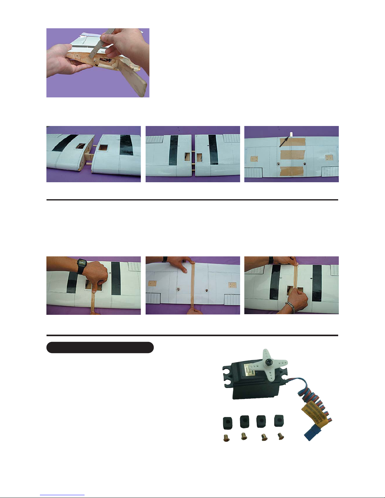
5.1 Prepare the servos by fitting the rubber
grommets & ferrules supplied with your radio
Wing dowel into the leading
edge with 30 minute epoxy
Use low tack masking tape to hold the two panels tightly together until the glue cures.
Stage 4 Once the glue has cured completely (allow several hours at least), the tape can be removed
from the wing panels. To avoid lifting the covering , peel the masking tape back on itself when
you removing it. Do not pull the tape up, peel it back horizontally against itself. To cover the
joint in the wings, a length of wing joint tape is supplied. Starting from the upperside, stick the tape centrally over
the joint ensuring that it is pressed down firmly as you work around the wing. Wrap the tape all the way around the
wing joint in one piece, starting and finishing at the flap servo cutout in the top of the wing.
Stage 6
8
Carefully remove the white cover plates from the aileron
servo cavities. Ensure you know which cover plate is for the
right wing and which is for the left. Remove the white cover
plates and retain the mounting screws. Notice that there are
wooden servo rails pre-installed into each servo cavity end.
Locate the wiring harness tubes that are protruding slightly
into each aileron servo cavity. The tube can be moved slight-
ly at this point. Check out the other end of each tube for a
clean position and then using C/A glue secure the wiring har-
ness tubes at the aileron servo cavity ( See illustration 18.1
and 18.2 for typical installation.
Install a servo in each aileron servo cavity and connect the
servo wire to the servo extension wires and run the extension
wires through wiring harness tubes to the centre of the wing
Install the aileron control horns
Aileron servo cavity
5.1 Aileron servo location
5.2 Aileron servo mount 5.2 Screw servo in position 5.3 Install aileron control horn
Step 1 Consult your radio instruction manual and center each aileron servos by plugging it into the aileron channel
in the receiver. Turn on the transmitter and then the receiver. Center the aileron trim lever on the transmitter.
Remove the servo arm mounting screw and the servo arm.
Step 2 Mount the servo arm back on the servo. Position the arm so that the arm is perpendicular to the surface of
the wing. Screw the arm into place with the servo arm mounting screw supplied with the servo.
Locate the two aileron control rods in the hardware bag. Ensure the clevises are screwed well onto the threaded
portion of the rod. Rotate and tug aggressively on the clevises and ensure that they are not loose on the rods.
Tape the ailerons into their neutral position so that they are even with the trailing edge of the wing and not pointing
either up or down.
Step 3 Ensure that the aileron control horns are screwed onto the threaded aileron control horn bolts and that both
control horns are in approximately the same place on their respective bolts.
Step 4 Connect the aileron servo rods to the aileron control horns. If one of the two clevises on each rod has a
metal pin or screw, attach that clevis to the servo output arm.
Step 5 Connect the other clevis to the servo output arm
Step 6 Remove the masking tape holding the ailerons.
Step 7 In the case of computer radios, couple the servos together by connecting them to the appropiate receiver
channel . In the case of analog radios couple the servos together using a Y harness
Step 8 Turn on your radio and activate the ailerons, using the aileron stick and ensure that a smooth full motion
can be achieved.
Step 9 With the wing top side up and viewed from the back, ensure that moving the transmitter aileron stick to the
left raises the left aileron and lowers the right aileron. Movement of the stick to the left will roll the aircraft to the left.
(Counterclockwise roll of the wing when viewed from the back ).
Step 10 With the wing top side up and viewed from the back, ensure that moving the transmitter aileron stick to the
right raises the right aileron and lowers the left aileron. Movement of the stick to the right will roll the aircraft to the
right.
Stage 7
9
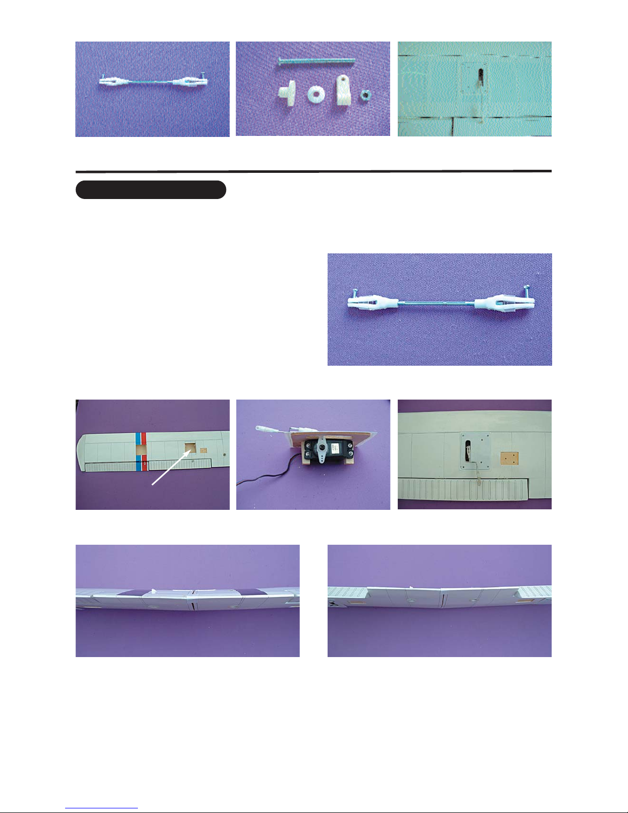
6.1 Aileron control rod assembly 6.2 Aileron control horn assembly 6.3 Aileron control installed
FITTING FLAP SERVOS
To install the flap servos into the wings you will need
the following items :
- Servos
- Servo mounting screws and grommets as supplied
with the servo.
- Servo control arm as supplied with the servo.
- Flap control rod assemblies
- Low tack masking tape.
7.1 Flap control rod assemblies
7.3 Flap servo position 7.4 Final flap instalation
7.5 Flap up 7.6 Flap down
Flap servo location
7.2 Flap servo in each wing
Stage 8
Stage 9
Stage 10
10
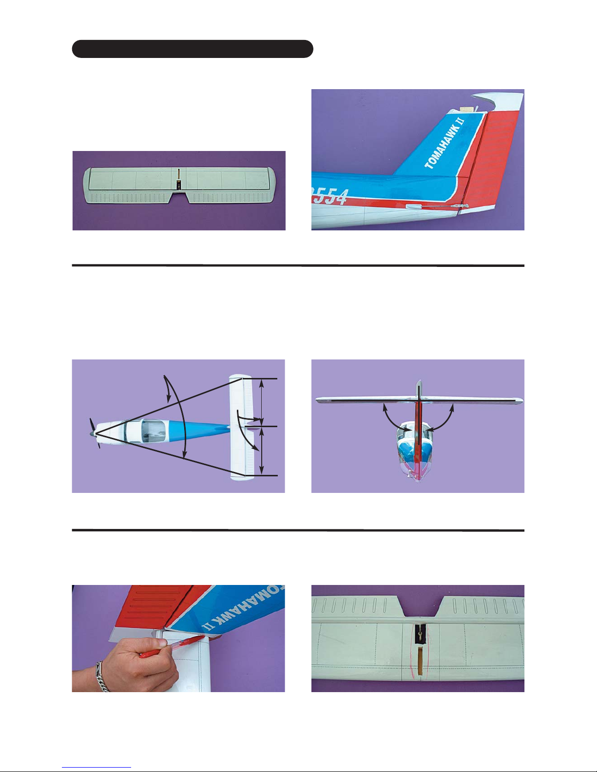
FITTING THE HORZONTAL STABILIZER
To install the stabilizers to the fuselage you will need.
- Fuselage (with pre-installed vertical stabilizer and
rudder)
- Horizontal stabilizer with pre-installed elevator
Horizontal stabilizer with pre-installed elevator The completed fuselage with pre-installed vertical
stabilizer and rudder.
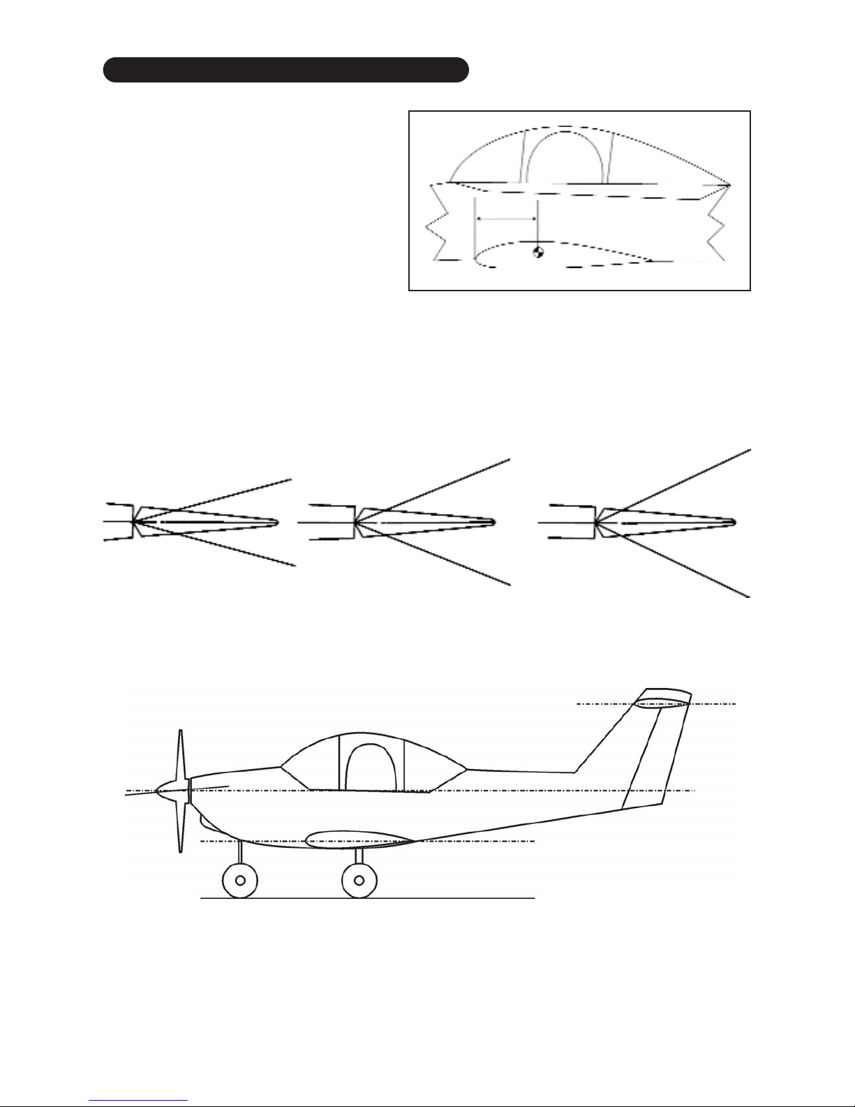
Check the fit of the horizontal stabilizer in its slot. The horizontal stabilizer should be set for
0 degrees incidence. Please see the incidence diagram on page 19 and sand the seating
area on the top of the vertical stabilizer order to ensure 0 degrees incidence on the horizontal
stabilizer. Work in small steps and check frequently. Use an incidence meter if possible.
Once you have the incidence correct, make sure the horizontal stabilizer is square and cen-
tred to the fuellage as show in the diagram below. DO NOT GLUE ANYTHING YET.
Equal
distance
Equal distance
900
9.1 Trial fit the horizontal stabilizer in its slot
With the horizontal stabilizer correctly aligned, mark the shape of the fuselage on
the bottom of the tailplane using a water solublenon-permanent felt-tip pen as
shown here.
10.1 Mark the bottom of the horizontal stabilizer 10.2 Marked lines on horizontal stabilizer
9.2 90 degree angle between the horizontal and
vertical stabilizer

Stage 11
Stage 12
Stage 13
11
Now remove the horizontal stabilizer and, using a sharp knife CAREFULLY cut 2mm inside the marked lines and
remove the covering on the bottom of the tail as shown. Make sure you only cut the film and not the wood, oth-
erwise the horizontal stabilizer wiil be severely weakened.
If you do cut into the wood, seal and fill the cut with CA and test for strength before proceeding further.
11.2 Covering removed from bottom surface11.1 Marked lines on horizontal stabilizer
Now apply sufifciant 30 minute epoxy to the bottom of
the horizontal stabilizer and to the top of the vertical
stabilizer as shown. Use 30 minute epoxy to ensure a
strong bond and give yourself plenty of working time.
Insert the horizontal stabilizer in its slot in the top of the
vertical stab and re-check the alignment as in Stage 9.
Excess epoxy should be cleaned off with a rag or tissue
before it cures. Please review the instrations and
instructions carefully before attaching the horizontal sta-
bilizer. (Check page 21 for incidence set-up)
12.1 Apply plenty of epoxy 12.2 Apply of epoxy to the top of
vertical stabilizer
12.3 Vertical hinge line must line
up with horizontal hinge line
Don’t put epoxy here
Don’t put epoxy here
Vertical hinge line
Horizontal
hinge line
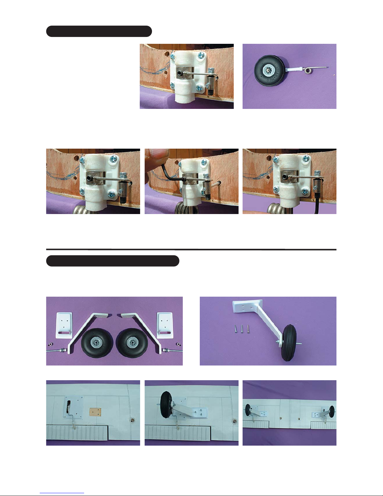
FITTING THE LANDING GEAR
To install the landing gear you will need the folowing parts.
- 2 fiberglass main landing gear (1 left and 1 right)
- 2 axle assembly
- 2 main landing gear cover
- 3 wheels ( 75mm x 25mm)
- 6 sheet metal screws 5 x 35 mm
- 1 nose gear assembly
Nose gear assembly
Nose gear
with strut
Wheel collar
Steering arm
75 mm
wheel
Stage 14
Stage 15
12
FITTING THE MAIN LANDING GEAR
15.1 Main landing gear components
FITTING THE NOSE GEAR
Fit the nose gear steering arm
onto the EZ connector on the
steering arm pushrod as a per
illustration 14.1. Note which way
round the arm should be orientat-
ed. Now slide the steering arm
into the middle of the pre-fitted
nylon nose gear bearing.
14.1 Insert the EZ connector
threaded shaft through the steer-
ing arm, secure with a nut and
place the arm into the nylon nose
gear bearing
14.2 Nose gear with wheel
14.3 Holding the nosegear steer-
ing arm in place, slide the
nosegear into the nylon mount,
passing through the steering arm.
14.5 Loosen the EZ connector
bolt to adjust the movement of the
nosegear
14.4 Now tighten the nosegear
steering arm
15.2 Main landing gear components
Turn over the wing to locate the 3 pre-drilled main
landing gear mounting holes in each side of the wing
15.3 Main landing gear location 15.4 Main landing gear in place 15.5 Main landing gear and land-
ing gear covers in place

Stage 16
Stage 17
13
FITTING THE FUEL TANK
To assemble the fuel tank you will need the following
items:
- The fuel tank and fuel stopper assembly (supplied)
- The clunk (supplied)
- About 7” (20 cm) of medium ID silicone fuel line (DUB
197 or similar)
- Cross head Philips screw driver
16.1 Use 100 mm (4 in) for fuel line
and 50 mm (2 in) for pressure line
16.2 Illustration of fuel line posi-
tioning inside the tank
16.3 Fuel tank installed on the
power module
100 mm (4 in) for fuel line
50 mm (2 in) for pressure line
fuel line
pressure line fuel line
pressure line
INSTALLING THE ENGINE
The engine and the fuel tank are installed onto the
power module. First remove the power module from
the fuselage by removing the 4 nuts & washers
power module
17.3 Aluminum engine mount17.2 Power module assembly 17.4 VMAX .46 2 cycle engine rec-
ommended
fuel tank
mouting dowels
Engine horizontal thrust line approximately
40 mm 1.56 in) from top of fuselage
17.1 Power module
17.6 Engine and fuel tank posi-
tioned on the power module
17.5 Fitting the engine to the
engine mount
17.7 Engine and engine mount
recommentded orientation

Stage 18
Stage 19
14
17.9 Pitts type muffler suitable for
VMAX .46
17.8 Fuel line and pressure line
hook up to the engine
17.10 Fuselage without power
module
Fuel line
Pressure line
Pressure line
power module mount bolts
17.11 Power module mounted to
the fuselage
17.12 Power module mounted to
the fuselage (side view)
17.13 See cowl installation tips on
page 19
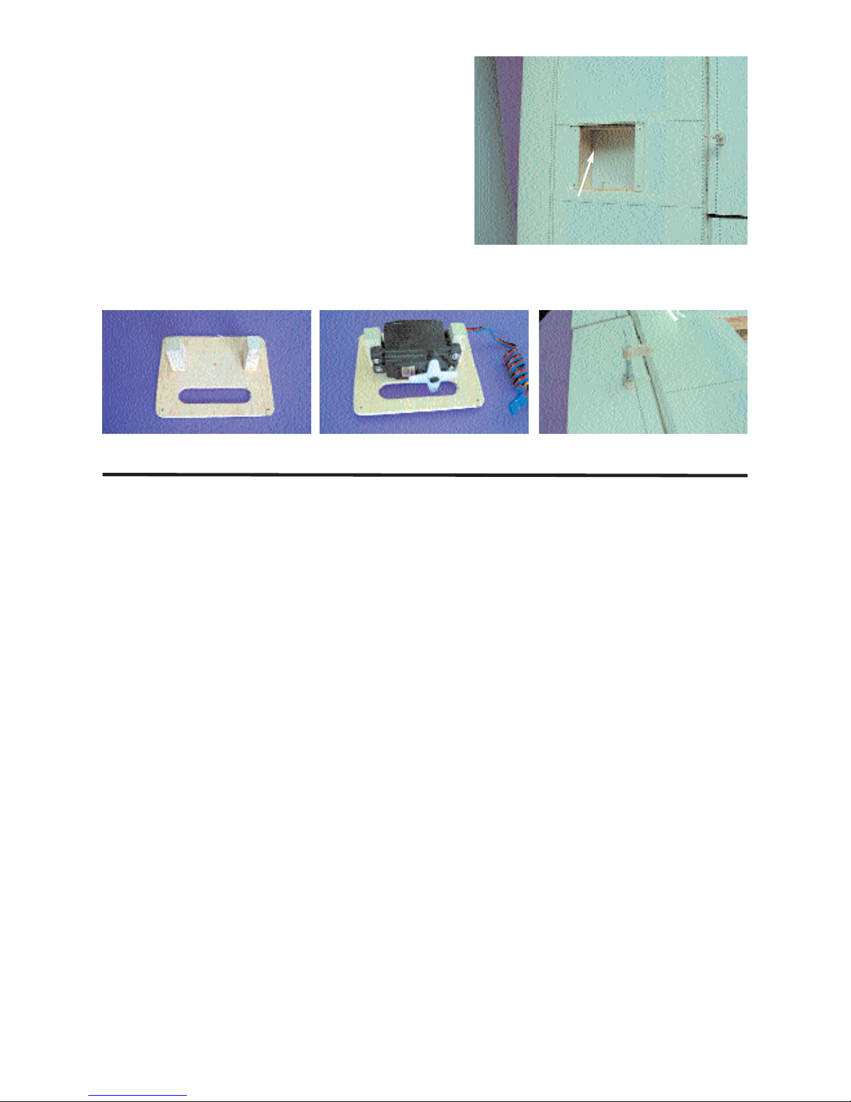
FITTING ELEVATOR AND RUDDER CONTROL HORN
The elevator control horn
is pre-installed by the fac-
tory For rudder, pierce the
covering over the pre-
drilled hole for the control
horn installation as shown 18.1 Control horn assembly 18.2 Typical control horn mounted to
the surface control
18.3 Pre-installed elevator control horn 18.4 Rudder control horn location as shown
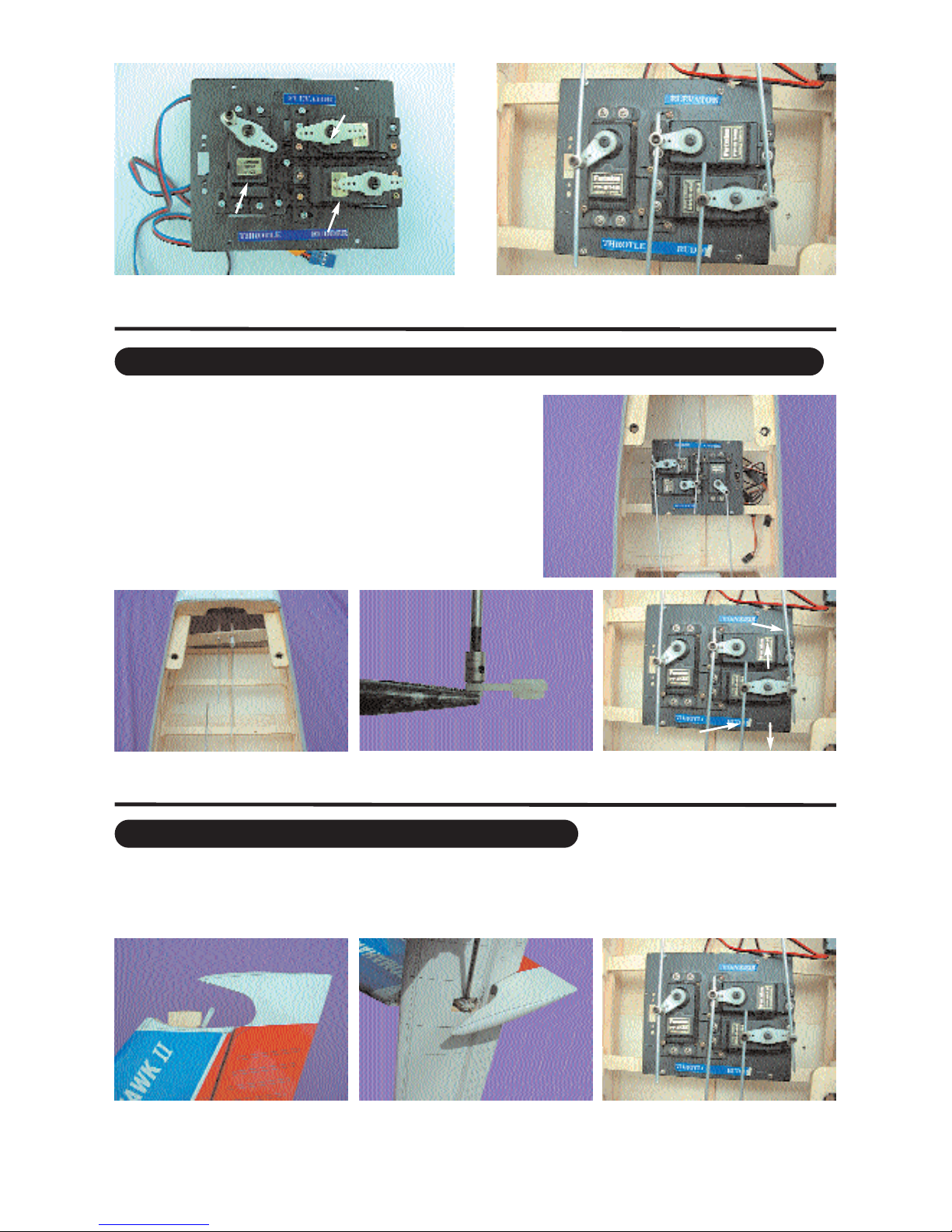
INSTALLING THE SERVOS
Install the rubber servo grommets and brass ferrules supplied with your radio
equipment. The three servos that control the elevator, rudder and throttle are
Installed in the servo tray mounted in the fuselage. Remove the servo tray
from the fuselage. Mount the servos to the servo tray as shown. 19.1 Universal servo mount
Stage 20
Stage 21
15
19.2 Note the orientation and positions of the
three servos in the servo tray
Throttle servo
Elevator servo
Rudder servo
19.3 Throttle, elevator and rudder servos connect-
ed to their pushrods
20.1 Consult the picture showing how the throttle, rudder,
nose gear steering and elevator servos are positioned
and connected to the pushrods.
CONNECTING THE PUSHRODS TO THE THROTTLE, RUDDER AND ELEVATOR SERVOS
20.2 Pre-installed elevator and
rudder pushrods
20.3 Install EZ connector to the
servo arm
20.4 Connecting the nose steering
pushrods to the rudder control
Connect the elevator servo to the receiver and turn on your transmitter. Confirm that the
neutral positions of the elevator servo are sustained as per illustration 20.4
21.1 Pre-installed elevator
pushrod
21.2 Connecting the elevator
pushrods to the control horn
21.3
Connecting the elevator
pushrod to the elevator servo arm
CONNECTING THE PUSHRODS TO THE ELEVATOR
Rudder pushrod
Steering
pushrods
Front
back
Stage 22
Stage 23
Stage 24
16
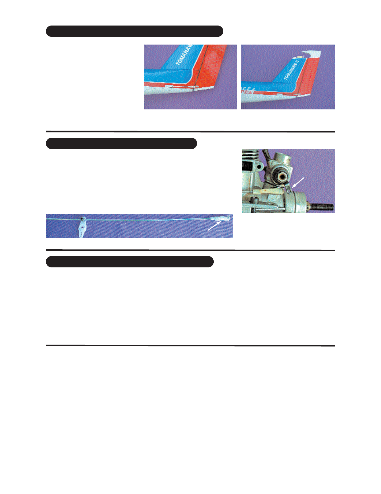
CONNECTING THE THROTTLE CONTROL
Connect the clevis to the engine throttle arm at roughly half throttle. Look
into the throat of the engine carburetor as you rotage the throttle arm and
select a position where the throttle opening is about hafl what it is when
fully open.
25.1 Throttle control rod
Connected to the engine throttle arm
engine
throttle
arm
25.2 Throttle control rod con-
nected to the engine throttle arm
CONNECTING THE PUSHRODS TO THE RUDDER
Connect the rudder servo to the
receiver and turn on your transmit-
ter. Confirm that the neutral posi-
tions of the rudder servo are sus-
tained as per illustration 20.4 22.1 Rudder control horn installed
and shown in position
22.2 Connecting the rudder
pushrod to the rudder control
horn
Adjust the deflection of the control surfaces to match the specifications on page 19
You can reduce the amount of throw by doing either or both of the following:
From the servo end, move the clevis or EZ connector to a hole in the servo arm that is closer to the servo output
shaft.
From the control horn end, move the horn out further on the threaded bolts. Always confirm that the horn is still thor-
oughly engaged with the threaded bolt after you have adjusted it.
ADJUST CONTROL SURFACE THROW LIMITS.
27.1 Consult your radio manual for instructions
about hooking up your receiver battery, receiver and switch harness.
27.2 Wrap the battery pack securely in foam suitable for RC equipment and wrap the foam insulated pack in a plas-
tic bag or cling wrap.
27.3 Thread the battery pack connector back through from beneath the fuel tank to the radio compartment by pass-
ing the battery connector through an opening beside or beneath the fuel tank.
27.4 Connect the battery connector to your radio system according to the radio manual.
17
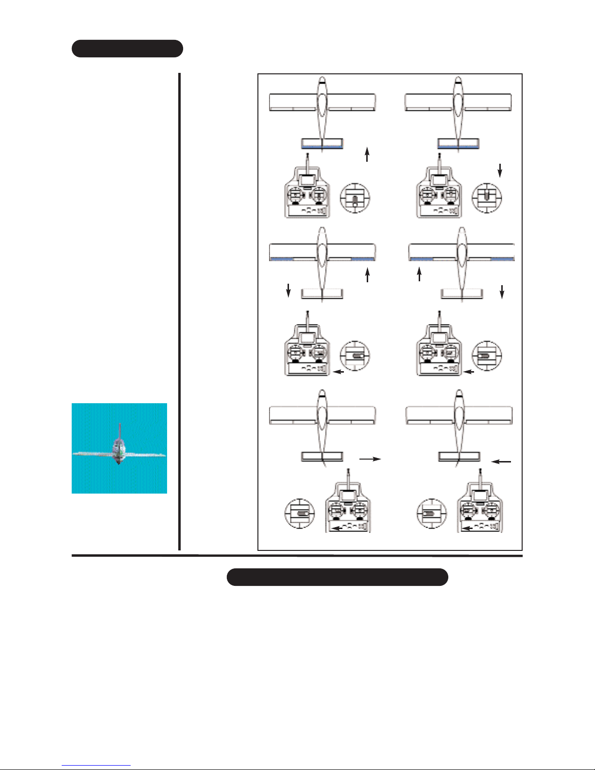
FINAL R/C SET-UP
Before starting the final
set-up of the model,
switch on the radio and
ensure that all trims are
in their neutral posi-
tions. Check that the
ailerons, elevator and
rudder are centred. If
any adjustments are
needed, do these by
uncoupling the relevant
clevis and turning it
clockwise to shorten
the linkage or couter -
clockwise to lenthen it.
Only when each control
surface has been cen-
tred mechanically in
this way should you
begin adjusting the sur-
face movement (or
throw)
Now confirm
that the con-
trol surfaces
are moving
in the correct
direction.
Use the
servo revers-
ing swiches
on your
transmitter to
reverse the
direction of a
servo if nec-
essary. The
most popular
transmitter
mode (with
the throttle
on the left,
with the
ailerons and
elevator on
the right) is
shown here.
Stage 25
ELEVATOR
UP
ELEVATOR
DOWN
AILERON
UP
AILERON
DOWN
AILERON
DOWN
AILERON
UP
RUDDER
RIGHT RUDDER
LEFT
Stage 26
INSTALLING THE RECEIVER BATTERY
Stage 27

28.1 Consult your radio manual for instructions about hooking up your receiver.
28.2 Plan where you are going to put the receiver with consideration for routing the antenna safely.
28.3 Wrap the receiver securely in foam suitable for RC equipment and wrap the foam insulated receiver in a plas-
tic bag or cling wrap.
28.4 Generally in the absence of specific instructions from the radio manufacturer, it is recommended that the
receiver should be placed where it is least likely to have impact during a crash. Keep the battery pack and other
heavy loose items ahead of the receiver.
31.1 Consult your radio manual for instructions about testing and operating your radio system.
31.2 Pay particular attention to charging your radio system batteries and range testing the system before and after
each flight.
Check that all controls are working correctly before and after each flight.
The CG for your TOMAHAWK is located at 65 mm (2.56 inch ) back from the leading edge of the wing when the
wing has been attached to the fuselage.
For the initial flight, the CG should be located at 2.56” (65mm) back from the leading edge of the wing when
the wing has been attached to the fuselage.
The CG is measured with the engine, radio gear and all other components installed but WITH NO FUEL IN THE
TANK.
Set up the CG as it will be when you fly it BUT WITH NO FUEL IN THE TANK.
It is very important to have the CG correct. Flying your model with the CG wrong will likely lead to loss of control
and a crash.
If you discover that after you have assembled your model and installed your radio and engine that the CG is incor-
rect you must bring the CG to the correct location by doing the following BEFORE FLYING :
- Move the battery pack fore or aft.
- Move other components fore or aft.
- Change engine to a lighter or heavier model.
- Add weight to the nose or tail. If adding it to the nose, try to make it useful by going to a heavier duty engine
or adding a spinner with a heavy metal backing plate. As a last resort, add stick on “dead” weight where appro-
priate.
18
Stage 28 INSTALLING THE RECEIVER
Stage 29 COMFIRM RADIO OPERATION
Stage 30 BALANCING THE AIRCRAFT.
Stage 31 CONFIRM MECHANICAL INTEGRITY
31.1 Once you have confirmed that the CG is correct, you should do a thorough review of the entire model before
your first flight. Check everything twice! Every hook up, every coupling, everything! Do it twice!!
31.2 Before your first flight, have an experienced flyer review your work. Do not fly your model until it has been
checked out by a third party who knows how to fly and how to set up a model aircraft
31.3 Once you have completed your first flight, get in the habit of checking your model over before and after each
flight! Don’t fly if you find something that is not right!
Stage 32
High rate Low rate
ELEVATOR 1/3 “ ( 10mm) up 1/5” ( 6mm) up
1/3 “ ( 10mm) down 1/5” ( 6mm) down
RUDDER 1 “ (25mm) right 5/8” (16mm) right
1” (25mm) left 5/8” (16mm) left
AILERON 1/2” (16mm) up 1/3” (10mm) up
1/2” (16mm) down 1/3” (10mm) down.
Note: If your radio does not have dual rates, then set the control surfaces to the low rates.
19
65 mm
2.56”
Elevator Aileron Rudder
5/8”
16mm
5/8”
16mm
1/3”
10mm
1/3”
10mm
1/5”
6mm
1/5”
6mm
CG
NOTE : The throws are measured at the
widest part of the elevator, rudder and aileron.
Adjust the position of the pushrods at the con-
trol/servo horns to control the amount of
throw. You may also use the ATV’s if your
transmitter has them but the mechanical link-
ages should still be set so that the ATV’s are
near 100% for best servo resolution.
CG, INCIDENCE & THROW SPECIFICATIONS
engine .0. To 2
degrees down thrust
Horizontal stabilizer
incidence 0 degrees
Wing - incidence 0 degrees

Cowl Installation Tips
You may have your own method to adapt and install the cowl to fit your model, your choice of engine and your
choice of engine orientation... here is one method to add to your bag of tricks!
1) Use a sheet of card stock or better yet a sheet of clear thin plastic like that used to protect documents. Using
a clear sheet is strongly recommended.
2) Wrap the sheet as close as possible around the cowl, preferably tapered slightly towards the front. Tape the
sheet so that it stays in a cylindrical shape approximating the cowl. Trim the aft edge of the sheet to approxi-
mately match the aft edge of the cowl. Trim the front edge of the sheet to approximately match the front edge
of the cowl. Put a couple of registration marks on the dummy cowl and real cowl so that you can apply the
dummy cowl over the real cowl in a similar manner again. Now remove the sheet from the cowl, in one piece if
possible. If it is not possible to remove the sheet in one piece, use a felt tip pen to mark the sheet so that you
can untape it, then remove it from the cowl and then retape it back together into the cylindrical approximation
of the cowl. In effect you now have a rough dummy cowl that can be used to make a template to help you later
fit the real cowl.
3) Now install the engine on the engine mounts and measure the distance from the back of the engine mount
to the front of the thrust washer
4) Draw a vertical line on the forward face of the firewall so that it is in the middle of the firewall and at right
angles to the horizontal line drawn on the firewall at the factory. If there is no horizontal line on the firewall, check
the set up specs for this model and draw the horizontal thrustline at the location indicated.
5) Install the real cowl on the model and slide the cowl back until the distance from the firewall to the cowl nose
ring hole is similar to the distance measured in step 4 AND that at least 1/4 in (6mm) of the edge of the cowl
overlaps the front of the fuselage. Carefully square the cowl with respect to the fuselage so that it looks aligned
from the top, sides, bottom and front. Look through the cowl nose ring hole and try to align the centre of the cowl
nose ring hole with the intersection of the vertical and horizontal thrust lines onthe front face of the power mod-
ule. Measure the distance from the forward face of the firewall to the nose ring hole in the cowl. Use low tack
masking tape to hold the cowl loosely in place while you adjust it. Once you have the cowl squared up and set
where you want if fore and aft, apply a line of low tack masking tape around the circumference of the fuselage
so that the forward edge of the masking tape just butts up against the aft edge of the cowl.
6) Remove the real cowl from the model.
7) Install your engine mount and engine and muffer onto the model. Orient the engine to the position you
want...i.e upright, rotated 45 degrees inverted etc. Make sure the muffer and the carburetor are installed. When
selecting which orientation you want for the engine you need to keep in mind operational considerations... the
muffer for examine must clear the sides of the fuselage by at least 5mm and carburetor throttle arm must be
connectable to the thottle control rod running forward through the firewall from the throttle servo. Lastly, the fuel
lines coming through the stopper hole in the run to the muffer pressure tap and the carburetor fuel nipple.
8) Once you have positioned your engine mount and engine, secure them to the forward firewall of the power
module and install the forward firewall onto the model using the four mounting studs, nuts and washers. We rec-
ommend setting the forward firewall at zero degrees offset thrust for now. Use the same number of washers and
nuts on all four studs. You can adjust a bit of right or down thrust into the firewall later if required.
9) Remove the muffer and the carburetor from the engine. Set the muffer and the carburetor aside. Be careful
not to lose any parts.
10) Now try to fit the dummy cowl on to the fuselage. You will find that the dummy cowl will likely be obstructed
by the engine as you try to install it. Assuming you are using the recommended clear sheet material you will be
able to see where the obstruction begins. Using a left tip marker mark the area onthe dummy cowl to fit over
the engine.
11) Remove the dummy cowl and cut away the area that you have marked. We suggest cutting away less than
you think at first and expanding the cut out area in small incremental steps. Repeat this trial and error process
until the dummy cowl can be installed with rear edge of the dummy cowl aligned with the forward edge of the
line of tape onthe fuselage. You will have to repeat this process numerous times and we recommend working
in small steps. If you overdue a cut, use masking tape to fill in the over cut area.
12) Once you can install the dummy cowl over the engine, remove the dummy cowl and install the the carbu-
retor back on the engine.
20
Table of contents
Other Piper Toy manuals


