JR vibe e12 sg fbl Owner's manual

CHOICE
SUPPLEMENTAL MANUAL
EDITION
The photo depicts an assembled model
Assembly steps
Step1
VIBE SG E12 FBL Assembly manual
Ito Edition Supplemental manual
1-1
1-2 〜 1-6
1-7 〜 1-9 deleted
Step2
2-1 〜 2-3
2-4、2-5
2-6 〜 2-8
2-9 deleted
2-10 , 2-11
2-12、2-13
Step3
3-1
3-2
3-3
3-4 〜 3-8
PITCH JIG ASSEMBLY
Step4
4-1 , 4-4
4-5
4-6
4-7、4-8
4-9
4-10
4-11
4-12
Step5 5-1、5-2
5-3、5-4
Step6 6-1
6-2
Specications
Length 1,359mm Height 406mm Width 182mm
Main rotor Dia. ※1 1,580mm Tail rotor Dia. 288mm Gross weight ※2 3,600g 〜
Gear ratio T9 10.3 : 1 : 4.65 Control System 120 ° CCPM
Tail drive system : Shaft drive
※ 1 with 710mm main blades
※ 2 not including main blades or battery
PLEASE READ THIS FIRST

P.2
Red(×2)
Green
Green
● Secure the Pinion Gear and Inner race of the support bearing using thread lock.
Also secure the Pinion Nut to the Pinion Gear using thread lock.
Pinion bearing block
Pinion nut M9
Temporarily tighten the setscrew M4 ×
4 onto the 'at' on the motor shaft.
Motor mount
Brushless motor
(Sold separately)
Button head bolt M4 × 8 ( × 2)
Complete Assembly
Helical pinion gear T9
Special washer M4 ( × 2)
1-1 MOTOR MOUNT AND PINION GEAR INSTALLATION
DANGER
DANGER
※ T10 and T11 are also available as
optional parts.
● If you are using a Scorpion HK-4525-520KV, the 'flat'
length must be extended upward by 2mm.
※ If there is no 'at', please le one as shown above.
※ Temporary tighten the setscrew M4 × 4 so as the height
of the pinion gear can still be adjusted when the assembly
is tted to the frame.
Note the proper direction
Top
14mm

P.3
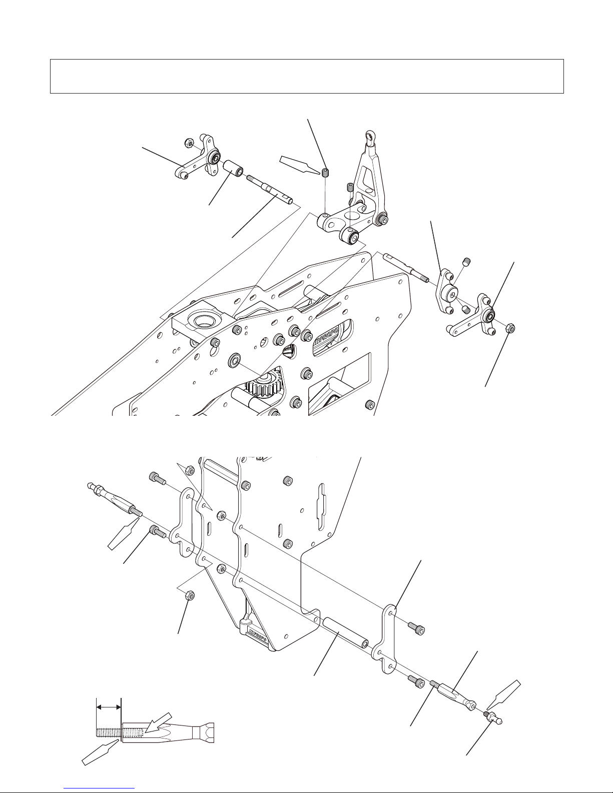
An adjustment hole for the alignment pin has been added to the T-arm.
There is no change to the assembly method.
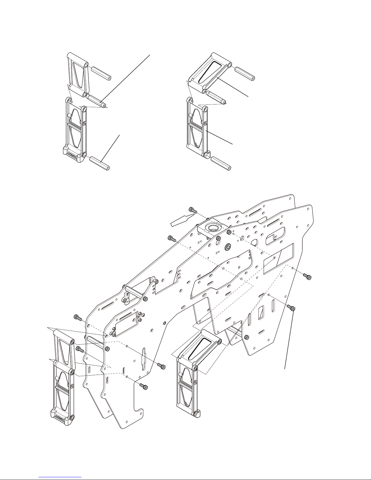
1-4 T-ARM AND ELEVATOR ARM ASSEMBLY
1-5 SWASH CONTROL ARM ASSEMBLY
1-6 DRIVE GEAR ASSEMBLY
1-8 CARBON TOP TRAY ASSEMBLY
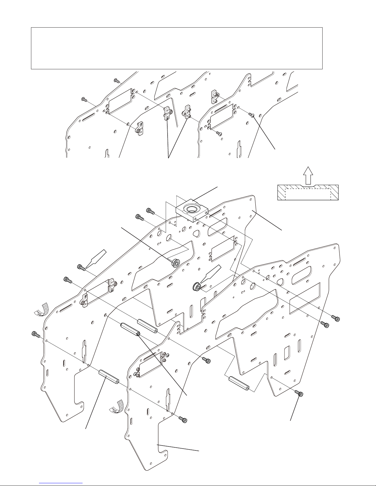
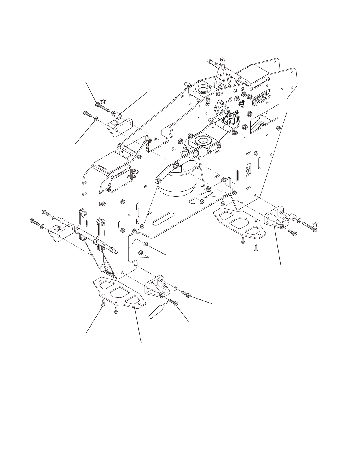
1-7 CARBON FRAME SUPPORT PLATE ASSEMBLY
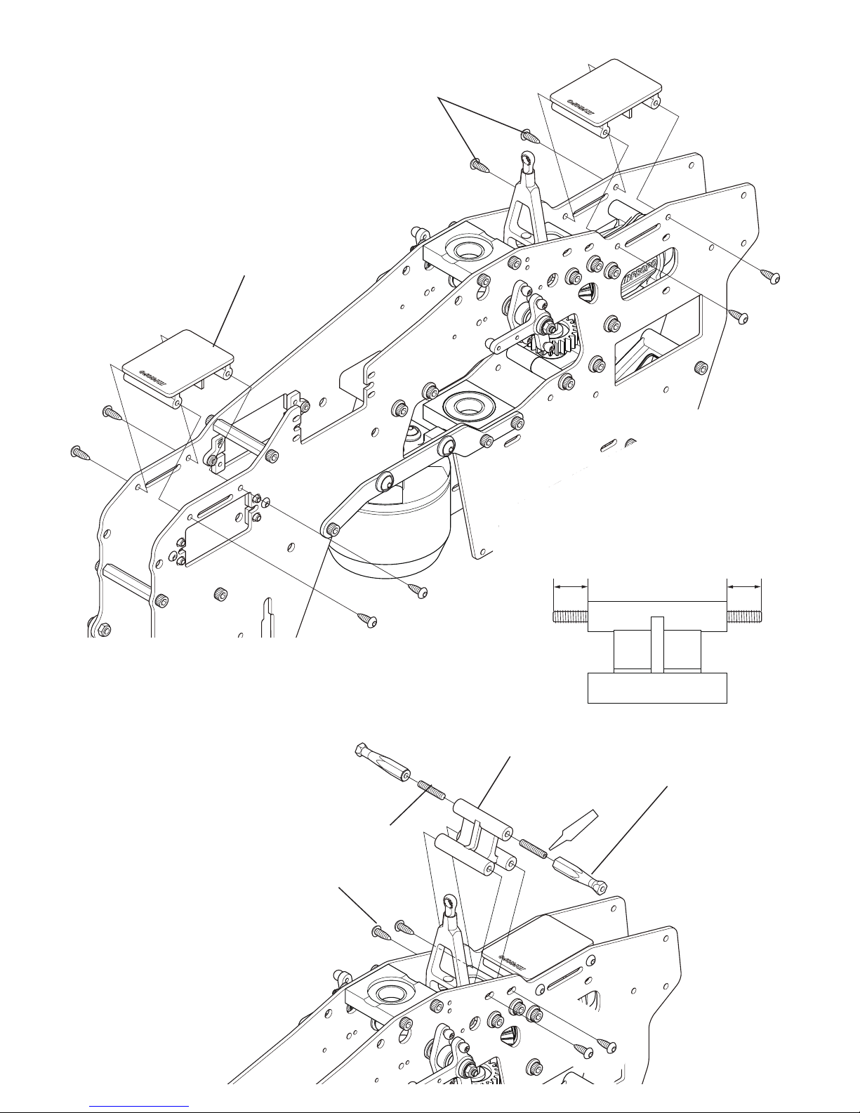
1-9 FRONT TRAY OR BODY MOUNT PLATE ASSEMBLY
An adjustment hole for the alignment pin has been added to the Swash control base.
There is no change to the assembly method.
The drive gear thickness has been increased.
The side marked "T93" should face up when assembled.
This step has been deleted.
The body catch will be assembled in a later step.

P.4
A+B (×2)
Red (×10)
JRPROPO
HeliDivision
DESIGNEDBY CHECKEDBY
MATERIAL COLOR
S.KUNII
A2011S ブラック
REV№ REVISIONNOTE
28
32- 0.03
0
A
A
4
8
20 0.03
4
4-M3X0.5TAP(D=7)
R3
R3
1
Ø 22
6
断面図A-A
● The main frame has a Left and Right. Refer to the gure and install the servo mount plates.
● Use epoxy to bond the Flanged bearing F4 × 10 × 4 to the frame. Install it from the inside of
the main frame. Do not let adhesive get into the race of the bearings.
● Carefully note the orientation of the bearing block.
Note the proper orientation
Top
Carbon main frame L
Carbon main frame R
Flanged bearing
F4 × 10 × 4 ( × 2)
Bearing block w/bearing
Socket head bolt M3 × 8 ( × 10)
Button head bolt M2.5× 6 (× 4)
Cross member L32 ( × 3)
Servo mount plate ( × 4)
Cross member w/step L32
2-1 CARBON MAIN FRAME ASSEMBLY

P.5
Red(×8)
Socket head bolt M3 × 8 ( × 8)
Beam cross member CA (× 2)
Cross member L32 (round end) ( × 2)
Cross member L32 (× 4)
Beam cross member CB ( × 2)
2-2 BEAM CROSS MEMBER C INSTALLATION

P.6
Red(×6)
JRPROPO
HeliDivision
DESIGNEDBY CHECKEDBY
MATERIAL COLOR
S.KUNII
A2011S ブラック
REV№ REVISIONNOTE
28
32- 0.03
0
A
A
4
8
20 0.03
4
4-M3X0.5TAP(D=7)
R3
R3
1
Ø 22
6
断面図A-A
2-3 BEARING BLOCK W/BEARING INSTALLATION
● Carefully note the orientation of the bearing block.
Note the proper orientation
Down
Bearing block w/bearing
Socket head bolt M3 × 10 ( × 6)
Carbon twist support ( × 2)

P.7
Red(×4)
Red (×2)
Red(×2)
8mm
Red
● Secure the Setscrews onto the D-cut recesses of the 120 ゜ CCPM pivot pins.
●
Tighten the nylon lock nut M3 rst and then tighten the setscrew M4 × 4 securing the elevator control arm.
Lever spacer 120°
Cross member L36
Nylon lock nut M3 ( × 2)
Setscrew depth
Hex hole this side
T-arm L
T-arm R
Setscrew M3 × 15 ( × 2)
Elevator arm
Setscrew M4 × 4 ( × 4)
120° CCPM pivot pin ( × 2)
※ This helicopter is designed for 120 ゜ CCPM only. Parts for 140 ゜ CCPM are not included.
※ This product does not include parts for the Front tray or Top tray.
2-6 SWASH CONTROL ARM AND T-ARM INSTALLATION
2-7 CARBON BODY MOUNT PLATE INSTALLATION
Carbon body mount plate ( × 2)
Socket head bolt
M3 × 8 ( × 4)
Body catch head L2 ( × 2)
Body catch L30 ( × 2)
Nylon lock nut M3 (× 4)

P.8
Red (×2)
Hex tapping screw M3 × 8 ( × 8)
Gyro mount ( × 2)
Body catch L30 ( × 2)
Hex tapping screw M3 × 8 ( × 4)
Plastic canopy post mount
(sold as Cooling fan cover stay bracket)
Setscrew M3 × 15 ( × 2)
8mm8mm
2-8 GYRO MOUNT AND BODY CATCH INSTALLATION

P.9
Red(×2)
Hex tapping screw M3 × 8 ( × 4)
Flat washer M3 ( × 8)
Nylon lock nut M3 ( × 4)
Socket head bolt M3 × 12 ( × 2)
Socket head bolt M3 × 10 ( × 4)
Socket head bolt M3 × 22 ( × 2)
Spacer B ( × 2)
Carbon brace adapter plate ( × 2)
Landing strut adapter ( × 4)
2-9 CROSS MEMBER INSTALLATION
2-12 LANDING STRUT ADAPTER INSTALLATION
This step has been deleted.

P.10
CA/G (×4)
2-13 LANDING GEAR INSTALLATION
Socket head bolt M3 × 18( × 4)
Nylon lock nut M3 ( × 4)
Flat washer M3 ( × 8)
Setscrew M3 × 4 ( × 4)
※ Do not over tighten.
Landing skid cap ( × 4)
Landing skid (black) ( × 2)
Low prole landing strut ver.2 ( × 2)

P.11
Red(×3)
Red (×3)
Red (×4 )
● Do not over tighten the ball arms.
Ball arm L9 ( × 3)
Control ball L5.5 ( × 4)
Swash plate 90 (V2)
Setscrew 3 × 3 ( × 3)
● Adjust the swashplate by tightening the setscrew M3 × 3 to
minimize unsteadiness (slop) of the upper plate and lower plate of
swashplate. If there is such unsteadiness, tighten the setscrew M3
× 3 as shown in the gure to the right and adjust them to minimize
the unsteadiness. Be sure to tighten them gradually. If you tighten
them too much, the lower plate may be deformed or may not rotate
smoothly (if you do not feel unsteadiness, you do not have to use
these screws). Note that the unsteadiness of swashplate can not
be completely eliminated. Do not tighten the screws too much.
3-2 SWASH PLATE ASSEMBLY
3-3 MAIN BLADE HOLDER ASSEMBLY
The Main blade holder shape has been changed.
There is no change to the assembly method.
The main shaft has been changed to a hardened main shaft.
There is no change to the assembly method.
3-1 MAIN GEAR INSTALLATION

P.12
Red(×2)
☆
Red
※ Temporarily tighten this bolt so as
the assembly can still slide on the
main shaft. It will be tightened later.
3-4 FBL CENTER HUB ASSEMBLY
3-5 FBL WASHOUT ARM ASSEMBLY INSTALLATION
Head button
● A special socket head bolt is used
to secure the rotor head. Check it
regularly and replace as necessary.
FBL center hub (90) V2
Socket head bolt M3 × 8
Tighten firmly after adjusting rotor pitch
using the FBL pitch jig.
Special socket head bolt M4 × 26
Socket head bolt M2.6 × 8 ( × 2)
Upper plate lock base
Nylon lock nut M4 (t3.8)
FBL washout arm assembly ( × 2)
Socket head bolt M3 × 18 ( × 2)

P.13
Brg グリス
(×2)
GreaseUp
Green (×2)
3-7 MAIN BLADE HOLDER INSTALLATION
3-6 SPINDLE SHAFT INSTALLATION
O-ring 8.8 × 12.6 × 1.9 ( × 2)
Spindle shaft (90)
● Sparingly apply No.61597 JR Thrust bearing grease onto the thrust bearings.
● Please replace the button head bolts each time they are removed for maintenance, etc.
Spindle shaft washer M6 ( × 2)
Note direction
Center hub sideRotor blade side
Thrust bearing 9 × 17 × 5( × 2)
No distinction of front and back
Inner Dia. : large
Inner dia. : small
Thrust washer ( × 2)
Button head bolt M6 × 10 ( × 2)
Grip spacer ( × 2)

P.14
JRPROPO
JRPROPO
JRPROPO
JRPROPO
JRPROPO
JRPROPO
24mm
JRPROPO
※ Make two sets each.
47.5mm
17.5mm
Universal link ( × 8)
Threaded rod M2.3 × 65 ( ∅ 2.5) ( × 2)
Threaded rod M2.3 × 35 ( × 2)
● Please note the proper direction of the universal links.
● Position the Washout base as shown in the gure below. Adjust so the base is 24mm below the head
block and the linkage rods are parallel to the main shaft. Apply a small amount of the thread lock to the
Button head bolt M3 × 18 which was previously temporarily tightened, and now tighten rmly.
3-8 LINKAGES

P.15
Red
Red(×2)
※溝の部分に確実
にはめ込みます。
4-2 TAIL BOOM INSTALLATION
4-3 TAIL GEAR CASE ASSEMBLY
4-5 TAIL PC PLATE AND TAIL SLIDE RING ASSEMBLY
The tail boom now has a JR logo. There is no change to the assembly method.
The Tail gear case and Tail gear case plate L/R shape have been changed.
There is no change to the assembly method.
● Note the proper direction of the PC link. The side with
the four circle marks are toward the direction of the arrow.
Tail PC plate
Tail slide ring assembly
Tail slide ring sleeve
E stopper ring M1.5 ( × 4)
HG tail PC link pin ( × 2)
Setscrew M2 × 2 ( × 2)
Tail PC link ( × 2)
※ Note direction
※ When tightening, please note
this is reverse thread.
NOTE
※ t the E rings into
the slots on the pin

P.16
Brg グリス
(×2)
GreaseUp
Red(×2)
Red (×2)
Red(×2)
4-7 TAIL CENTER HUB ASSEMBLY
●Apply No.61597 JR THRUST BEARING GREASE onto the thrust bearings.
Special socket head bolt M3× 15 (× 2)
Nylon lock nut M3 ( × 2)
Joint ball screw L4 ( × 2)
Carbon tail rotor blades ( × 2)
4-8 TAIL ROTOR BLADE INSTALLATION
Socket head bolt M3 × 8 ( × 2)
Flat washer M3 ( × 2)
Install the
O-rings all the
way onto the
center hub.
HG metal tail blade holder assembly ( × 2)
Thrust bearing 5 × 10 × 4 ( × 2)
Washer 8 × 10 × 0.5 ( × 2)
O-ring 3.5 × 5.5 × 1 ( × 2)
Setscrew M4 × 4 ( × 2)
Tail center hub
Inner dia. : small
No distinction of
front and back
Inner dia. : large

P.17
A+B (×2)
JRPROPO
15mm
約 56mm
15mm
Red (×2)
Universal link ( × 2)
Threaded rod
M2.3 × 25 ( × 2)
Insert the carbon boom 15mm
Assemble size approx. 56mm
Carbon tail control boom L735
Tail control rod end ( × 2)
Tail control rod guide collar (K) ( × 2)
Tail control rod guide (K) ( × 2)
4-10 TAIL CONTROL ROD ASSEMBLY
4-12 TAIL CONTROL ROD INSTALLATION
● Install the Tail control rod guide collar into the slotted
hole of the Tail control rod guide. Then confirm the tail
control rod slides smoothly. If the guide collar does not t
rmly, use some CA glue.
Nylon strap BK ( × 2)
230mm 330mm
● Note the proper direction of the universal links.

P.18
Servo mount plate ( × 2)
Servo holding plate ( × 2)
HEX tapping screw M2.6 × 12 ( × 8)
A:Elevator servo
C:Pitch servo
● Use the rubber isolators supplied with the servos. Do not use the metal grommets.
● C: Pitch servo / Install the servo mounting plate prior to mounting the servo.
● Be careful when tightening the HEX tapping bolts. If they are too lose, the servo will move. Over
tightening will cause damage. The ideal position will dent the rubber grommets slightly.
● Be sure to note the proper orientation of the servos.
5-1 SERVO INSTALLATION 1

P.19
Servo mount plate ( × 2)
Servo holding plate ( × 2)
● Please use the guidelines given in the previous step.
Switch damper rubber ( × 2)
receiver switch
screws supplied with switch
B:Aileron servo
Rudder servo
HEX tapping screw M2.6 × 12
( × 8)
5-2 SERVO INSTALLATION 2

P.20
JRPROPO
JRPROPO
JRPROPO
JRPROPO
JRPROPO
JRPROPO
JRPROPO
JRPROPO
JRPROPO
NEUTRAL ADJUSTMENT USING ALIGNMENT PINS
Lever alignment pin L100 ( × 2)
right angle
right angle
●
Insert the Alignment pins through the T-arm lever and the Swash control base to set the neutral position.
With the alignment pins inserted in each arm, set the 3 servos to the neutral positions, so that the
linkages are perpendicular to each other.
Table of contents
Other JR Toy manuals