Piper PA-28 Cherokee 140 User manual

PiperPA28Cherokee140
Specifications
¼scaleARF
wingspan100”
length73”(plusspinner)
wingarea1823sqinch
flyingweight1719lbs
cowl 103/4"x117/8'x95/8"
recommendedengines40cc50ccgas
features–carbonwingtubes,paintedfiberglasscowl,machinedaluminumOleostrut

TableofContents
PartsNeededToCompleteKit ….. page1
EngineBox ….. page2
Ailerons&Flaps ….. page5
VerticalStab&Rudder ….. page8
HorizontalStab ….. page9
HorizontalStabControls ….. page11
RudderControls ….. page13
Canopy ….. page15
MainGear&Wheels ….. page16
NoseGearStrut ….. page19
FuelTank ….. page20
Engine,Muffler,Ignition ….. page21
Cowl ….. page23
RadioSetUp ….. page25
ControlThrows ….. page25

PartsNeededToCompleteKit
ÿ 1RudderServo(minimum100oz.torque)andmountinghardware(suchasHitecHS645MG)
ÿ 1LargeRudderServoArm
ÿ 1ElevatorServo(minimum100oz.torque)andmountinghardware(suchasHitecHS645MG)
ÿ 2AileronServos(minimum70oz.torque)andmountinghardware(suchasHitecHS645MG)
ÿ 2FlapServos(minimum50oz.torque)andmountinghardware
ÿ 1NoseWheelServo(minimum50oztorque)andmountinghardware
ÿ 1ThrottleServo(minimum40oz.torque)andmountinghardware
ÿ 124inchServoExtension(Elevator)
ÿ 224inchServoExtensions(Ailerons)
ÿ 26inchServoExtensions(ThrottleandNoseWheel)
ÿ 3“Y”ServoExtensions(Flaps,Ailerons,Rudder/NoseWheel)
ÿ 1–3inches1/8inchHeatShrinkTubing
ÿ 1–3inches5/8inchHeatShrinkTubing
ÿ 1Engine40ccto50ccgas(recommendedDLE55)
ÿ 1–IgnitionBattery(asperyourenginemanufacturer’sinstructions)
ÿ 1–Propeller2022inch(weused22x10)
ÿ 1RadioTransmitter(minimum5channels)
ÿ 1Receiver
ÿ 1ReceiverBattery
ÿ 1SwitchHarness
ÿ 13½inchAluminumSpinner
Notes:Loctiteeverythingthatdoesn’tneedtoberemovedoradjustedoften.
TestFitallTNuts(BlindNuts)toallowboltstobeeasilystartedbyhandandavoidcrossthreads.AstripedTNutcanbe
difficulttoreplace.
Page1

EngineBox
Collecttheseparts:
ÿ 6plywoodsidesofEngineBox
ÿ 2sizesofWoodenTriangularStock
The6piecesoftheEngineBoxareallnotcheddifferentlytoassurecorrectassembly.Trialfitallthepieces.
Sandifnecessary.Whensatisfied,glueallpiecesusing30minuteEpoxyGlue.Holdpiecestogetherforatight
fitusingclamps.
Note:30minuteEpoxyGlueisoftenbetterthan5minuteEpoxyGluebecauseithasmoreworkingtimeandisnotasbrittle.
Removeclampswhenglueissetandsandaslightbevelonsidesandcornerstohelpwithclearancewhenslidingintoplace.
Page2

Slideboxinplace/intofrontoffuseagainmakingsureyouhavaagoodfit.
Whensatisfied,glueboxintoplacewith30minuteEpoxyGlue.Againclampwhereableuntilgluedries.
BraceallfoursidesinsidetheengineboxfrontwiththesmallersuppliedTriStock.GluethelargerTriStocktotheoutside
sidesofengineblock.
Page3

Tohelpprotectallwoodsurfacesontheoutsideofthefirewallandengineblockwerecommendgivingtheseareasacoatof
30minuteEpoxy.
Hint:MixenoughEpoxyGluetodothejobanduseasmallstiffbrush.UseyourHeatGuntowarmtheglueasyou
brushiton.Theheatwillhelpthinthegluegivingamuchsmootherglasslikefinishwhendry.ItalsohelpstheEpoxy
Gluesoakintothewoodeasierforgreaterprotection.
Note:TheEpoxywillsetupfasterwhenheated.
Page4

Ailerons&Flaps
Collecttheseparts:
ÿ 2–MainWings
ÿ 2Ailerons
ÿ 2Flaps
ÿ 4–ServoHatchCovers
ÿ 16–HatchCoversScrews
ÿ 4ThreadedPushRods
ÿ 2TrumpetBases
ÿ 2TrumpetWashers
ÿ 2TrumpetScrews
ÿ 2ControlHorns
ÿ 2Clevises
ÿ 2AileronServos(minimum70oz.torque)
andmountinghardware(suchasHitecHS645MG)
ÿ 2FlapServos(minimum50oz.torque)andmountinghardware
ÿ 218inchAileronServoExtensions
TheAileronsandFlapshavebeenpredrilledandtheHingePinsinstalledbutnotglued.Assuretheyfitandare
rotatedsotheHingePinbendsproperlybeforeusingEpoxyglue.
Tip:TohelpkeepglueoutoftheHingePinjoint,applyasmalldropoflightoil.
FindtheopeningsinthebottomofbothWingsforthe
AileronandFlapServosandcutoutthecoveringcornerto
cornerwithanXActoKnife.UseaHeatSealingIronto
stickthecoveringtotheedges,cuttingofftheexcess
covering.
Use anXActoKnifetocutthecoveringforthePushRodsslotsin
the2AileronHatchCovers.TheFlapHatchCovershavenoslots.
PositiontheAileronHatchCoverssotheServoarmisonthewing
tipsideandControlSurfaceside.
Page5

Withthehatchcoverinplacepokeaholeinthecoveringfor
eachscrewholeanddrill1/16”holesintheWingforthe
HatchCoverScrews.
AddagussetofEpoxyGluearoundthebaseofeachServoMounting
Postforextrastrength.
Tip:AlsoinstallingasmallwoodscrewthroughthetopoftheServo
HatchCoverintotheServoMountingPostwillprovidesuperior
strength(optional).
PositiontheAileronServossotheServoArmexitsthemiddle
oftheHatchcutout.PredrilltheholesintheMountingPosts
witha1/16inchDrillBit.AttachServostotheHatchCover
MountingPostsusingthehardwaresuppliedwithyourServos.
DothesamefortheFlapServos.
Attachan18inchServoExtensiontoeachAileronServo.Usingalightstring,tieanutorsmallweightooneend
anddropitthroughtheWingRibopeninguntilitappearsintheAileronHatchopening.Tapeortiethestringto
theServoLeadandcarefullypullitthroughthewing.YoumaybeabletogettheFlapServo leadthroughthe
Wingwithouttyingaweight.
TIP:Heatshrinka11/4inchpieceof5/8inchwideshrinktubingovereachServoExtensionconnectionto
preventthemcomingapart
.
Page6

ToinstallthesuppliedControlHornspositiontheTrumpet
BaseatthebevelededgeoftheAileronandalignwiththe
AileronPushRodandmarkthelocation.Drilla3/32inch
diameterholeonthesemarks.
TIP:Strengthentheholesbyapplyingafewdropsofthin
CAGlueinbothholestoreducetheamountofBalsa
compression.
InstalltheTrumpetBasewiththeTrumpetScrewand
WasherontheothersideoftheElevator.Donotover
tighten.
InstalltheControlHornandClevisontheTrumpet
Base.ThreadtheAileronPushRodintotheClevisand
makea“Z”bend”intheotherendtoinstallthrough
yourAileronServoArm.
Tip:Doublecheckthelengthbeforemakingthe“Z”
bendwiththecontrolsurfaceattheneutralposition.
AttachaClevistoeachFlapPushRodsandconnecttoeach
FlapServoArmwith a“Z”bend.PositiontheHatchCovers
sothePushRodsgoesthroughtheholeinthetrailingedge
oftheWingandconnectswiththeFlapControlHorn
(alreadyinstalled).SecurebothFlapServo/Hatch
Assembliestothewingusing4SmallWoodScrewsusing
thesameprocedureastheAileronServoHatchCovers.
LocateandcutholesintheCoveringonbothsidesof
theFuselagefortheWingTube(1inch),WingBolt(1/4
inch),ServoLeads(9/16inch)andDowel(1/4inch).
Note:Ifthewingtubeisexcessivelytightwhenyoutest
fittheMainWingsusesome600GritSandpaper.
Page7

VerticalStab&Rudder
Collecttheseparts:
ÿ Fuselage
ÿ RudderTailBlock
Locatetheplastictubesalreadyinstalledinthetailblockfortherudderpullpullcables(coveredoverwithcovering).
Tofindthetubescoveredover...
Fromrearoftheblockmeasures53/4”
Fromthefin(atthemark)measure¾”
Theendofthetubeshouldbeattheintersectingmarks/measurements.
ChecktheTailblockwithfinforfit. AttachusingEpoxyGlue.Usemaskingtapetoholdinplaceuntilgluesets.
Note:Ifyouuse5minuteEpoxyGlueheresetinplaceandalignquickly.
UsingsamemethodaswithAilerons,useEpoxytogluetheRudderHingesinplace.
Tip:remembertouseadropoflightoilonthehingepinbeforeglueing.
Page8

HorizontalStabilizer
Collecttheseparts:
ÿ Fuselage
ÿ 2NylonBushings
ÿ CarbonFiberStabilizerTube
ÿ 2halvesStabilizer
ÿ ControlHornBolt
ÿ 256ElevatorPushRod
ÿ ElevatorPushRodClevis
YouwillfindtheCarbonFiberStabilizerTubepackagedinsidethe
CarbonFiberMainWingTube.
DrillthroughtheStabilizerTubefortheControlHornBoltsothatit
linesupwithyourElevatorServoPushRod.Werecommendyoufirst
EpoxyapieceofWoodenDowelinsidetheStabilizerTubefor
reinforcement,liningupwiththeholeyouwillbedrilling.Itwillstop
theControlHornfromcrushingtheCarbonFiberTube.Thedowelmay
alreadybegluedinplace.
Locatethe2NylonBushingsandinstalloneoneach
sideoftheFuselageintheprecutholesattherearof
thefuselage.SlidetheCarbonFiberthroughthe
bushings.Measuretherodoneachsidesoyouhave
itinthemiddle.
Note:YoumayhavetosandtheholesintheFuselageso
theNylonBushingssitlooseranddon’tbindtheStabilizer
Tube.
Page9

SlideeachhalfoftheStabilizerintoplace.
MakesuretheStabilizerrotatessmoothly.SandtheportionsofthetubethatinsertintoeachStabilizerhalfto
allowtheEpoxyGluetobondwell.
Important:BeforeglueingtheStabinstalltheControlHornBoltwiththeBoltpointingDOWN.
TrialfittheStabandoncesatisfiedgluebothendsoftheCarbonFibertubeandwheretheStabhalvesmeet
togetherwith30minuteEpoxyGlue.MakesuretheControlHornBoltremainsinpositionwiththeStabinthe
neutral(horizontalposition.ItisnotnecessarytoglueintheNylonBushings.
Whendryuseastripofwhitevinyltapetocoverthejointbetweenthetwohalves.
Findtheopeninginthebottomrearofthe
FuselageforaccesstotheHorizontalStabilizer
Servo.WithasharpXActoKnifecutoutthe
coveringanduseaHeatSealingIrontostickthe
coveringtotheedges,cuttingofftheexcess
covering.UseasmallscrewtosecuretheHatch
Cover.
Page10

HorizontalStabControls
InstalltheElevatorServointhecutoutlocationinthebottomofthe
FuselageattherearthroughthebottomHatch.WiththeServointhe
neutralposition,havetheServo Armextendtotheleftsideofthe
airplanetolineupwiththeStabControlHorn.
ThreadaClevisontoashortpieceof256rod,
threadedatoneend.Carefullymeasurethedistance
betweentheouterServoArmholeandtheholeinthe
StabControlHornandmakea“Z”bendatthismark
andtrimofftheexcessrod.
TestfitthenewPushRodtomakesureitmovestheStab
properly.Makesureitlinesupwithoneoftheslotsinthe
plywoodsurface(thatholdstheServo)toallowfull
movementoftheControlHorn.
Page11
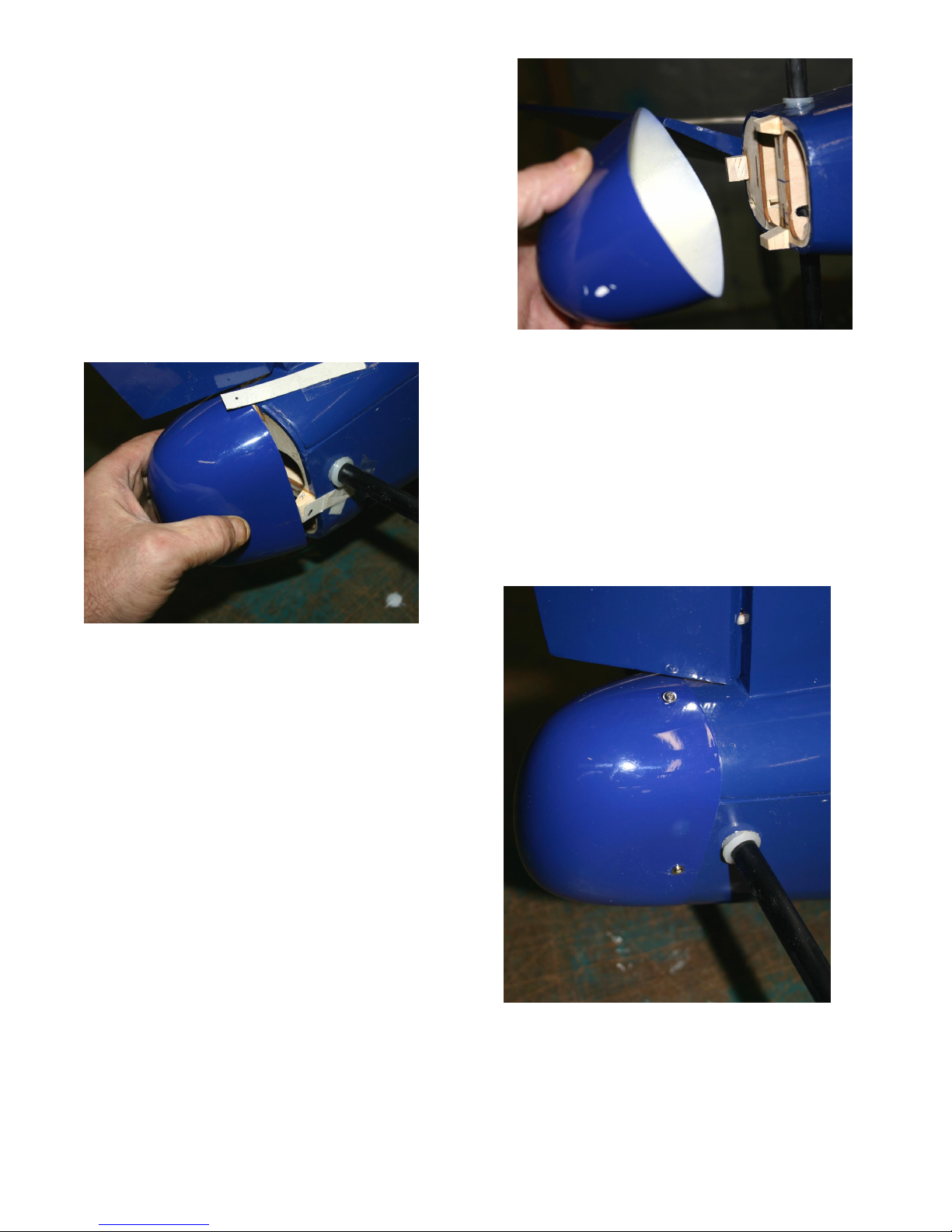
Gluethe3WoodBlocksasshownwithEpoxyGlue.
Cut3piecesofstiffCardStock1inchx4inchesandtape
themontheFuselagesothattheendsoverlapthecenterof
eachWoodenBlock.Markthese locationsontheCardStock.
GentlyslidetheEndConeintoplaceunderthetabsandtapein
place.
Drillpilotholesthroughthecentermarkswith1/16inch
drillbit.Removethe CardStock anduseWoodScrewsto
attachtheEndConethroughtheholesyoudrilled.
Page12

RudderControls
InstallRudderServointhecutoutontheServotray.
Werecommendaminimum3inchwideServoArm.
TheRudderhas2TrumpetBasesthatscrewtogetherthrough
theRudder.
PositiontheTrumpetBaseattheedgeoftheRudderbeveled
edgeand1inchfromthebottomoftheRudderandmarkwhere
todrilla5/32inchholethroughtheRudder.Installthe2
TrumpetBaseswiththeTrumpetScrew.Donotovertighten.
TIP: StrengthentheholesbyapplyingafewdropsofthinCA
glueinbothholestoreducetheamountofBalsacompression.
Page13

CutthePullPullCableinto2equallengthsandthreadtheCablethroughthehoesintherearoftheFuselage.
ThreadoneCrimpFittingovertheendofoneCable,thenthreadtheCablethroughtheouterholeintheyour
LargeRudderServoArm.FoldbacktheCable1inchandslidetheCrimpFittingovertheCableend.When
satisfiedwiththefit,crimpthefitting.RepeatfortheotherendoftheServoArmwiththeotherCable.
TIP:Usea3/4inchpieceof1/8inchshrinktubingtocoverthe
sharpendoftheCablestickingoutofthecrimpedJointatbothends
oftheCable.YouwillhavetoslidethisonCableinadvance.
InstallaclevisontotheTrumpetbaseoneachsideofthe
Rudderthesameway.
Page14

Canopy
Collecttheseparts:
ÿ Canopy
ÿ Fuselage
ÿ 440SocketHeadBolts(2)
Testfittoseethateverythingisalignedandseatedproperly.Youmayhavetosandthefronttabsslightly.
Thecanopyholddowntabstotherearofthecanopyhavebeenpredrilledwithblindnutsinstalled.
Withthecanopyinplace,pokeaholeinthecoveringatthelocationofeachblindnut.Usesupplied440socketheadbolts
tosecurecanopyinplace.
Page15

MainGear&Wheels
Collecttheseparts:
ÿ 2PrebentLandingGearWireStruts
ÿ 2–FiberglassLandingGearFairings
ÿ 4–PlywoodFairing Inserts
ÿ 4–MetalMountingStraps
ÿ 8–SmallWoodScrews
ÿ 2–MainWingHalves
ÿ 2–MainWheels
ÿ 4–WheelCollars
YoucanupgradetheappearanceofthewirelandinggearwithRobarts#674ForkedRoboStruts.
UseanXactoKnifetocutoutthecoveringovertheslotin
eachWingfortheLandingGearStruts.
TrialfiteachLandingGeartoassureatightfit.
SetintheLandingGearStrutsandposition2oftheMetal
Strapsandmarkthelocationforthescrewholes.
Drillpilotholeswitha1/16inchdrillbit.
Page16

UsethesuppliedWoodScrewstoscrewthestrapsinplace
onbothWinghalves.
SlidethelargerFairingInsertoverthewireLanding
Gearwiththenarrowendtowardsthetrailingedgeof
theWingandtracearoundit.
UsingasharpXActoKnifecutoutthecovering
approximately1/16inchinsidethetracedline.
GluethelargerFairinginsertintoplacewithCAGlue.
UseaDremilTooltoelongatetheholeinthesmallerFairing
InsertsotheFairingswon’tgetrippedoffonarough
landing.
Page17

SlidetheFairingintoplaceandgluetothebottomlarger
InsertandthetopsmallerInsert.
DrillouttheWheelAxleHolewith¼inchdrillbittofit
fittheLandingGearWire.
SlideaWheelCollarontoeachLandingGearStrut.Slidethe
WheelonandthenanotherCollar.WiththeWheelcentered
inthemiddleoftheStruttightentheWheelCollarsjusttight
enoughsotheWheelturnsfreely.
Page18
Table of contents
Other Piper Toy manuals


Popular Toy manuals by other brands


Mega Construx
Mega Construx POKEMON WONDER BUILDERS PANCHAM GFV74 manual

Mattel
Mattel Barbie K8929-0520 instructions

Eduard
Eduard MiG-21PF manual

VQ Models
VQ Models MESSERSCHMITT BF-109 instruction manual

MTHTrains
MTHTrains E-33 operating instructions

Hasbro
Hasbro G.I. Joe Ripattack Tiger Snake with... instructions


