PIREZ BBS01 User manual

Installation Manual
Mid-Drive Motor - Conversion Kit
BAFANG
BBS01/BBS02

© COPYRIGHT: PIREZ ELECTRIC BIKES, 2020.
This document remains the property of Pirez Electric Bikes.
No part of the content contained in this document may be copied, reproduced,
transmitted, distributed, downloaded or transferred in any form or by any means without
prior written consent, and with express attribution to the copyright owner, Pirez Electric
Bikes.
The only exception is that one temporary copy may be downloaded into a single
computer's memory and one unaltered permanent copy may be used by the viewer for
personal and non-commercial use only.
No part of the downloaded copy may be subsequently reproduced, disseminated or
transferred.
Note: Copyright infringement may be a violation of state or federal law subject to
penalties.

Table of Contents
1. INTRODUCTION .......................................................................................................................................1
2. SYSTEM OVERVIEW .................................................................................................................................2
ADVANTAGES OF MID-DRIVE MOTOR SYSTEMS ............................................................................................... 2
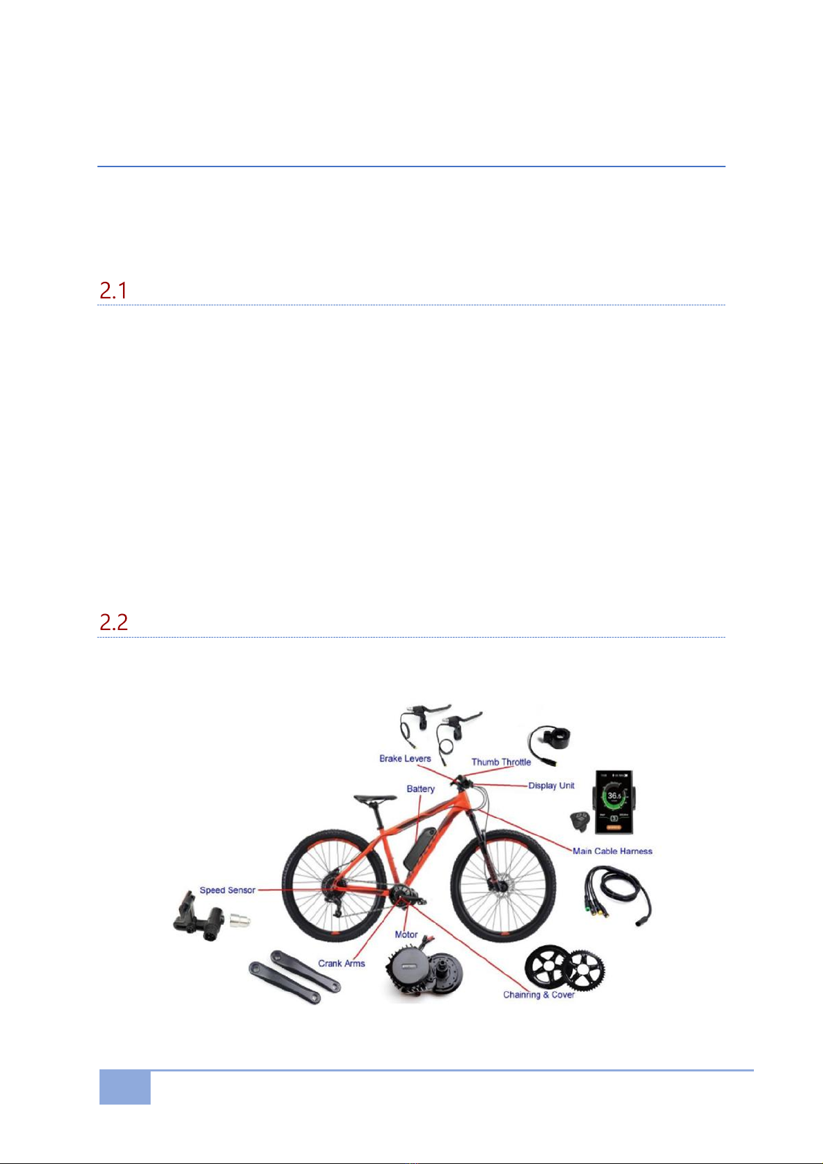
STANDARD ARRANGEMENT OF A MID-DRIVE SYSTEM ........................................................................................ 2
MOTOR CONSTRUCTION.............................................................................................................................. 3
SPECIFICATIONS ......................................................................................................................................... 3
PRECAUTIONS............................................................................................................................................ 3
3. PREPARATION .........................................................................................................................................4
CONTENTS ................................................................................................................................................ 4
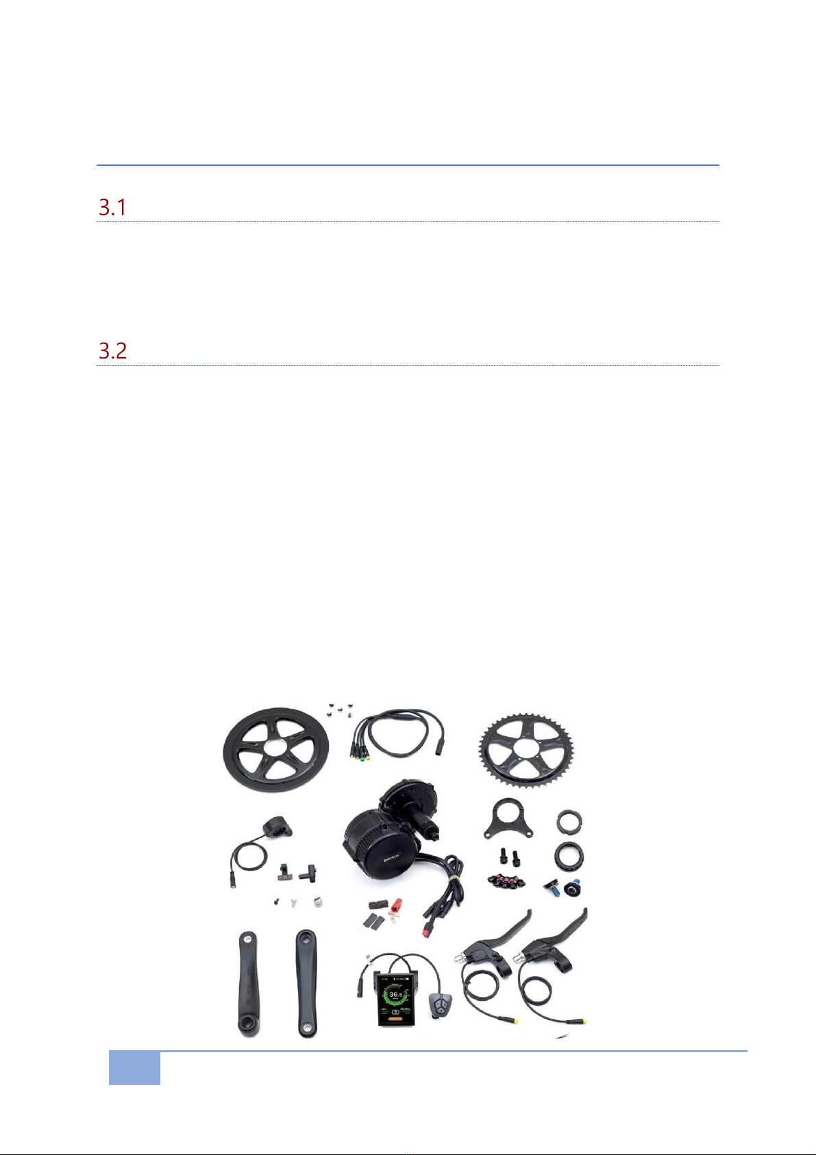
STANDARD CONVERSION KIT -COMPONENTS LIST ............................................................................................ 4
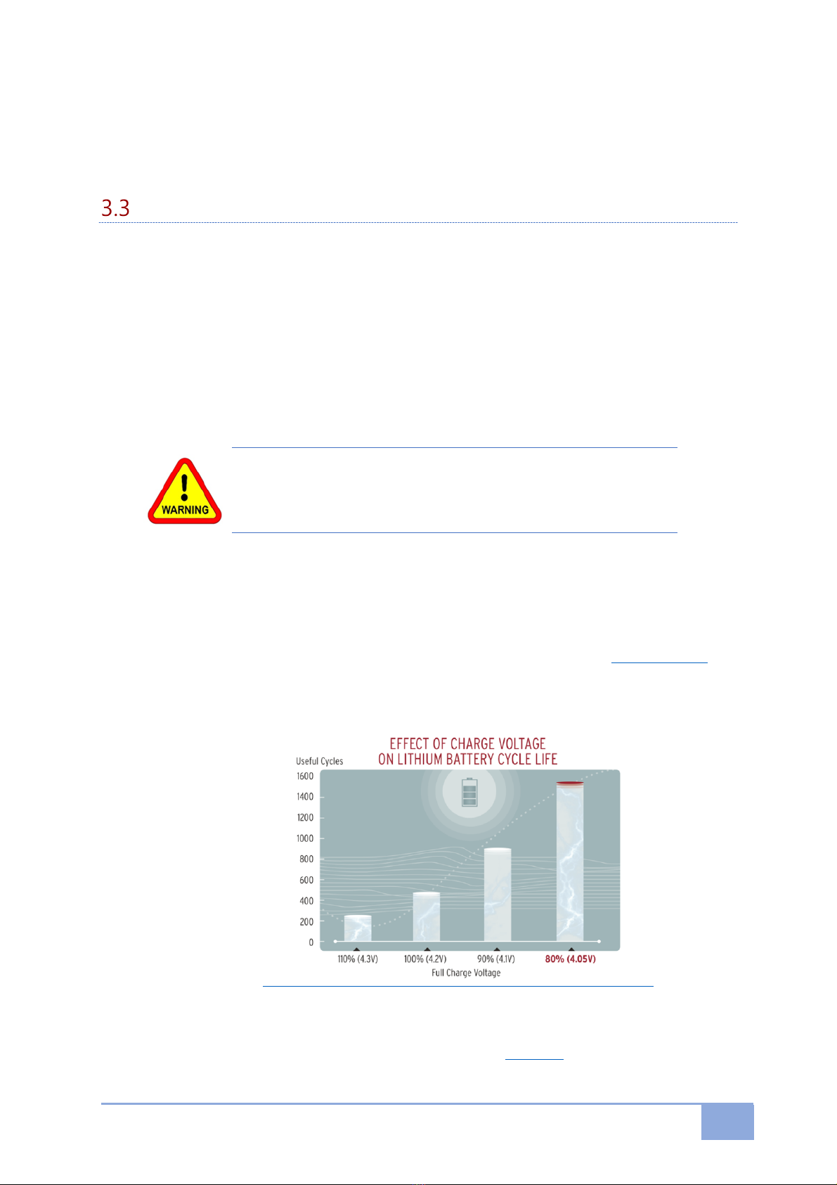
BATTERY PREPARATION ............................................................................................................................... 5
4. INSTALLATION PROCEDURE .....................................................................................................................6
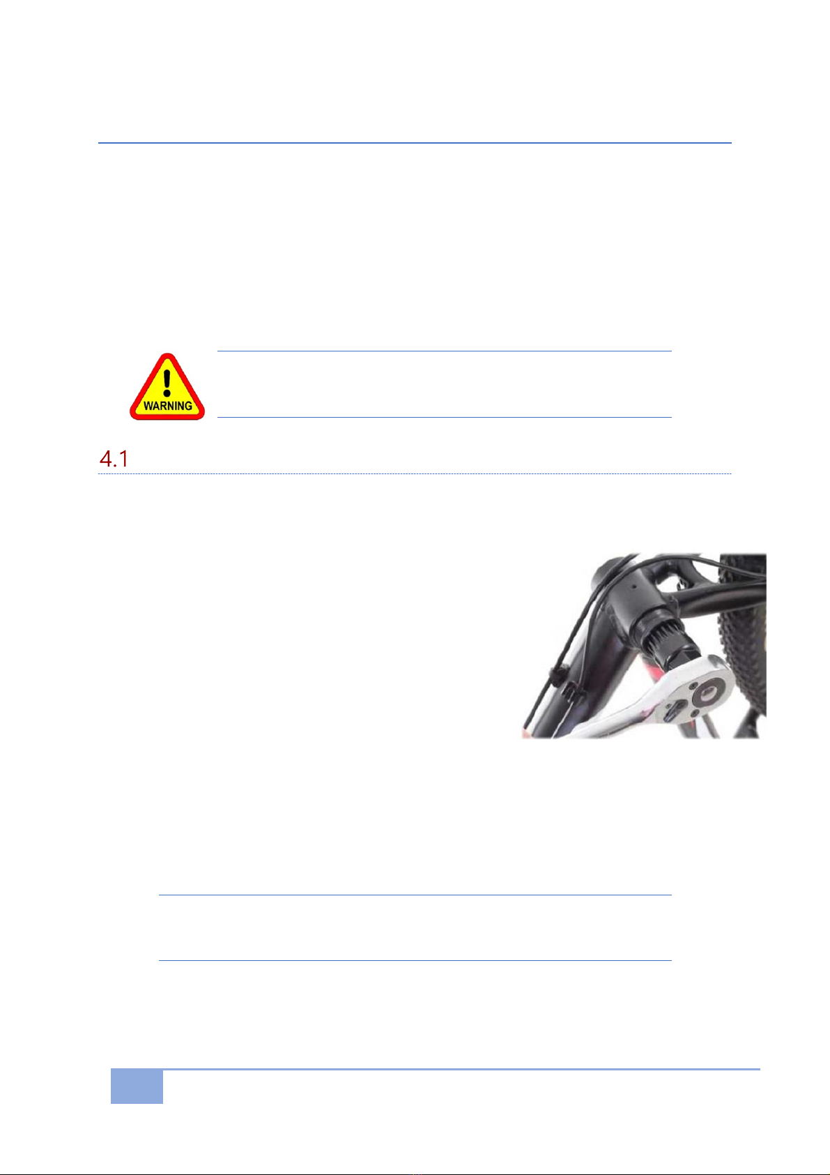
BOTTOM BRACKET REMOVAL ........................................................................................................................ 6
INSTALL THE MID-DRIVE MOTOR .................................................................................................................. 7
CHAIN RING SIZE ........................................................................................................................................ 9
CHECK THE CHAIN LINE .............................................................................................................................. 10
4.4.1 Narrow-wide tooth pattern ............................................................................................................ 10
4.4.2 Chainring upgrades......................................................................................................................... 11
4.4.3 Lekkie Benefits ................................................................................................................................ 11
4.4.4 Chainring Adapters ......................................................................................................................... 12
INSTALL THE BATTERY ............................................................................................................................... 12
INSTALL THE DISPLAY UNIT......................................................................................................................... 13
INSTALL THE BRAKE CONTROLS ................................................................................................................... 13
4.7.1 E-Brakes ......................................................................................................................................... 14
4.7.2 Brake Sensors.................................................................................................................................. 14
INSTALL THE THROTTLE.............................................................................................................................. 15
INSTALL THE SPEED SENSOR ....................................................................................................................... 16
INSTALL THE CABLING ................................................................................................................................ 16
CABLE IDENTIFICATION CHART .................................................................................................................... 17
FINALISE &NEATEN.................................................................................................................................. 18
5. SYSTEM VERIFICATION .......................................................................................................................... 18
6. OPTIONAL EXTRAS................................................................................................................................. 19
BOTTOM BRACKET -SPACERS &WASHERS ................................................................................................... 19
STABILISER BARS ...................................................................................................................................... 19
6.2.1 Non-full suspension......................................................................................................................... 19
6.2.2 Full suspension ................................................................................................................................ 19
GEAR SENSORS ........................................................................................................................................ 20
KILL SWITCH............................................................................................................................................ 20
7. GENERAL CARE & MAINTENANCE .......................................................................................................... 21
INSTALLATION AND MAINTENANCE SERVICING ............................................................................................... 21
TROUBLESHOOTING ERROR CODES .............................................................................................................. 22
8. WARRANTY ........................................................................................................................................... 23

1
1. Introduction
Congratulations on purchasing your new electric bike product.
We’re certain you'll love it, and with some care and maintenance, it will last you for a long
time.
Please read through this manual carefully before attempting to install your mid-drive
system.
Every bike is different so its difficult to provide an exact step by step procedure for your
precise configuration, however this manual is a guide which describes the basic
installation steps.
If you encounter any installation difficulties, please refer to the resources provided on our
website.
A general search on the internet may also find tutorial videos or instructions specific to
your problem, however we don’t necessarily endorse any of these methods and care
should be taken that following any of these will not cause any safety issue or void your
warranty.
If you still require assistance, feel free to contact us and we will assist where possible.

2
2. System Overview
In terms of an electric bike, mid-drive means that the ‘drive’ unit or motor is installed in
the middle of the bike positioned directly in between the pedals at the bike's bottom
bracket as opposed to a hub-drive which is positioned on the front or rear wheel, with
the motor placed in the wheel hub.
Advantages of Mid-Drive Motor Systems
Major benefits:
Can be easily installed on a standard bike frame.
Positioned at the centre of gravity provides better control.
Has high starting torque (Max torque ≥ 80Nm), which provides good performance
on climbing.
Utilises a double clutch adding to a safer operation.
Comprised of a speed sensor and torque sensor to provide the Pedal Assist feature
which helps you whilst pedalling.
Motor controller is integrated internally, which means no external wiring.
Provides high efficiency, low consumption and longer range compared to similar
output hub motors.
Standard arrangement of a Mid-Drive System

3
Motor Construction
The motor drive unit is made from die-cast aluminium with an electrophoresis black
coating.
The working environment temperature can range between 25°C – 55°C.
The ingress protection grade is rated at IP65.
This means that the unit has:
dust protection rating of 6 (no ingress of dust)
water protection rating of 5 (protected against water jets from all directions).
This is a high, water protection rating, but is not totally waterproof.
The motor should never be submerged in water, exposed to long periods of rain heavy
enough to form puddles, or high pressure washing.
Specifications
The motor provides an identification serial number on the motor casing in the following
format:
BBS01 36V 250W 15A 25km/h 13010001
This defines:
BBS01: Motor model 15A: limited current
36V: rated voltage 25 km/h: max speed
250W: rated power 13010001: Serial Number
Precautions
Our ebike conversion kits are designed to be self-installed, however it can still be a
difficult process as all bikes can vary considerably.
After many years of perfecting these installations and fixing customer mistakes, we
always recommend using an experienced e-bike technician to do your installation.
We have seen instances where a customer has damaged two motor controllers through
poor installation resulting in repair costs exceeding $300.
Please note that if you chose to install a kit to your bike yourself or with any other
technician (not affiliated with Pirez) you do this at your own risk and any damage done to
any component or bike during installation is not covered by our warranty.
For full Terms & Conditions please visit our website www.pirez.com.au. Alternately you
may choose to send your bike to us to complete the installation.We offer full installation
of the kit and battery for $250. This installation is performed by our qualified technicians
and ensures you full warranty terms for 12 months.
Whilst we have your bike onsite, our technicians can also recommend or offer additional
servicing, repairs or upgrades of particular components such as brakes and chains.

4
3. Preparation
Contents
1. Open the package and remove the drive unit and accessories
2. Confirm that the specifications of the motor are what you purchased
3. Check that all accessories and cabling have been included in the box as per the
components list below.
Standard Conversion Kit - Components List
BBS01 250W / 350W Motor -or-
BBS02 500W / 750W Motor
Display Unit (DP-C18)
Chainring
DP-C18 Grommets
Chainring Cover
DP-C18 Bolts (3 silver)
Lock Ring Nut (M33)
Main Cable Harness
Lock Ring Cover (M33)
Thumb throttle
ST 3.9 Screws (5 silver)
Speed Sensor
Bolts M5 x 10mm (5 pink)
Speed Sensor Holder with screw
Triangular Fixing Plate
Speed Sensor Magnet with screw
Bolts M6 x 12mm (2 black)
Brake Levers (2 units)
Crank Arms (1 pair)
Anderson Connectors (Spare)
Crank Arms bolts (2 blue)
Any items purchased separately or upgraded will not appear here.

5
Other required items not included in a conversion kit are freely available at retail stores or
can be purchased through our website.
This includes items such as install tools, spacers, washers, cable ties, spiral wrap, etc
Battery Preparation
Prior to installation the first time, ensure your battery is fully charged. This ensures that
the voltage and state of charge among all the internal cells is equalised or ‘balanced’.
1. Plug the charger into a general power outlet.
2. Check that one of the charger indicator lights turns green.
3. Carefully connect the charger to the battery.
4. Ensure the plug is fully inserted, but do not force it if there is an obstruction.
5. The charger indicator lights should turn red whilst charging
6. Once the battery is fully charged the charger indicator light will change to green.
There is no way to over-charge the battery.
Warning: Never leave a battery unattended whilst charging or left to
charge overnight. Extended charging could result in overheating and
cause a fire. This also reduces the longevity of your battery.
7. When it is fully charged, the charger will stop charging the battery automatically.
Charging time can vary up to several hours if fully discharged.
8. The battery should be charged to 80% at least once every 3-months as a minimum
to maintain healthy cells.
For a premium battery charging regime, Pirez can provide a superior ‘Smart Charger’
which has some unbelievable benefits including universal compatibility, fast charging,
voltage control, watertight, bike mountable and programmable to ensure battery
longevity.
For frequent or long distance riders, we also highly recommend consideration of a spare
or additional battery.
Pirez offer the largest range of 24V, 36V, 48V & 52V batteries in a range of different
models.

6
4. Installation Procedure
The following steps are a guide to install a BBS Mid-Drive motor to most standard bikes.
Some customizations may be necessary due differences in bike models, installed
accessories or even personal preference, but there are numerous resources available both
online and through our website to assist you.
But the most important point is that safety is paramount.
Take care when installing all components, particularly once the battery is connected as
the motor could engage and rotate the drivetrain which can be dangerous if its
unexpected.
Warning: The throttle can engage even if speed level is set to zero. Always
ensure the display is powered off.
Bottom bracket removal
1. Flip the bike upside down or secure on a raised work-stand to remove the original
crankset and crank arms, front derailleur and bottom bracket from the bottom
bracket shell of the bike frame.
2. Remove the crank arms using Allen keys or a
crank arm removal tool depending on what
sort of crank arms your bike has.
3. You can then use a bottom bracket remover
and ratchet handle to remove the bottom
bracket cups, as shown here.
4. Remove any front derailleur or front gear
cables. The derailleur can usually be removed
by loosening one bolt with an Allen key then
opening a clamp.
5. You will then find that the chain is looped
through the derailleur.
6. The front derailleur is not used on an e-bike so if you don’t need it you can simply
cut it off and discard, otherwise you will need to remove the chain via a quick link
or with the aid of a chain breaker tool.
7. Remove all the associated cables, then reinstate the chain if you had removed it.
All tools highlighted in bold can be purchased in kits or individually through
the Pirez website: pirez.com.au

7
Install the Mid-Drive Motor
The mid-drive motor should be installed according to the following configuration. Follow
the steps underneath.
1. Affix the chainring to the motor with the
concave surface facing in, using the five (5)
black bolts [M5*10]. Do NOT use Loctite with
these bolts.
2. Attach the chainring cover (optional) to the chainring with the five (5) silver screws
[ST3.9].
3. Carefully feed the motor drive motor axle through the bottom bracket. If you
encounter resistance your bottom bracket shell may need to have burrs or weld
overflow smoothed with a rounded file.
4. Ensure the thread of the axle extends beyond the bottom bracket more than
10mm.

8
5. With the teeth on the triangular fixing plate facing inwards, fix the plate to the
drive unit with two (2) black bolts [M6 x 10mm]. You may use Loctite on these two
(2) bolts if you wish.
6. Ensure the triangular fixing plate is aligned straight, parallel to the same plane as
the chain line or crank arms (that is perpendicular to the mid-drive axle). Use
washers with the bolts or bottom bracket spacers to keep the fixing plate perfectly
aligned.
7. These spacers and washers are available through our website.
8. The motor should be pressed up against the down tube of your bike frame before
tightening the bolts on the motor. Make sure any cables that run along the down
tube of your frame are clear from being clamped down by the motor as this could
cause these brake or gear cables to fail.
9. Rotate and hold the drive unit up against the frame and tighten the [M6 x 10mm]
bolts and then tighten the [M33] lock ring nut with a force of 30-40Nm. We
recommend that you use the correct tools specifically designed for this purpose.

9
10. These specialized installation tools can be purchased at Pirez via our website. An
example of these tools is shown here.
11. Once the lock ring nut has been tightened fit the lock ring cover over the [M33]
lock ring nut.
12. The new set of cranks arms can now be installed onto the motor axle. Check the
markings on the back of the cranks arms to distinguish between left and right. It is
particularly important you do not confuse the left and right cranks.
13. Fix the left hand (LH) crank arm to the bike with the [M8] inner hex bolt using an
8mm Allen key. Use Loctite if you wish as this bolt is prone to loosening.
14. Fix the right (RH) crank on the bike with the [M8] inner hex bolt using an 8mm
Allen key. Again, use Loctite if you wish as this bolt is prone to loosening.
15. A pair of pedals can now be installed on the crank arms. Ensure the pedal spindles
are lubricated prior to installation to prevent rust oxidation.
(Pedals not included in kit).
16. This completes the motor installation so the bike can now be returned upright to
finish the bike conversion.
Chain ring size
In the majority of cases, the standard chainring provided with your kit should be
sufficient in regard to its size, however if there is a significant difference in comparison to
your existing chain ring you may need to upgrade to a different size or alternatively a
different sized chain.
Different sized chainrings will have the following effects:
Smaller Chainring Larger Chainring
Lower Resistance Higher Resistance
More Torque More Cadence

10
Check the chain line
The chain line of a bicycle is determined by precise measurements between the centre of
the downtube relative to the chainring and then to a direct line to the centre of the rear
cassette.
This is because the chain has to move up and down the cassette as you change gears.
(Down the cassette for lower gears and up the cassette for higher gears).
When a mid-drive motor is installed this chain line may be too far outward from the
downtube and require adjustment to restore the proper chain line.
If the chain line is too far out of alignment, the chain is likely to fall off the chainring.
On many bike conversions the standard chainring will work fine. But depending on your
bike frame and accessories some chain line adjustment may be recommended or even
necessary.
Our conversion kits include a standard 46 tooth chaining.
This standard Bafang chainring, although extraordinarily strong, only has an offset of
about 2mm to bring back the chain line into alignment. This may be insufficient to
provide an acceptable chain line.
Pirez can provide other options to restore your chain line to perfect alignment.
4.4.1 Narrow-wide tooth pattern
We recommend that you use narrow-wide
chainrings because it provides better grip with
your chain which minimizes the chance of your
chain falling off.
These chainrings have a continuous, narrow tooth
followed by a wide tooth pattern.

11
This is a benefit of Lekkie chainrings which have the narrow-wide tooth pattern.
4.4.2 Chainring upgrades
Our recommendedation to improve your chainline is to upgrade to a Lekkie Bling Ring.
These chainrings range from size 28T to 52T.
These Lekkie chainrings have an
offset which moves the chain line
back into its ‘perfect’ position
eliminating chain drop.
Also, if the chain line is in its
optimum position, the drive train
will last longer and run
smoother.
A misaligned chain line may work, but will prematurely wear out the cassette, chain and
the chainring.
Remember, e-bikes are powered and the impact of motor power on your drivetrain is
much greater than human power from pedalling alone.
4.4.3 Lekkie Benefits
Besides the superior functionality,
the Lekkie chainring is made of
high-grade, light weight Aluminium
alloy and is an attractive upgrade
from the standard stamped steel
Bafang chainring.
The standard Bafang chainring and cover, although strong, may detract from the desired
look of your bike, particularly on more high-end bikes.
The lighter weight of a Lekkie Bling Ring is a benefit when riding the bike without pedal
assist due to the overall lower weight of the bike.

12
4.4.4 Chainring Adapters
Chainring adapters allow you to change to any
industry standard chainring allowing you to go
down as small as 34T to enable insane hill
climbing torque.
If you choose to use your own chainring, we
offer a range of chainring adapters to enable
these installations.
These chainring adapters can be installed with
your chainring for both the BBS01 and BBS02
motors.
BA104: For chainrings from 32T to 48T with a 104mm BCD
BA110: For chainrings from 33T to 54T with a 110mm BCD
BA130: For chainrings from 38T to 55T with a 130mm BCD
Note: BCD = bolt circle diameter
Warning: Never install or refit a fallen chain whilst the battery is on.
For safety reasons, we recommend disconnecting the battery to prevent the
motor from engaging accidently.
Install the Battery
Prior to installation, we recommend fully charging your battery before its first use.
Ensure your battery is compatible with your motor. Specifically, ensure that the voltage is
the same. Test with a voltmeter if you are unsure.
Note: An incompatible battery could damage the motor controller and would void
the warranty. In this instance, CE certifications & MSDS sheets for the applicable
battery would be required to accompany a warranty claim.

13
1. Ensure your battery is installed securely in its position
2. Pirez supply customised securing straps
with some battery types as shown here.
These Pirez Velcro Straps can be
purchased via our website.
3. Specific battery installation instructions
are not provided here due to the large
range of battery options.
4. Refer to our website or your own battery
supplier for further assistance.
Install the Display Unit
The display unit included with the conversion kit is
the BAFANG DP-C18.
This device will support you in configuring your
wheel size and adjusting the speed limiter and power
level.
1. Install the display and button control on the
handlebar using the two rubber grommets
and three screws supplied.
2. Adjust its location to your preference so that it
will be easy to glance at whilst riding.
3. Attached to the Display Unit is the Pedal Assist
Controller (PAC), which includes the ON/OFF and
control buttons.
4. The PAC should be slid onto the handlebars on the side preferred by the rider. This
will be affected by where you placed the
Display Unit, the type of throttle you
have and your brake levers.
5. Tighten the screw in the holder once the
switch is in a comfortable position.
6. Plug it into the motor controller with
the power off.
7. Keep the plug cap to reuse anytime the
cable is disconnected. This will help
protect the green plug of your display.
Install the Brake Controls
Each conversion kit includes a new set of electric brake levers.
You can choose to either install the new e-brake levers provided with your kit or purchase
a set of brake sensors to use with your existing brake system.

14
4.7.1 E-Brakes
The standard conversion kit provides a pair of e-brake
levers as shown here.
These can be installed in place of any existing brakes,
then simply connected to the main cable harness
using the yellow plugs.
4.7.2 Brake Sensors
Pirez offer two styles of brake sensors that can be used with your existing brake system.
Our Universal and Inline sensors are both described below.
Note: Using V-Brakes with an electric bike is not recommended.
4.7.2.1 Universal Brake Sensors
These sensors can be used for any type of brake
system (including both hydraulic and disc brakes)
which allows you to convert your already existing
brakes into e-brakes.
This sensor is a simple piece of hardware which is
basically a reed switch. When the magnet is close to
the rectangle sensor (reed switch) the circuit is open,
and the controller lets power pass through to the motor.
When you pull the magnet further away from the sensor, the switch closes the circuit that
sends voltage to the controller which then instantly cuts the power to the motor.
1. To install, simply plug the brake sensor (yellow plug) into the main cable wiring
harness.
2. Attach the rectangle reed switch and the
magnet on the brake lever, as shown here.
3. There are numerous possible configurations
depending on the style of the brake lever
however generally speaking, the sensor should
be attached to the static brake lever housing
and the magnet should be attached to the
movable break lever handle close to the pivot
point.
4. We recommend that you use the double sided tape provided, to affix the sensor
and magnet to the brake lever.
5. Once you have tested the functionality of the sensor and it is working as desired,
you can more permanently fix them using either cable ties, super glue, epoxy glue,
hot glue, etc.

15
4.7.2.2 Inline Brake Sensors
Inline brake sensors work by detecting the movement
of the brake cable which is threaded through the
sensor. They are compatible with all brake types that
have a protruding brake cable.
Note: The inline sensors are NOT compatible with
Hydraulic brakes.
1. To install, thread the brake cable through the hole in the centre of the sensor and
install at the base of the brake lever housing.
2. The arrow on the sensor should point towards the brake lever.
3. When the brake cable is pulled the movement is detected and will cut off the
motor power instantly.
Note: The sensor can be installed anywhere along an exposed section of the brake cable
wherever there is a join between the wire cable and the protective plastic sheath.
Install the Throttle
The standard conversion kit includes a
universal thumb throttle as shown here.
The most common setup for the throttle is to place it on
the left hand side of the handlebar, however this
depends on rider preference, and this universal device
can be used on either side.
To install the thumb throttle, you will need to remove
any existing hand grips and other components first.
Other types of throttle are available for purchase as shown below. These include full twist,
half twist and swing throttles.
To purchase any of these throttles you must first determine whether you prefer the
throttle on the left or right.

16
Install the Speed Sensor
The speed sensor measures the wheel revolutions and
transmits to the display
unit. The speed and mileage will be shown on
the display unit.
The speed sensor is comprised of the sensor, plastic
holder with screw, spoke magnet with screw.
1. Assemble the speed sensor with the plastic
holder and tighten the screw according to the image shown here.
2. Using the double sided tape, affix the speed sensor holder to the inside of the
chainstays.
3. Affix the sensor magnet to one of the spokes on the rear wheel so that the magnet
aligns with the sensor when the wheel turns.
4. The magnet must face the sensor and should be no more than 5mm apart.
5. Once you are satisfied that the sensor is aligned with the magnet, cable tie the
holder to the chainstays to secure it in place.
6. Connect the speed sensor cable to the sensor and to the main cable harness.
7. Test the sensor with the Display Unit turned on.
If the sensor and magnet are not aligned or close enough to be detected the
Display will indicate an Error Code 21: Speed Sensor Fault.
In this instance, adjust the sensor or magnet accordingly.
Install the cabling
All the cables must now be connected so that everything has power and will function
correctly.
Most of the cables are colour coded to make it easier to identify and match the
corresponding plug for each cable.
The following diagram is provided to help identify each cable and plug.
If any of these cables are too short to suit your requirements, Pirez have a range of
compatible extension cables.

17
Cable Identification Chart
Connect all cables according to this diagram.
Main Cable - Wiring Harness
Display Unit (green - male)
Left Brake Levers or Sensor (yellow – female)
Right Brake Lever or Sensor (yellow – female)
Throttle (yellow – male)
Main cable to motor (black - female)
Motor controller cables
6-Volt Light
Motor to main cable (black - male)
Speed Sensor (black/screw clamp)
Gear Sensor (yellow – female)
Battery (red/black)
Take care to not damage the pins when connecting plugs
This manual suits for next models
1
Table of contents
Popular Engine manuals by other brands

GEIGER
GEIGER INline System GSI56 r Series Original assembly and operating instructions

Navistar
Navistar MaxxForce 3.2H Euro V Operation and maintenance manual

Black Bruin
Black Bruin BB series GENERAL INSTRUCTIONS FOR SAFETY AND USE

Azbil
Azbil ECM3000 Series user manual

FPT
FPT CURSOR 87TE4 Use and maintenance

Lifan
Lifan M13E owner's manual

Horizon Hobby
Horizon Hobby Evolution 152GX user guide

EuroLite
EuroLite MD-3010 user manual

Hyundai Seasall
Hyundai Seasall H380 series Installation & operating instructions

Technify Motors
Technify Motors TAE 125-02-114 Manual supplement

Alpha Motors
Alpha Motors WSER50 Series quick start guide

Briggs & Stratton
Briggs & Stratton 400400 Series owner's manual