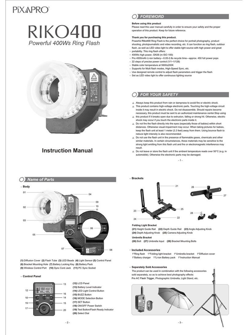
Pixapro ST-IV+ L User manual

TTLWireless FlashTrigger
Instruction Manual
www.essentialphoto.co.uk
Made in China 705-XP2L00-00
PIXAPRO LTD.
UNIT 5 Sterling Park, Pedmore Road,
Brierley Hill, West Midlands,
DY5 1TB el: +44 (0)121 552 113
E-mail: info@essentialphoto.co.uk

Contents Foreword
Thank you for purchasing this ST-IV+ L wireless ash trigger.
This wireless ash trigger applies for using Leica camera to control PiXAPRO ash,
controls the ashes with built-in PiXAPRO wireles ONE system e.g. camera ashes,
outdoor ashes, and studio ashes. Featuring multi-channel triggering, stable signal
transmission and quick response, this ash trigger benets photographers for
exible light distribution and various shooting demands, which is suitable for
hotshoe-mounted Leica cameras and cameras with PC synchronous socket. The
ash trigger suppos TTL ash and high-speed ash synchronization, and the
maximum ash synchronization speed is up to 1 / 8000s.
Warning
Do not disassemble. Should repairs become necessa, this product must be sent
to an authorized maintenance center.
Always keep this product d. Do not use in rain or in damp conditions.
Keep out of reach of children.
Do not use the ash unit in the presence of ammable gas. In ceain
circumstance, please pay attention to the relevant warnings.
Do not leave or store the product if the ambient temperature reads over 50℃.
Turn o the ash trigger immediately in the event of malfunction.
Obsee precautions when handling batteries
- Use only batteries listed in this manual. Do not use old and new batteries or
batteries of dierent types at the same time.
- Read and follow all warnings and instructions provided by the manufacturer.
- Batteries cannot be sho-circuited or disassembled.
- Do not put batteries into a re or apply direct heat to them.
- Do not attempt to inse batteries upside down or backwards.
- Batteries are prone to leakage when fully discharged. To avoid damage to the
product, be sure to remove batteries when the product is not used for a long time
or when batteries run out of charge.
- Should liquid from the batteries come into contact with skin or clothing, rinse
immediately with fresh water.
* 1/8000s is achievable when the camera has a max camera shutter speed of 1/8000s.
Foreword
Warning
Names of Parts
As a Wireless Camera Flash Trigger
As a Wireless Outdoor Flash Trigger
As a Wireless Studio Flash Trigger
Power Switch
Power Saving Mode Settings
Power Switch of AF Assist Beam
Channel Settings
Wireless ID Settings
Scanning Spare Channel Settings
Mode Settings
Magnification Function
Output Value Settings (Power Settings)
Flash Exposure Compensation Settings
Multi Flash Settings (Output Value,
Times and Frequency)
Modeling Lamp Settings
ZOOM Value Settings
Buzz Settings
PC Socket Settings
SHOOT Function Settings
Bluetooth Settings
APP Downloading
MENU: Setting Custom
Functions
Compatible Flash Models
Compatible Camera Models
Technical Data
Restore Factory Settings
Firmware Upgrade
Attentions
Caring for Flash Trigger
24
24
25
25
26
27
27
27
28
28
29
29
30
30
30
31
31
32
32
33
33
34
34
35
35
35
36
36
37
41
42
42
43
44
44
45
Body
LCD Panel
Battery Installation
Battery Level Indication
23 24

Body
LCD Panel
1. Channel (32)
2. ID(99)
3. Camera Connection
4. Group Mode
5. Beeper
6. Modeling Lamp Master Control
7. Batte Level Indication
8. Group’s Modeling Lamp
9. Group
10. Icons of Function Button
11. Output Power Level
12.HSS Delay
Multi Groups Display Single Group Display
-- Green:
Trigger (Flash) + Focus (Camera)
-- Red:
Trigger (Flash)+ Shutter (Camera)
Group Button 1
Group Button 2
Group Button 3
Group Button 4
Group Button 5
Function Button 2 Function Button 3
LCD Panel
Function Button 4
Function Button 1
<MODE.LOCK> Button
TEST/Shutter Button
Select Dial
MENU Button
Magnification Button
SET Button
STATUS Status Indicator Lamp
B
C
D
E--
M
ALL ZOOM
10
--
--
--
AM
GR SYNC ZOOM
1/16
Zoom 24mm
CH30 ID CH30 ID
A
Multi Groups’ ZOOM Display
Zoom AUTO
B
C
D
E
Zoom 24
Zoom 24
Zoom 24
Zoom 24
CH30 ID
A
Names of Parts
Menu
V 0.81/2
DELAY STEP
TCM
SHOOT
Hot Shoe Camera
Connection
AF Assist Beam Switch
--ON (AF Assist Beam outputs)
--OFF(AF Assist Beam
do not output)
Power Switch
--ON (Power On)
--OFF (Power Off)
2.5mm Sync
Cord Jack
Type-C USB Port
Battery Compartment
Assist Lamp
B
C
D
E--
M
ALL ZOOM
10
--
--
--
CH30 ID
ACH30
A
B
C
D
E--
M10 10%
10%
10%
10%
10%
--
--
--
ALL ZOOM
1
9
4
7
8
6
11
10
5
3
ID
2
12
25 26

As a Wireless Outdoor Flash Trigger
Turn off the camera and mount the transmitter
on camera hotshoe. Then, power on the flash
trigger and the camera.
Short press the < MENU > button to enter the C.
Fn Menu to set channel and group. Short press
<MODE.LOCK> button to set flash trigger mode,
turn the select dial to set flash trigger level. (refers
to the contents of “Setting the Flash Trigger”)
Power on the outdoor flash and press the wireless setting button and the wireless
icon will be displayed on the LCD panel. Long press the <GR/CH> button to set the
same channel to the flash trigger, and short press the < GR/CH> button to set the
same group to the flash trigger (Note: please refer to the relevant instruction manual
when setting the outdoor flashes of other models).
Press the camera shutter to trigger and the status lamp of the flash trigger turns red
synchronously.
1.
3.
4.
2.
Take CITI600Pro as an example:
Battery Installation
Slide the battery compartment lid of the flash
trigger and insert two AA batteries (optional)
separately.
Battery Level Indication
Check the battery level indication on the LCD panel
to see the remaining battery level during the usage.
As a Wireless Camera Flash Trigger
Turn off the camera and mount the transmitter
on camera hotshoe. Then, power on the flash
trigger and the camera.
Short press the < MENU > Button to enter the
C.Fn. menu, turn the Select Dial to < wireless
function > and press the < SET > Button to set
groups, mode and other parameters.
The battery indication only refers to AA alkaline batteries. As the voltage of Ni-MH battery tends to
be low, please do not refer to this chart.
Battery Level Indication
3 grids
2 grids
1 grid
Blank grid
Blinking
Power Status
Full
Middle
Low
Low power , please replace it.
2.5V The battery level is going to be used out
immediately (please replace new batteries, as low
power leads to no flash or flash missing in case of
long distance).
As a Wireless Studio Flash Trigger
Turn on the camera flash, press the wireless setting button and the wireless icon
and <RX> icon will be displayed on the LCD panel. Short press the < MENU >
Button to enter the C.Fn. menu, press the <CH> button to set the same channel to
the flash trigger, and press the <Gr> button to set the same group to the flash
trigger. (Note: please refer to the relevant instruction manual when setting the
camera flashes of other models)
Press the camera shutter to trigger and the status lamp of the flash trigger turns
red synchronously.
Turn off the camera and mount the transmitter on
camera hotshoe. Then, power on the flash trigger
and the camera.
1.
3.
4.
1.
2.
Take V1 series camera flash as an example:
Take STORM III as an example:
27 28
A
M
21

Power Saving Mode Settings
Power Switch of AF Assist Beam
The system will automatically enter standby mode after 60sec/30min/60min of idle
use. And the displays on the LCD panel will disappear.
Note: Dormancy time is adjustable in MENU-STBY.
Press any button to wake up. If the flash trigger is attached to the hot shoe of CANON
EOS camera, half press the camera shutter can also wake the system up.
Note: If you don't want to set the power saving mode, press < MENU > Button to enter the C. Fn Menu
and set STBY to OFF.
Short press the < MENU > Button to enter the C. Fn
menu. Turn the Select Dial to select< > and press the
< SET > Button to the setting page, turn Select Dial to ID
and short press <SET> Button to enter ID settings. Turn
Select Dial to select OFF/1-99, and then short press
<SET> to exit form ID settings.
Push the AF Assist Beam Switch up to ON, and the AF lighting is allowed output.
When the camera cannot focus, the AF assist beam will turn on; when the camera can
focus, the AF assist beam will turn off.
Channel Setting
Short press the < MENU > Button to enter the C. Fn
menu.Turn the Select Dial to select< >and press the <
SET > Button to the setting page to select CH and press
<SET> button to enter channel settings. Turn Select Dial
to select 1-32 channels, then short press <SET> button
to exit from channel settings.
Notes: please set the transmitter and the receiver to the same
channel before usage.
Wireless ID Settings
In addition to changing the wireless transmission channel to avoid interference, we
can also change the wireless ID to avoid interference.
1.
2.
1.
2.
Note: the wireless ID and channel of lead control unit and follow
control unit must be consistent before triggering.
Power Switch
Slide the Power Switch to ON, and the device is on and status indicator lamp will not
reveal.
Note: In order to avoid power consumption, turn off the transmitter when not in use.
Short press the < MENU > button to enter the C. Fn Menu to set channel and
group. Short press <MODE.LOCK> button to set flash trigger mode, turn the
select dial to set flash trigger level. (refers to the contents of “Setting the Flash
Trigger”)
Connect the studio flash to power source and power it on. Long press the
MODE/Wireless button to make the wireless icon displayed on the panel and
enter 2.4G wireless mode.Long press the <GR/CH> button to set the same
channel to the flash trigger, and short press the < GR/CH > button to set the
same group to the flash trigger (Note: please refer to the relevant instruction
manual when setting the studio flashes of other models).
Press the camera shutter to trigger. And the status lamp of the camera flash and
the flash trigger both turn red synchronously.
Note: As the studio flash’s minimum output value is 1/32, the output value of the flash trigger should
be set to or over 1/32. As the studio flash do not have TTL and stroboscopic functions, the flash
trigger should be set to M mode in triggering.
2.
3.
4.
29 30
1/2
ID 20
21
22
SCAN
DIST
CH
1/2
99
1
SCAN
DIST
CH
ID
OFF

Switch between multi-group and one-group mode: choose a group in multi-group
mode and press the < > button to magnify it to one-group mode. Then, press the
< > button to back to multi-group.
Press the group button to choose the group, turn the select dial, and the power
output value will change from Min. to 1/1 or Min. to 10 in 0.3 or 1/3 stop
increments. Then, press <SET> Button to exit from this setting.
Press Function Button 1 (<ALL> button) to choose all groups’ power output
value, turn the select dial, and all groups’ power output value will change from
Min to 1/1 or Min. to 10 in 0.3 or 0.1 stop increments. Press Function Button 1
(<ALL> button) again to confirm the setting.
Turn the select dial and the group’s power output
value will change from Min to 1/1 in 0.3 or 0.1 stop
increments.
Note: Min. refers to the minimum value that can be set in M or Multi
mode. The minimum value can be set to 1/128 0.3, 1/256 0.3, 1/512
0.3, 1/128 0.1, 1/256 0.1, 1/512 0.1, 3.0 (0.1), 2.0(0.1) and 1.0 (0.1)
according to MENU-STEP. For most of camera flashes, the minimum
output value is 1/128 or 1/128(0.1) and cannot be set to 1/256 or
1/256(0.1). However, the value can change to 1/256 or 1/256(0.1) when
using in combination with PiXAPRO strong power flashes e.g.
CITI600Pro, etc.
Magnification Function
Output Value Settings (Power Settings)
Scanning Spare Channel Settings
Mode Setting
Scanning spare channel function is useful to avoid
interference from others’ using the same channel.
Short press the < MENU > button to enter the Menu,
turn the select dial to choose < >, short press the
SET button to enter the wireless setting, then turn the
select dial to choose SCAN option. Short press the
SET button to enter the SCAN setting interface, turn
the select dial to choose START, then short press the
SET button to scan from 5% to 100%, and 8 groups of
spare channels will displayed.
Short press the group button to choose group, then short press <MODE.LOCK>
button, the mode of the chosen group will change.
When displaying multiple groups, press the
<MODE.LOCK > button to switch the multi-group
mode to MULTI mode. Press the group selection
button to choose a group, short press
<MODE.LOCK > button can set the MULTI mode
to ON or OFF, short press it once can exit MULTI
mode.
When displaying multiple groups, press the group
selection button to choose a group, short press
<MODE.LOCK > button, and all the current group’s
mode will be changed by the order of TTL/M/--.
When displaying single group, short press
<MODE.LOCK > button, and the current group’s
mode will be changed by the order of TTL/M/OFF.
B
C
D
E--
ON
1/256
3 Times
7Hz
ON
ON
TIMES ZOOM
MULTI
--
CH30 ID
A
Hz
B
C
D
E--
M
1/256+0.3
ALL ZOOM
--
--
--
CH30 ID
A
B
C
D
E--
TTL 0.0
--
--
--
CH30 ID
A
LOCKED
B
C
D
M
M
M
M
M
1/16 +0.7
+0.3
1/128
1/128
1/128
1/128
ALL ZOOM
CH30
A
SYNC
E
1.
2.
3.
1.
1.
2.
Set the groups to five groups (A-E) and( ) is ( ON ):
Set the groups to 16 groups (0-F):
When displaying multiple groups or single group, there
is only manual mode M.
Long press the <MODE.LOCK > button for 2 seconds
until “LOCKED” is displayed on the bottom of the LCD
panel, which means the screen is locked and no
parameters can be set. Long press the <MODE.LOCK >
button again to unlock.
Multi-group displays in the M mode
One-group displays in the M mode
31 32
1/2
20 19 21 07
06 23 22 10
DIST
CH
ID
SCAN

Press the group button to choose the group, turn the
select dial, and the FEC value will change from -3 to
~3 in 0.3 stop increments. Press the <SET> button to
confirm the setting.
Press Function Button 1 (<ALL> button) to choose all
groups’ FEC value, turn the select dial, and all
groups’ FEC value will change from -3 to 3 in 0.3
stop increments. Press Function Button 1 (<ALL>
button) again to confirm the setting.
In the multi flash (TTL and M icon are not displayed).
The three lines are separately displayed as power output value (1/128~1/4 ),
Times (flash times) and Hz (flash frequency).
Turn the Select Dial to change the power output value from 1/128 to 1/4 in
integer stops
Short press the Function Button 1 (TIMES button) can change flash times. Turn
the select dial to change the setting value.
Short press the Function Button 1 (HZ button) can change flash frequency. Turn
Flash Exposure Compensation Settings
Modeling Lamp Settings
B
C
D
E--
TTL +0.7 PROP
100%
47%
50%
50%
TTL +0.7
TTL +0.7
ALL ZOOM
--
CH30
A
TTL
+0.7
Zoom AUTO
PROP
GR ZOOM
CH30
A
B
C
D
E
Zoom 200
Zoom 200
Zoom 200
Zoom 200
Zoom 200
CH30
A
Multi-group displays in the TTL mode
Turn the select dial and the group’s power output
value will change from -3 to 3 in 0.3 stop increments.
Multi Flash Settings (Output Value,
Times and Frequency)
Conditions for setting the multi flash parameters: 5
(A-E) should be selected in the menu < >GROUPS,
and multi flash should be turned on.
When displaying multiple groups, short press the
<MODE.LOCK> button to enter multi flash setting
interface.
Note: Min. refers to the minimum value that can be set in M or Multi mode. The minimum value can
be set to 1/128 0.3, 1/256 0.3, 1/512 0.3, 1/128 0.1, 1/256 0.1, 1/512 0.1, 3.0 (0.1), 2.0(0.1) and 1.0
(0.1) according to MENU-STEP.
Note: As flash times are restricted by flash output value and flash frequency, the flash times cannot
surpass the upper value that permitted by the system. The times that transported to the receiver end
are a real flash time, which is also related to the camera’s shutter setting.
When displaying multiple groups, press the Function
Button 4 button to control the ON/OFF of the modeling
lamp.
Press the group button to choose the group when
displaying multiple groups, press the Function Button 4
button to control the status of the modeling lamp: OFF
(--), Percentage value (10%-100%) or PROP (auto
mode, changes with the flash brightness)
ZOOM Value Settings
Short press the Function Button 3 and the ZOOM value will
be displayed on the LCD panel. Choose the group and turn
the select dial, and the ZOOM value will change from
AUTO/24 to 200. Choose the desired value and long press
the Function Button again to back to the main menu.
(note: The models that can use one-group to ON/OFF the modeling lamp are as follows: GSII, SKII, QSII, QDII,
DEII, DPII series, etc. The outdoor flash PIKA200 and CITI600 can use this function after upgrade. The new
arrivals with modeling lamps can also use this function.).
One-group displays in the TTL mode
When the modeling lamp is in the percentage value status, long press the Function
Button 4 to enter the modeling lamp brightness value setting interface, and turn the
select dial to select the desired modeling lamp percentage value.
When displaying a single group, it is the same as the above-mentioned multiple groups
display operation.
1.
1.
1.
2.
3.
4.
5.
6.
1.
2.
2.
B
C
D
E--
ON
1/256
3 Times
7Hz
ON
ON
TIMES ZOOM
MULTI
--
CH30 ID
A
Hz
B
C
D
E--
TTL 0.0
0.0
0.0
PROP
100%
47%
50%
50%
TTL
TTL
GR ZOOM
CH30
A
--
GR
the select dial to change the setting value.
Until any value or three values are set, short press the <MODE.LOCK> button to
exit the setting status.
33 34

IN
PC JACK
OUT
L-858
SHOOT
PC Socket Settings
Press the <MENU> button to enter C.Fn menu, turn the
select dial to <PC>, and press the <SET> button to enter
PC socket setting to choose IN or OUT. Press the
<MENU> button again to back to the main menu.
When choosing IN, it will enable ST-IV+ L to trigger flash.
When choosing OUT, it will send trigger signals to trigger
other flash.
SHOOT Function Settings
Press the < MENU > Button to enter the C.Fn menu and turn
the Select Dial to select <SHOOT>, then short press the <
SET> button and turn Select Dial to select One-shoot/
Multi-shoots/L-858,after that press <MENU> Button return
to the main menu.
Buzz Settings
Press the < MENU > Button to enter the C. Fn menu, turn the Select Dial to < >, press
the < SET > Button to enter and turn the Select Dial to select ON/OFF turned on or off.
Then press the < MENU > Button return to the main menu.
When choosing ON, the beeper is turned on.
When choosing OFF, the beeper is turned off.
Bluetooth Settings
APP Downloading
Check Bluetooth MAC code: Short press the MENU button to enter the C.Fn menu, turn
the select dial to select < >, then short press the SET button to enter the Bluetooth
setting interface, and the Bluetooth MAC code is displayed in the bottom right corner.
Bluetooth Reset: Short press the MENU button to enter the C.Fn menu, turn the select dial
to select < >, then short press the SET button to enter the Bluetooth setting interface,
turn select dial to choose “RESET”and short press the SET button to enter “RESET”, then
you can reset the Bluetooth as you wish. It will automatically return to the previous setting
interface after the reset is completed.
Scan the following QR code to download “GODOX Flash” APP. (available for both
Android and iOS systems)
Note: the APP can be used directly on the firstly installed device
(smartphone or tablet). When changing to other mobile device,
the light shall be reset before the normal usage of APP.
The Bluetooth initial password is 000000.
For more smartphone APP operations, please open
the "help" in the APP to gain detailed guidance.
One-shoot: When shooting, choose one-shoot. In the M and Multi mode, the lead unit
only sends triggering signals to the follow unit, which is suitable for one person
photography for the advantage of power saving.
Multi-shoots: When shooting, choose multi-shoots, and the lead unit will send
parameters and triggering signals to the follow unit, which is suitable for multi person
photography. However, this function consumes power quickly.
L-858: The flash parameters can be adjusted directly on Sekonic L-858 Light Meter when
collocating with it , and the transmitter only transmits SYNC signal.
35 36

Icons Functions
Multi flash
Wireless
Setting Icons Settings and Description
Icons Functions Setting Icons Settings and Description
Bluetooth
CH
ID
SCAN
DIST
GROUPS
BLUE.T
RESET
Turn on multi flash
Turn off multi flash
Turn off HSS delay
0.1ms-9.9ms:HSS delay range
The minimum output is 1/128
(change in 0.3 step)
The minimum output is 1/256
(change in 1/3 step)
The minimum output is 1/512
(change in 1/3 step)
The minimum output is 1/128
(change in 0.1 step)
The minimum output is 1/256
(change in 0.1 step)
The minimum output is 1/512
(change in 0.1 step)
The minimum output is 3.0
(change in 0.1 step)
The minimum output is 2.0
(change in 0.1 step)
The minimum output is 1.0
(change in 0.1 step)
OFF:off
1-99:optional 01-99 Choose
any figure from 01-99
OFF: off
START: Start scanning spare
channel
1-100m:1-100m triggering
0-30m:0-30m triggering
5(A-E):5 groups
16(0-F):16 groups
0FF: off
ON: on
CANCEL: cancel
RESET: Bluetooth reset
32:1-32 HSS delay
Power
output value
ON
OFF
OFF
0.1ms-9.9ms
1/128 0.3
1/256 0.3
1/512 0.3
1/128 0.1
1/256 0.1
1/512 0.1
3.0 (0.1)
2.0 (0.1)
1.0 (0.1)
MENU: Setting Custom Functions
The following table lists the available and unavailable custom functions of this flash:
DELAY
STEP
37 38

Icons Functions Setting Icons Settings and Description Icons Functions Setting Icons Settings and Description
Only send triggering signals in
the M & Multi mode when
camera is shooting
Trigger testing
Shutter testing
In port, enable ST-IV+ L to
trigger flash
Out port, send trigger signals
to trigger other flash
turn off Beeper
turn on Beeper
Enter sleep mode after 60
seconds of idle use
Enter sleep mode after 30
minutes of idle use
Enter sleep mode after 60
minutes of idle use
The contrast ration can be
set as integral number from
-3 to +3
Off in 12 seconds
Always off
Always lighting
turn off sleep mode
Send parameters and triggering
signal when camera is shooting
(suitable for multi person
photography)
The flash parameters can be adjusted
directly on Sekonic L-858 Light Meter when
collocating with it, and the transmitter only
transmits SYNC signal
turn off TCM transform function
Li-ion580III series
Transform the
TTL shooting
value into the
output value in
the M mode.The
main light mode
shall prevail in
mixed use.
CITI100Pro
PIKA200
CITI300Pro
CITI400Pro
CITI600, 600PRO
CITI1200Pro
turn off legacy hot shoe
turn on legacy hot shoe, TTL flash
is unavailable, HSS function is
also unavailable
OFF
ON
One-shoot
Full-shoot
Connect to
L-85 8 L-858
TCM
transform
function
Legacy
hot shoe
SHOOT
TCM
100j
200j
300j
360j400j
600j
120 0j
OFF
OFF
12sec
ON
PC socket
Beeper
Sleep
LCD
Backlighting
TRIGGER
SHUTTER
TEST
button
IN
OUT
OFF
ON
60 sec
30 min
60 min
-3-+3
LCD
contrast
ratio
OFF
LCD
PC
Z
Z
Z
39 40

Icons Functions Setting Icons Settings and Description
CANCEL
SAVE:1-4
CANCEL
Import:1-4
Clear data from menu
Compatible Flash Models
Transmitter
ST-IV+ L ---
Receiver Flash models
Li-ion580III series, V1 series, CITI100Pro,
PIKA200, PIKA200Pro, CITI300Pro,
CITI400Pro,
CITI600Pro, CITI1200Pro, P2400(Note
1), Quicker series flashes(Note 2)
1.Firmware upgrade is
needed to support ST-IV+
L.
2.Early version of these
flashes may not support
HSS, please pay attention
to the firmware version.
Note: The range of support functions: the functions that are both owned by
ST-IV+ L and flash.
Note
Compatible Camera Models
Technical Data
This flash trigger can be used on the following Leica camera models:
This table only lists the tested camera models, not all Leica EOS series cameras.
For the compatibility of other camera models, a self-test is recommended.
Rights to modify this table are retained.
There are shining edges in HSS flash when collocating with certain models.
There are missing flashes in quickly continuous shootings when collocating with certain models.
LOAD
Model
Compatible cameras
Power supply
Flash Exposure Control
TTL autoflash
Manual flash
Stroboscopic flash
Functions
High-speed sync
Second- curtain sync
Flash exposure
compensation
Flash exposure lock
Focus assist
Modeling lamp flash
Beeper
Wireless Shutter
ST-IV+ L
Leica cameras (TTL autoflash)
Cameras that have PC sync socket.
2*AA batteries
Yes
Yes
Yes
Yes (Set on cameras)
±3EV(exposure value),
adjustable in 1/3 EV increment
Yes
Yes
Control the modeling lamp flash by flash trigger
Control the Beeper by flash trigger
The receiver end can control the camera
shooting through the 2.5mm sync cord jack
SAVE
Preset
Clear
function
CLEAR
USER
CANCEL CANCEL
Note: Short press the < > function button 4 to return to the previous setting.
CLEAR
1.
2.
SL2 SL M10 CL Q2
Caution:
41 42

Restore Factory Settings
Synchronously press the two function buttons in the middle for 2 seconds, the “RESET”
is displayed on the LCD panel with CANCEL and OK options, choose OK and short press
SET button, it will automatically return to the main interface after the restore factory
settings are finished.
Firmware Upgrade
This flash trigger supports firmware upgrade through the Type-C USB port. Update
information will be released on our official website.
Attentions
The Reason & Solution of Not Triggering in
PiXAPRO 2.4G Wireless
Unable to trigger flash or camera shutter. Make sure batteries are installed correctly
and Power Switch is turned on.
Check if the transmitter and the receiver are set to the same channel, if the hotshoe
mount or connection cable is well connected, or if the flash triggers are set to the
correct mode.
Camera shoots but does not focus. Check if the focus mode of the camera or lens is
set to MF. If so, set it to AF.
Signal disturbance or shooting interference. Change a different channel on the device.
Disturbed by the 2.4G signal in outer environment (e.g. wireless base station,
2.4G wifi router, Bluetooth, etc.)
→ To adjust the channel CH setting on the flash trigger (add 10+ channels) and
use the channel which is not disturbed. Or turn off the other 2.4G equipment in
working.
Please make sure that whether the flash has finished its recycle or caught up
with the continuous shooting speed or not(the flash ready indicator is lighten)
and the flash is not under the state of over-heat protection or other abnormal
situation.
ZOOM setting
TCM function
Firmware upgrade
Memory function
Display
Wireless Flash
Transmission range (approx.)
Built-in wireless
Modulation mode
Channel
Wireless ID
Group
Other
Adjust the ZOOM value by the transmitter from
AUTO or24 to 200
Transform the TTL shooting value into the output
value in the M mode
Upgrade through the Type-C USB port
Settings will be stored 2 seconds after last
operation and recover after a restart
Large LCD panel, backlighting ON or OFF
0-100m
2.4GHz
MSK
32
01-99
16
95mm*62mm*49mm
93g
2413.0MHz-2464.5MHz
2402.00MHz -2480.00MHz
5dbm
Dimension
Net Weight
2.4G Wireless Frequency
Range
Bluetooth Transmission
Frequency
Max. Transmitting Power
1.
1.
2.
2.
3.
Note: USB connection line is not included in this product. As the USB port is a
Type-C USB socket, please use Type-C USB connection line.
As the firmware upgrade needs the support of PiXAPRO G3 software, please
download and install the "PiXAPRO G3 firmware upgrade software" before
upgrading. Then, choose the related firmware file.
43 44

Caring for Flash Trigger
→ Please downgrade the flash power output. If the flash is in TTL mode, please try to
change it to M mode(a preflash is needed in TTL mode).
Whether the distance between the flash trigger and the flash is too close or not
→ Please turn on the “close distance wireless mode” on the flash trigger (<0.5m):
→ Please set the MENU- -DIST to 0-30m
Whether the flash trigger and the receiver end equipment are in the low battery
states or not
→ Please replace the battery(the flash trigger is recommended to use 1.5V disposable
alkaline battery).
Avoid sudden drops. The device may fail to work after strong shocks, impacts, or
excess stress.
Keep dry. The product isn’t water-proof. Malfunction, rust, and corrosion may occur
and go beyond repair if soaked in water or exposed to high humidity.
Avoid sudden temperature changes. Condensation happens if sudden temperature
changes such as the circumstance when taking the transceiver out of a building with
higher temperature to outside in winter. Please put the transceiver in a handbag or
plastic bag beforehand.
Keep away from strong magnetic field. The strong static or magnetic field produced
by devices such as radio transmitters leads to malfunction.
Warning
Operating frequency(2.4G/BT):2412MHz – 2464.5MHz/2402MHz – 2480MHz
Maximum EIRP Power: 5dBm/5dBm
Declaration of Conformity
PiXAPRO Photo Equipment Co.,Ltd. hereby declares that this equipment are in
compliance
with the essential requirements and other relevant provisions of Directive
2014/53/EU.
FCC Statement
This device complies with part 15 of the FCC Rules. Operation is subject to the
following two conditions:
(1) This device may not cause harmful interference, and
(2) this device must accept any interference received, including interference that
may cause undesired operation.
Any Changes or modifications not expressly approved by the party responsible for
compliance could void the user's authority to operate the equipment.
Note: This equipment has been tested and found to comply with the limits for a
Class B digital device, pursuant to part 15 of the FCC Rules. These limits are
designed to provide reasonable protection against harmful interference in a
residential installation. This equipment generates uses and can radiate radio
frequency energy and, if not installed and used in accordance with the instructions,
may cause harmful interference to radio communications. However, there is no
guarantee that interference will not occur in a particular installation. If this
equipment does cause harmful interference to radio or television reception, which
can be determined by turning the equipment off and on, the user is encouraged to
try to correct the interference by one or more of the following measures:
-Reorient or relocate the receiving antenna.
-Increase the separation between the equipment and receiver.
-Connect the equipment into an outlet on a circuit different from that to which the
receiver is connected.
-Consult the dealer or an experienced radio/TV technician for help.
The device has been evaluated to meet general RF exposure requirement.
The device can be used in portable exposure condition without restriction.
3.
4.
In accordance with Article 10(2) and Article 10(10), this product is allowed to be
used in all EU member states.For more information of DoC, Please click this web
link: https://www.PiXAPRO.com/DOC/PiXAPRO_XProII_Series_DOC.pdf.
The device complies with RF specifications when the device used at 0mm from your
body.
45 46

产品保修
尊敬的用户,本保修卡是申请保修服务的重要凭证,请您配合销售商填写并妥
善 保 管 ,谢 谢 !
本文件适用于相关《产品保修信息》(见后面说明)所列产品,其他非属此范围的
产品或部件(如促销品、赠品及其他出厂后附加的部件等)不在此保修承诺内。
产品信息
您可直接与产品销售商或授权服务机构联系,也可拨打神牛产品售后服务电
话,与我们联系,由我们的服务人员为您安排服务。申请保修时,您应提供有
效的保修卡作为保修凭证,方可获得保修。如您不能提供有效的保修卡,则在
我们确认产品或部件属于保修范围的情况下,也可以为您提供保修,但这不作
为我们的义务。
如何获得保修服务
产品及部件的相应保修期按相关的《产品保修信息》执行。保修期自产品首次
购买日起算,购买日以购买产品时保修卡登记日期为准。
保修期
如产品存在下列情况,本文件项下的保证和服务将不适用: ①产品或部件超过
相应保修期;②错误或不适当使用、维护或 保管导致的故障或损坏,如:不当
搬运;非按产品合理预期用途使用;不当插拨外接设备;跌落或外力挤压;接
触或暴露于不适当温度、溶剂、酸碱、水浸或潮湿环境;③由非神牛授权机构
或人员安装、修理、更改、添加或拆卸造成的故障或损坏;④产品或部件原有
识 别 信 息 被 修 改 变 更 或 除 去 ;⑤ 无 有 效 保 修 卡 ;⑥ 使 用 非 合 法 授 权 、非 标 准 或
非公开发行的软件造成的故障或损坏;⑦因不可抗力或意外事件造成的故障
或损坏;⑧其他非因产品本身质量问题导致的故障或损坏。遇 上 述 情 况 ,您 应
向相关责任方寻求解决,神牛对此不承担任何责任。因非在保修期或保修范围
内的部件、附件或软件导致产品不能正常使用的,不是保修范围内的故障。产
品使用过程中正常的脱色,磨损和消耗,不是保修范围内的故障。
不适用保修的情况
产品信息
用户信息
销售商信息
备注
型号
姓名
通信地址
名称
联系电话
通信地址
销售日期
产品条码
联系电话
注:此表应由销售商盖章确认。
47 48

产品保修和服务支持信息
产品的保修期和服务类型按以下《产品保修信息》执行:
神牛产品售后服务电话 0755-29609320-8062
选件名称
主机
电池
充电器等带电性能
的部件。
12
12
无
3
部件
其他
如电源线、同步线闪光
管 、造 型 灯 泡 、外 壳 、保 护
罩、锁紧装置、包装等。
保修期(月)产品类别
客户送修
客户送修
客户送修
无保修
保修服务类型
Dear customers, as this warranty card is an important certificate to apply for our
maintenance service, please fill in the following form in coordination with the seller and
safe-keep it. Thank you!
Warranty
Product
Information
Customer
Information
Seller
Information
Note
Model
Name
Address
Name
Contact Number
Address
Date of Sale
Product Code Number
Contact Number
Note: This form shall be sealed by the seller.
The document applies to the products listed on the Product Maintenance lnformation (see
below for further information). Other products or accessories (e.g. promotional
items,giveaways and additional accessories attached,etc.) are not included in this warranty
scope.
Applicable Products
Warranty Period
The warranty period of products and accessories isimplemented according to the relevant
Product Maintenance Information. The warranty period is calculated from the day
(purchase date) when the product is bought for the first time,And the purchase date is
considered as the date registered onthe warranty card when buying the product.
How to Get the Maintenance Service
If maintenance service is needed, you can directly contact the product distributor or
authorized service institutions. You can also contact the PiXAPRO after-sale service call and
we will offer you service. When applying for maintenance service, you should provide valid
warranty card. If you cannot provide valid warranty card, we may offer you maintenance
service once confirmed that the product or accessory is involved in the maintenance scope,
but that shall not be considered as our obligation.
49 50

Inapplicable Cases
The guarantee and service offered by this document are not applicable in the following cases:
①The product or accessory has expired its warranty period; ②Breakage or damage
caused by inappropriate usage, maintenance or preservation, such as improper packing,
improper usage, improper plugging in/out external equipment, falling off or squeezing by
external force, contacting or exposing to the improper temperature, solvent, acid, base,
flooding and damp environments, etc; ③Breakage or damage caused by non-authorized
institution or staff in the process of installation, maintenance, alternation, addition and
detachment; ④The original identifying information of product or accessory is modified,
alternated, or removed; ⑤No valid warranty card; ⑥Breakage or damage caused by using
illegally authorized, nonstandard or non-public released software; ⑦Breakage or damage
caused by force majeure or accident; ⑧Breakage or damage that could not be attributed
to the product itself. Once met these situations above, you should seek solutions from the
related responsible parties and PiXAPRO assumes no responsibility. The damage caused by
parts, accessories and software that beyond the warranty period or scope is not included in
our maintenance scope. The normal discoloration, abrasion and consumption are not the
breakage within the maintenance scope.
The warranty period and service types of products are implemented according to the following Product
Maintenance Information:
Maintenance and Service Support Information
12
12
No
3
Circuit Board
Customer sends the
product to
designated site
Customer sends the
product to
designated site
Customer sends the
product to
designated site
Battery
Electrical parts e.g.battery
charger, etc.
Without warranty
Parts
Other
Items
Flash tube, power cord, sync
cable,modeling lamp,lamp body, lamp
cover,lockingdevice, package, etc.
Product
Type Name Maintenance
Period(month)
Warranty
Ser vice Ty pe
PiXAPRO After-sale Service Call +86-755-29609320(8062)
51
Table of contents
Other Pixapro Camera Flash manuals

Pixapro
Pixapro HYBRID360 ITTL User manual

Pixapro
Pixapro Li-ion 350 II N User manual

Pixapro
Pixapro Li-ion580 III F User manual

Pixapro
Pixapro CITI600 User manual

Pixapro
Pixapro GIO1N User manual

Pixapro
Pixapro RIKO400 User manual

Pixapro
Pixapro MACRO MF-R76 User manual

Pixapro
Pixapro Li-ion580 ETTL User manual

Pixapro
Pixapro GIO1 O User manual

Pixapro
Pixapro GIO 1 C User manual