The 4K ViewPro supports up to 16 user presets. When the settings of main layer, PIP, BKG and LOGO are completed, save the
settings as a preset.
On the main menu screen, rotate the knob to select Preset Settings, then press the knob to enter the preset screen.
4K ViewPro
Video Processor
Copyright © 2018 Pixelhue Technology Ltd. All Rights Reserved.
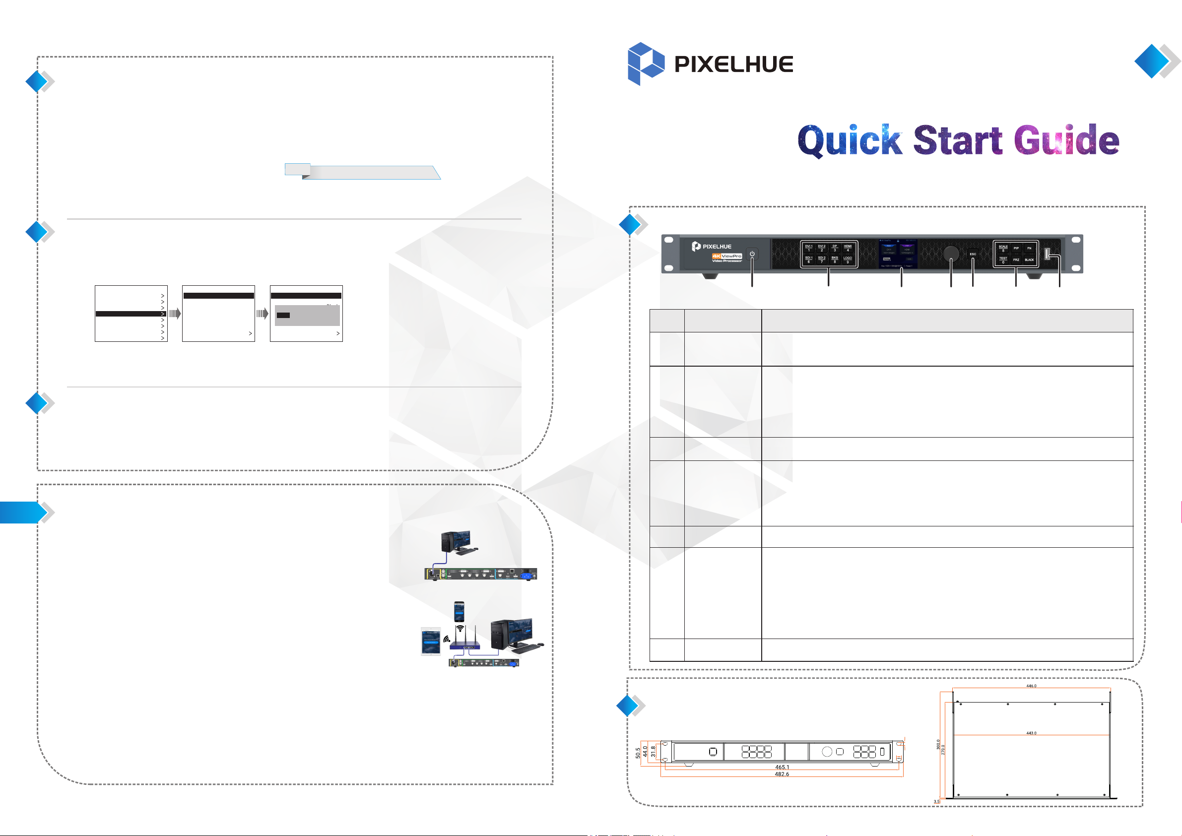
Front Panel
Press the button to turn on the device.
Press the buttonandselectYesontheTFTscreentoturnoffthedevice.
Display signal statuses of input sources and switch input sources quickly.
Button indicator descriptions:
ŸGreen: Input source is accessed and in use.
ŸYellow: Input source is accessed but not in use.
ŸOff: No input source is accessed or input source is abnormal.
ŸRed, off after flashing 5s: Input source is not accessed but in use.
Display the current device status and settings menu.
ŸOn the home screen, press the knob to enter the operation menu screen.
ŸOn the operation menu screen, rotate the knob to select a menu item, and press the knob to
confirm the selection or enter the submenu.
ŸWhen a menu item with parameters is selected, you can rotate the knob to adjust the parameters.
Please note that after adjustment, you need to press the knob again to confirm the adjustment.
Exit the current menu or cancel the current operation.
ŸSCALE: Enter the image scaling menu.
ŸPIP: Enable/Disable PIP. PIP button indicator descriptions:
©On: PIP is enabled.
©Off: PIP is disabled.
ŸFN: Custom function button (Layer Swap)
ŸTEST: Enter the test pattern menu.
ŸFRZ: Freeze the display.
ŸBLACK: Make the display blackout.
For device update and importing preset/BKG/LOGO files.
Dimensions
Before adding a BKG or LOGO image, please firstly import the BKG or LOGO images into the device. The procedure of adding a
LOGO image is the same as that of adding a BKG image. Here take BKG image to illustrate.
On the main menu screen, rotate the knob to choose Layer Settings > BKG > Status, then press the knob and rotate the knob again
to select ON.
On the BKG screen, rotate the knob to select Type, then press the knob and rotate the knob again to select the BKG type.
ŸWhen Image is selected, go to .Step 3
ŸWhen Pure Color is selected, go to .Step 4
Rotate the knob to select Image BKG, then press the knob and rotate the knob again to select Image.
Rotate the knob to select Pure Color BKG, then press the knob to set a pure color by adjusting the R, G and B values individually.
Step 1
Step 2
Step 3
Step 4
Note: LOGO only supports image.
Step 1
Step 2
Step 3
On the main menu screen, rotate the knob to select Preset Settings, then press the knob to enter the preset screen.
Rotate the knob to select a saved preset name and press the knob to enter the preset loading screen.
Rotate the knob to select Load, then press the knob to load the current preset to the screen.
Step 1
Step 2
Step 3
Adding BKG/LOGO
Loading Presets
Saving Presets
Web Operations
The 4K ViewPro supports Web operations
through PC or mobile terminals. You can set
the device-related parameters by using an
Internet browser. The settings are the same
with menu operations.
Recommended browsers:
ŸChrome 50 or above
Ÿ Safari 10 or above
Ÿ Firefox 45 or above
Ÿ Internet Explorer 10.0 or above
Note:
When a PC or mobile terminal is used to
control the device, the front panel buttons
will be locked and a lock icon will appear
on the front panel screen.
Connections
Web connection can be established via two ways.
ŸEthernet cable
Connect the Ethernet port of the control PC with
that of the device with a RJ45 cable.
ŸRouter
©Connect the Ethernet port of the device with a
LAN port of the router, and connect the
Ethernet port of the control PC with a LAN
port of the router.
©Connect the mobile terminals to the router
through WiFi network.
Open one of the recommended browser and type " ". Then http:// the device IP address
press the Enter key to automatically jump to the device Web control page.
Web page is easier to use. The parameters, value ranges of parameters and functions are
all the same with that of in device menu, but the operation methods vary.
For specific Web menu operations, please refer to .4K ViewPro User Manual
Web Interface
Control PC
RJ45
Rotate the knob to select a preset name and press the knob to enter the preset options screen.
Rotate the knob to select Save, then press the knob to save the current settings to the selected preset.
Preset.Sct2
Preset.Sct3
Preset.Sct4
......
Preset.Sct15
Preset.Sct16
Preset Import
Preset Export
Preset Settings
Preset.Sct1
Saved
Saved
......
Blank
Blank
Blank
Blank
Preset.Sct2
Preset.Sct3
Preset.Sct4
......
Preset.Sct15
Preset.Sct16
Preset Import
Preset Export
Preset Settings
Preset.Sct1
Saved
Saved
......
Blank
Blank
Blank
Blank
Output Settings
Layer Settings
Preset Settings
Display Control
General Settings
Communication Settings
Language
Main Settings
Input Settings
Save Load Clear Copy To
RJ45 Control PC
123456
7
6.3
9.8


