Pixsys TCT101-2ABC User manual

TCT101-2ABC
User manual - Manuale uso
Counter - Contatore


User manual - TCT101-2ABC - 3
Table of contents
1 Safety standards.........................................................................................5
2 Model Identification .................................................................................5
3 Technical data..............................................................................................6
3.1 General Features..............................................................................6
3.2 Hardware Features..........................................................................6
3.3 Software Features ...........................................................................7
4 Dimensions and Installation..................................................................7
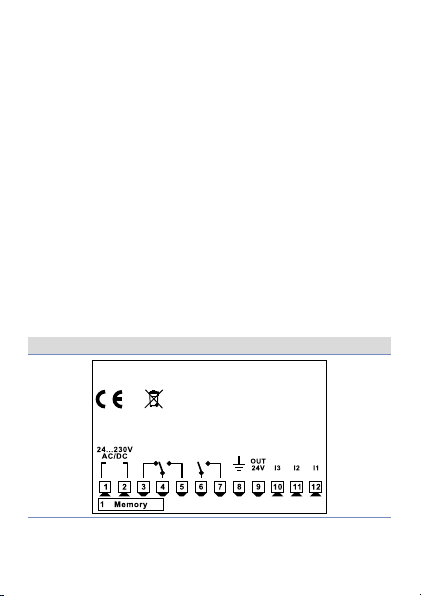
5 Electrical wirings........................................................................................8
5.1 Wiring diagram.................................................................................8
6 Display and keys functions...................................................................11
6.1 Numeric indicators (display).....................................................11
6.2 Meaning of status lights (Led)..................................................11
6.3 Keys .....................................................................................................12
7 Setpoint modification............................................................................12
8 Controller functions................................................................................13
8.1 Memory Card (optional).............................................................13
8.2 Edit parameter configuration...................................................14
8.3 Loading default values................................................................15
9 Table of configuration parameters ...................................................15
9.1 Counter 1...........................................................................................18
9.2 Contatore 2 ..................................................................................... 22
10 Graphs on the counter counting mode......................................... 26
11 Counter operation graphs................................................................... 30
12 Table of Anomaly Signals..................................................................... 34

4 - TCT101-2ABC - User manual
Indice dei contenuti
1 Norme di sicurezza................................................................................. 37
2 Identificazione di modello.................................................................. 37
3 Dati tecnici................................................................................................. 38
3.1 Caratteristiche generali ............................................................. 38
3.2 Caratteristiche Hardware.......................................................... 38
3.3 Caratteristiche software............................................................ 39
4 Dimensioni e installazione.................................................................. 39
5 Collegamenti elettrici............................................................................ 40
5.1 Schema di collegamento........................................................... 40
6 Funzione dei visualizzatori e tasti .................................................... 43
6.1 Indicatori numerici (display).................................................... 43
6.2 Significato delle spie di stato (Led) ....................................... 43
6.3 Tasti .................................................................................................... 44
7 Modifica del Setpoint............................................................................44
8 Funzioni del regolatore........................................................................ 45
8.1 Memory Card (opzionale).......................................................... 45
8.2 Modifica parametro di configurazione................................ 46
8.3 Caricamento valori di default.................................................. 47
9 Tabella parametri di configurazione............................................... 47
9.1 Contatore 1 ..................................................................................... 50
9.2 Contatore 2 ..................................................................................... 55
10 Grafici modalità di conteggio del contatore................................ 59
11 Grafici modalità di funzionamento del counter......................... 63
12 Tabella segnalazioni anomalie .......................................................... 66

User manual - TCT101-2ABC - 5
Introduction
Thanks for choosing a Pixsys device. TCT101 can be set
in 2 different modes: Single or Double counter, all with
independent setting.3 universal digital inputs are available
(NPN / PNP / Potential free contact) and can be used for
bidirectional encoders reading, UP / DOWN counter function,
LOCK / HOLD to lock or hold current visualization. One input
is also analogue in order to allow setpoint modification by an
external potentiometer.
1 Safety standards
Carefully read the instructions and safety measures in this
manual before using the device. Disconnect power before
performing any interventions on the electrical connections
or hardware settings. Only qualified personnel may use/
perform maintenance in full respect of the technical data and
declared environmental conditions.
Do not dispose of electrical appliances together with
household waste. In compliance with the European Directive
2002/96/EC, waste electrical equipment must be collected
separately for eco-compatible reuse or recycling.
2 Model Identification
TCT101-2ABC 24..230VAC / VDC +/-15% 50 / 60Hz / 2W
3 digital inputs + 2 relays 5 A

6 - TCT101-2ABC - User manual
3 Technical data
3.1 General Features
Display 7 segments LED display: 4 digit 0,52 pollici, 4
digit 0,30 inches
Operating
temperature Temperature: 0-40 °C -Humidity 35..95 uR%
Sealing IP65 front panel (with gasket)
IP30 box, IP20 terminals blocks
Material Polycarbonate UL94V0 self-extinguishing
Weight Approx. 120 g
3.2 Hardware Features
Digital inputs
I1 - I2
Configurable via
software in mode:
NPN
PNP (max 28 VDC)
TTL.
Logical levels:
NPN:
H <4.7V
L > 5.7V
PNP:
H >5.7V
L <4.7V
TTL:
H >2.5V
L <2.0V
I3
Configurable via
software in mode:
PNP
TTL
POT (5..10 Kohm)
Logical levels:
PNP:
H >12 .4V
L <10.2V
TTL:
H >2.5V
L <2.0V
Relay outputs
Q1 - Q2
Configurable
operation via
software.
Contacts:
5A - 230 VAC 1/2HP
for resistive load.

User manual - TCT101-2ABC - 7
Sensor supply
output
OUT 24V
Sensor power supply.
Max. current:
30mA @ 24 VAC
40mA @ 24 VDC
60mA @110..230 VAC
Backup Rechargeable
capacitor
Autonomy approx.
7 days.
3.3 Software Features
Programming
tool Labsoftview 2.6 and later
4 Dimensions and Installation
U1
C1
CN1 16
MEMORY C.121
TCT101
123
Frontal panel cut-out
Dima di foratura
28.5 x 70.5 mm
Suggested thickness
2÷8 mm
Spessore suggerito
77 mm
35 mm
53 mm7
42mm insert
42mm inserimento
Memory Card
CN1
1 6
PIXSYS
Memory Card (optional)
with battery
Cod. MEMORY 2100.30.003
Memory Card (optional)
Cod. MEMORY 2100.30.005
Gasket for 32x74
Guarnizione per 32x74
Cod. 1600.00.082 (optional)
5A 230V
Resistive
1/2HP
Q1
5A 230V
Resistive
1/2HP
Q2
PIXSYS
TCT101-2ABC

8 - TCT101-2ABC - User manual
5 Electrical wirings
This device has been designed and manufactured in
conformity to Low Voltage Directive 2006/95/EC , 2014/35/
EU (LVD) and EMC Directive 2004/108/EC, 2014/30/EU (EMC).
For installation in industrial environments please observe
following safety guidelines:
• Separate control line from power wires.
• Avoid proximity of remote control switches, electroma-
gnetic contactors, powerful engines.
• Avoid proximity of power groups, especially those with
phase control.
• It is strongly recommended to install adequate mains filter
on power supply of the machine where the controller is
installed, particularly if supplied 230Vac.
The controller is designed and conceived to be incorporated
into other machines, therefore CE marking on the controller
does not exempt the manufacturer of machines from safety
and conformity requirements applying to the machine itself.
5.1 Wiring diagram
TCT101-2ABC
5A 230V
Resistive
1/2HP
Q1
5A 230V
Resistive
1/2HP
Q2
PIXSYS
TCT101-2ABC

User manual - TCT101-2ABC - 9
5.1.a Connection of digital inputs
NPN
PNP
12
11
10
9
8
Example of connection of digital inputs
in PNP and NPN mode.
5.1.b Connection of proximity sensors
-
+
I3
I2
I1
12
11
10
9
8
3 wires PNP
Proximity Sensor
OUT
Sensore di
Prossimità PNP
a 3 Fili
Example of connection of a 3-wires
proximity sensor.
+
I3
I2
I1
12
11
10
9
8
2 wires PNP
Proximity Sensor
OUT
Sensore di
Prossimità PNP
a 2 Fili
Example of connection of a 2-wires
proximity sensor.
5.1.c Connection of an encoder
+
I3
I2
I1
12
11
10
9
8
Fase A
Fase B
Fase Z
Positivo
GND
Encoder
Example of connection of an encoder.
The Z signal connection is optional.
If the encoder absorbs more current than
that supplied by the OUT 24V output
according to the supply voltage, it may
be necessary to supply the encoder with
an external power supply.

10 - TCT101-2ABC - User manual
5.1.d Potentiometer connection
10
9
8
Potentiometer 5..10 Kohm
Accuracy 1000 points
Potentiometer:
To modify Set1 or Set2 by external potentiometer follow the
steps below:
1 use potentiometers 5kOhm to 10kohm
2 connect cursor to pin I3; a wrong connection may damage
the potentiometer and lead to lock of the device.
3 accuracy on input is max 1000 points, therefore set the
parameters “Upper limit” and “Lower limit” with a max
difference of 1000 units. (Ex.: LoS1 to 50,0 and u PS1 to
150,0 to modify time value related to Set1 between 50 and
150 with steps of one tenth). Greater differences would
make unstable the less significant digit.
4 To calibrate the scale of potentiometer enter the
configuration mode and select:
Hi n . 3 as Pot
Fi n . 3 as Set1 or Set2
P. t A r as Enable
Exit configuration mode and place potentiometer at
minimum level and press ¶key, then place potentiometer
at max level and press premere §key: the device
automatically exit the calibration procedure.
N.B.: a switch-off of the device would interrupt the calibration.

User manual - TCT101-2ABC - 11
6 Display and keys functions
TCT101
123
28 1 7
59 3 4 6
6.1 Numeric indicators (display)
199.59
Normally visualizes the process.
During configuration, visualizes the
parmeter or the group of parameters
which is being entered.
212. 0 0 Normally visualizes the setpoint.
During configuration, visualizes the
parmeter which is being entered.
6.2 Meaning of status lights (Led)
3 1 Report the activation of Q1
42 Report the activation of Q2
5Report serial transmission by the TCT101

12 - TCT101-2ABC - User manual
6.3 Keys
6|
• Allows to visualize command and alarm
setpoints.
• During configuration allows to enter the
parameter to be modified and confirms the
variation.
7!• During configuration works as exit key
(ESCAPE).
8§
• Increases setpoints.
• During configuration allows to scroll the
available parameters, while pressed together
with |it allows to modify the selected
parameter.
9¶
• Decreases setpoints.
• During configuration allows to scroll the
available parameters, while pressed together
with |it allows to modify the selected
parameter.
7 Setpoint modification
Press Effect
1|Display setpoint 1 / 2 (if available)
2§o ¶Modify selected setpoint
3!Select the chosen digit
4§o ¶Modify the flashing digit of the selected
setpoint

User manual - TCT101-2ABC - 13
8 Device functions
8.1 Memory Card (optional)
Parameters and setpoint values can be duplicated from one
device to another using the Memory card.
There are two methods:
• With the device connected to the power supply
Insert the memory card when the device is off.
On activation display 1 shows memo and display 2 show
---- (Only if the correct values are saved in the memory
card). By pressing the §key display 2 shows Lo a d, then
confirm using the !key. The device loads the new data
and starts again.
• With the device not connected to power supply.
The memory card is equipped with an internal battery with
an autonomy of about 1000 operations. Insert the memory
card and press the programming button. When writing
the parameters, the led turns to red and on completing
the procedure it turns to green. It is possible to repeat the
procedure without any particular attention.
Updating Memory Card
To update the memory card values, follow the procedure
described for the first method, setting display 2 to ---- so as
not to load the parameters on devicei.
Enter configuration level and change at least one parameter.
Exit configuration. Changes are saved automatically.
i If on activation the device does not display memo it means no data
have been saved on the memory card, but it is possible to update values.

14 - TCT101-2ABC - User manual
8.2 Edit parameter configuration
For configuration parameters see paragraph 9.
Press Display Do
1!for 3 s.
Display 1 shows
0000
and 1st digit flashes,
Display 2 shows
pass.
2§or ¶
Modify flashing
digit, press |to
reach the following
digit
Enter password:
1234
3|for
confirm
Display shows first
parameter of Fu n c
configuration table.
4§or ¶Scroll the
parameters
5|+ §or ¶
Increase or decrease
value on display by
pressing |and one
of the arrow keys at
same time
Enter new data
which will be stored
releasing the keys.
To modify another
parameter, back to
step 4.
6!
End of configuration,
the device exits
programming mode.

User manual - TCT101-2ABC - 15
8.3 Loading default values
This procedure allows to restore factory settings of the device.
Press Display Do
1!for 3 s.
Display 1 shows
0000
and 1st digit flashes,
Display 2 shows
pass.
2§or ¶
Modify the flashing
digit and move
to the next one
pressing SET.
Enter password
9999.
3|for
confirm
End of configuration,
the device exits
programming mode.
Switch Off and
restart the device
9 Table of configuration parameters
9.a
Function configuration
1
Fu n c.
Counter Function
Counter operating modes
si n g . 1 counter functioning. Default.
doub. 2 counters functioning
9.b
Backup memory configuration
2
p. o . m e .
Power-off memory
Power-off memory
di s . Disabled. No counter stored at power-off.
Default.
cn t .1 Counter 1 stored at power-off
cnt.2 Counter 2 stored at power-off
all All counters stored at power-off

16 - TCT101-2ABC - User manual
9.c
Inputs configuration
3
H .i n . 1
Hardware Input 1
Input 1 Hardware configuration
n pn NPN
pn p PNP. Default.
ttL TTL
4
H .i n . 2
Hardware Input 2
Input 2 Hardware configuration
n pn NPN
pn p PNP. Default.
ttL TTL
5
H .i n . 3
Hardware Input 3
Input 3 Hardware configuration
pn p PNP. Default.
ttL TTL
pot.
Potentiometer
6
fi L . 1
Filter Delay Input 1
Input 1 digital filter configuration
0 . 0 Input filter disabled. Default.
0.5 0,5 ms filter (0,5 ms Step)
... ...
10 0. 0 100,0 ms ms filter
7
fi L . 2
Filter Delay Input 2
Input 2 digital filter configuration
0 . 0 Input filter disabled. Default.
0.5 0,5 ms filter (0,5 ms Step)
... ...
10 0. 0 100,0 ms ms filter

User manual - TCT101-2ABC - 17
8
fi L . 3
Filter Delay Input 3
Input 3 digital filter configuration
0 . 0 Input filter disabled. Default.
0.5 0,5 ms filter (0,5 ms Step)
... ...
10 0. 0 100,0 ms ms filter
9
a .i n . 1
Active State Input 1
Active state input 1
Ri s i . Rising edge. Default.
fa ll. Falling edge
10
a .i n . 2
Active State Input 2
Active state input 2
H . Lev . High level
L. Lev . Low level
Ri s i . Rising edge. Default.
fa ll. Falling edge
11
a .i n . 3
Active State Input 3
Active state input 3
Ri s i . Rising edge. Default.
fa ll. Falling edge
12
F.i n . 3
Function Input 3
Function associated to input 3
di s . Disabled
enc. 2 Loading encoder Z
ld.1 Loading counter 1. Default.
ld . 2 Loading counter 2
ld .1. 2 Loading counters 1 and 2
s et1 Set1 setting by potentiometer
set2 Set2 setting by potentiometer

18 - TCT101-2ABC - User manual
13
F. k. u p
Function Key UP
Additional functionality on § key
di s . Disabled. Default.
ld.1 Loading counter 1
ld . 2 Loading counter 2
ld .1. 2 Loading counters 1 and 2
14
p. t a r.
Potentiometer tarature
Potentiometer calibration procedure
di s . Disabled. Default.
En. Enabled
9.1 Counter 1
9.1.a
Counter clock configuration
15
cl.c.1
Clock Counter 1
Counter 1 count mode selection. (refer to paragraph 10
for counter modes).
di s . Disabled
enc. Bidirectional encoder (I1) phase A, (I2) phase B
u p.-- UP mode (I1). Default.
d o .-- DOWN mode (I1)
--. u p UP mode (I2)
--. d o . DOWN mode (I2)
u p. d o . UP mode (I1) - DOWN mode (I2))
u p.i . d . UP mode (I1) with reverse direction (I2)
u p. e. l . UP mode (I1) with count lock (I2)
u p. e . H . UP mode (I1) with keeping value on display (I2)
do. e.l. DOWN mode (I1) with count lock (I2)
do. e. H. DOWN mode (I1) with keeping value on
display (I2)
o.c.2 UP count on rising edge of counter 2 output

User manual - TCT101-2ABC - 19
9.1.b
Counter display configuration
16
di . C . 1
Display Counter 1
Counter 1 visualization selection
di s . Disabled. Counter value non visualized.
Wi s u . Counter value visualized. Default.
17
d . p. C.1
Decimal Point Counter 1
Counter 1 visualization format
0No decimal digit visualization. Default.
0.0 1 decimal digit visualization
0.00 2 decimal digits visualization
0.000 3 decimal digits visualization
18
in.C.1
Counter 1 input counts
Counter 1 input counts (1..9999). Default 1.
19
vi . C . 1
Counter 1 visualized counts
Counter 1 visualized counts (1..9999). Default 1.
9.1.c
Setpoint configuration
20
di . s . 1
Display Set 1
Counter 1 setpoint visualization selection
di s . Disabled.
Wi s u . Setpoint value visualized
M o di . Setpoint value visualized and editable.
Default.
21
Lo . s .1
Lower Limit Set 1
Set 1 minimum value (0..9999). Default 0.
22
u p. s . 1
Upper Limit Set 1
Set 1 maximum value (0..9999). Default 999.

20 - TCT101-2ABC - User manual
9.1.d
Automatic load configuration
23
a.l.C.1
Automatic Load Counter 1
Automatic counter loading 1
di s . Disabled
s et1 Loading if counter = Set1. Default
set2 Loading if counter = Set2
s. o. d.1
Loading if counter = Set1 + “Output Duration 1”
s.o.d.2
Loading if counter = Set2 + “Output Duration 2”
vi . C . 1 Loading if counter = “Visualized Counts”
s.-d.1
Loading if counter = Set1 - “Output Duration 1”
s.-d. 2
Loading if counter = Set2 - “Output Duration 2”
s. d. t.1 Loading if counter = Set1 “Output Duration 1”
s.d.t.2 Loading if counter = Set2 “Output Duration 2”
9.1.e
Counter load value configuration
24
C.L.d.1
Counter 1 Load Value
Counter 1 loading value. Default 0.
9.1.f
Counter output mode configuration
25
C.o. M.1
Counter 1 Output Mode
Counter 1 output mode (refer to paragraph 11 for the
operation graphs).
set.1 Output active if Counter ≥ Set. Default
ti m e Output active for “Output Duration” time if
Counter ≥ Set
Count. Output active for “Output Duration” counts if
Counter ≥ Set
se.1. 2 Output active if Counter ≥ Set1+Set2
-se.1 Output active if Counter ≤ Set
- ti m . Output active for “Output Duration” time if
Counter ≤ Set
-Co u . Output active for “Output Duration” counts if
Counter ≤ Set
-s .1. 2. Output active if Counter ≤ Set1+Set2
Table of contents
Languages: