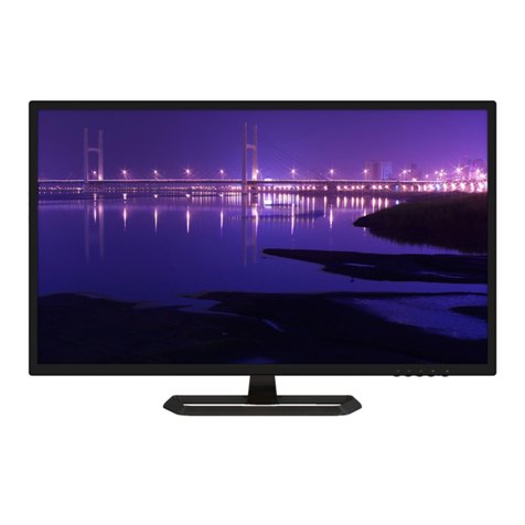
Planar PE2010 User manual

20" LCD Color Monitor Planar PE2010
1
Service
Service
Service
HorizontalFrequency
30-82kHz
TABLE OF CONTENTS
Description Page Description Page
SAFETY NOTICE
ANY PERSON ATTEMPTING TO SERVICE THIS CHASSIS MUST FAMILIARIZE HIMSELF WITH THE CHASSIS
AND BE AWARE OF THE NECESSARY SAFETY PRECAUTIONS TO BE USED WHEN SERVICING ELECTRONIC
EQUIPMENT CONTAINING HIGH VOLTAGES.
Table Of Contents.......……..............................…........1
Revision List.…........................................……......2
1. Monitor Specification..............................………........3
2. LCD Monitor Description…………………………….......4
3. Operation Instruction…………...............……...........4
3.1. General Instructions...........................…...........4
3.2. Control Buttons.……….…..............……...............5
3.3 Adjusting the Picture...........................…............6
4. Input/Output Specification............……………............9
4.1. Input Signal Connector............………….................9
4.2. Factory Preset Display Modes......…..................10
4.3. Power Supply Requirements...............................10
5. Panel Specification.....………………..................11
5.1. General Feature…….....………………..................11
5.2. Optical Characteristics………………………………12
6. Block Diagram……...................…………................13
6.1 Monitor Exploded View…………………....….......13
6.2 Software Flow Chart………………………….14
6.3. Electrical Block Diagram……………..….......16
7. Schematic……………......................................18
7.1 Main Board....……….......................................18
7.2 Power Board.….……....................................23
7.3 Key Board………………….……………………25
8. PCB Layout..………….......................................26
8.1. Main Board………........................................26
8.2. Power Board….......................................29
8.3. Key Board………............….......................31
9. Maintainability……….......................................32
9.1. Equipments and Tools Requirement..............32
9.2. Trouble Shooting………..............................33
9.2.1 Main Board…………..............................33
9.2.2 Power Board………..............................36
9.2.3 Key Board…………..............................38
10.White-Balance, Luminance adjustment……....39
11. BOM List……...…………………………………41
CAUTION: USE A SEPARATE ISOLATION TRANSFOMER FOR THIS UNIT WHEN SERVICING

20" LCD Color Monitor Planar PE2010
2
Revision List
Version Date Revision History TPV Model Name
A00 Jul.-14-06 Initial release TA5MM6NKEDPNNP
A01 May.-04-07 Second Release TA6MM6NKEDPNN

20" LCD Color Monitor Planar PE2010
3
1. Monitor Specification
Items Description
Driving system TFT Color LCD
Size 51cm (20”)
Panel M201P1-L01
Display area 408.24(H) x306.18 (V)
Pixel pitch 0.2916mm(H) x 0.2916mm(V)
Viewable angle 160˚(H) 160˚(V)
Response time (typ.) 8ms
Brightness 300cd/m²
LCD Panel
Contrast 700:1
R,G,B Analog Interface
Video
Digital Interface
H-Frequency 30kHz – 82kHz
Input
V-Frequency 60-75Hz
Display Colors 16.2M
Dot Clock (max.) 162MHz
Max. Resolution 1400 x 1050 @60 Hz
Plug & Play VESA DDC1/2BTM
ON Mode ≤41W
Power Consumption
OFF Mode ≤1W
Weight(N.W.) 6kg Unit(net)
Dimensions 445.6(W) x 160(H) x 417.6(D)mm
Power Source 100~240VAC,47~63Hz
Environmental
Considerations
Operating Temp: 0°C to 35°C
Storage Temp.: -20°C to 60°C
Operating Humidity : 10% to 85%

20" LCD Color Monitor Planar PE2010
4
2.LCD Monitor Description
The LCD Monitor will contain main board, power board, and key board which house the flat panel control logic,
brightnesscontrollogicandDDC.
The power board will provide AC to DC Inverter voltage to drive the backlight of panel and the main board chips each
voltage.
3. Operation Instructions
3.1 General Instructions
Press the power button to turn the monitor on or off. The other control buttons are located at front of the panel. By
changing these settings, the picture can be adjusted to your personal performance.
-The power cord should be connected and insert to adaptor.
-Connect the video cable from the monitor to the computer VGA card.
-Press the power button to turn on the monitor, the power indicator will light up to Green.
Video signal, DDC
Power Board
(
Include ada
p
ter and inverter
)
Flat Panel and
CCFL backlight
Main Board RS232 Connector
For white balance
adjustment in
factory mode
HOST Computer
CCFT Drive.
AC-IN
110V-240V
Monitor Block Diagram
Key board

20" LCD Color Monitor Planar PE2010
5
3.2 Control Buttons
• Power Button:
Press this button to turn the monitor ON or OFF.
• MENU / ENTER:
Active OSD menu or function adjust confirm.
• ∧ / ECO
ECO switching
• ∨ / Bri /Con
Bri /Con adjusting
• Source
Select the VGA or DVI function.

20" LCD Color Monitor Planar PE2010
6
OPERATING INSTRUCTIONS (cont.)
•Auto Adjust button / Exit:
1. When OSD menu is in active status, this button will act as EXIT-KEY(EXIT OSD menu) or go back to the previous
menu.
2. When OSD menu is in off status, press this button for 2 seconds to activate the Auto Adjustment function.
The Auto Adjustment function is used to set the HPos, VPos, Clock and Focus.
•Power Indicator:
Green — Power On mode.
Amber — Standby mode.
•OSD-Lock Function:
Option 1: OSD lock - all 5 buttons are locked except the "POWER" button. Press and hold the "MENU" and "V" buttons
for 3 seconds to lock the buttons. Repeat this step to unlock.
Option 2: OSD & Power button lock - all 6 buttons including the
"POWER" button are locked. Press and hold the "MENU" and"∧" buttons for 3 seconds to lock all 6 buttons. Repeat
this step to unlock."
3.3 Adjust the Picture

20" LCD Color Monitor Planar PE2010
7

20" LCD Color Monitor Planar PE2010
8

20" LCD Color Monitor Planar PE2010
9
4. Input/Output Specification
4.1 Input Signal Connector
Analog connector
Pin Signal Pin Signal
1 Red Video 9 +5 V
2 Green Video 10 Detect Cable
3 Blue Video 11 None
4 None 12 DDC-Serial Data
5 Ground (DDC Return) 13 Horizontal Sync
6 Red GND 14 Vertical Sync
7 Green GND 15 DDC-Serial Clock
8 Blue GND
15 - Pin Color Analog Signal Cable
VGA connector layout
PIN 1 PIN 5
PIN 11
DVI-D Connector
Pin No. Description Pin No. Description
1. TMDS Data 2-13. TMDS Data 3+
2. TMDS Data 2+14. +5V Power
3. TMDS Data 2/4 Shield 15. Ground (for +5V)
4. TMDS Data 4-16. Hot Plug Detect
5. TMDS Data 4+17. TMDS Data 0-
6. DDC Clock 18. TMDS Data 0+
7. DDC Data 19. TMDS Data 0/5 Shield
8. N.C. 20.
TMDS Data 5-
9. TMDS Data 1-21. TMDS Data 5+
10. TMDS Data 1+22. TMDS Clock Shield
11. TMDS data 1/3 Shield 23. TMDS Clock +
12. TMDS Data 3-24. TMDS Clock -
24 - Pin Color Display Signal Cable

20" LCD Color Monitor Planar PE2010
10
4.2 Factory Preset Display Modes
Standard Resolution Horizontal Frequency(KHZ) Vertical Frequency(HZ)
IBM DOS 720 × 400 31.47 70.0
640 × 480 31.47 60.0
VGA
640 × 480 37.50 75.0
800 × 600 37.879 60.0
SVGA
800 × 600 46.875 75.0
1024 × 768 48.363 60.0
1024 × 768 56.476 70.0
1024 x 768 60.02 75.0
1024 x 768 48.780 60.0
VESA
XGA
1024 x 768 60.241 75.0
1280 × 1024 64.00 60.0SXGA
1280 × 1024 80.00 75.0
SGXA 1400 x 1050 75.00 60.0
4.3 Power Supply Requirements
A/C Line voltage range : 100 V ~ 240 V ±10%
A/C Line frequency range : 50 ±3Hz, 60 ±3Hz
Current : 5.0A max
Peak surge current : < 55A peak at 240 VAC and cold starting
Leakage current : < 3.5mA
Power line surge : No advance effects (no loss of information or defect)
with a maximum of 1 half-wave missing per second
DC output Voltage : 5VDC ± 5%; 12VDC± 5%
CURRENT 2Amp (5V) ;3Amp (12V)

20" LCD Color Monitor Planar PE2010
11
5. Panel Specification
5.1 General Feature
Mechanical Information

20" LCD Color Monitor Planar PE2010
12
5.2 Optical Characteristics
Test Conditions
Optical Specification

20" LCD Color Monitor Planar PE2010
13
6. Block Diagram
6.1 Monitor Exploded View
.

20" LCD Color Monitor Planar PE2010
14
6.2 Software Flow Chart
1
2
N
Y
5
Y
N
10
Y
N
12
Y
N
7
Y
N
6
4
3
8
9
14
11
13
Y
N
15
Y
N
16
17
19
Y
N
18

20" LCD Color Monitor Planar PE2010
15
REMARK:
1) MCU initialize.
2) Is the EEprom blank?
3) Program the EEprom by default values.
4) Get the PWM value of brightness from EEprom.
5) Is the power key pressed?
6) Clear all global flags.
7) Are the AUTO and SELECT keys pressed?
8) Enter factory mode.
9) Save the power key status into EEprom.
Turn on the LED and set it to green color.
Scalar initialize.
10) In standby mode?
11) Update the lifetime of back light.
12) Check the analog port, are they’re any signals coming?
13) Does the scalar send out an interrupt request?
14) Wake up the scalar.
15) Are there any signals coming from analog port?
16) Display "No connection Check Signal Cable" message. And go into standby mode after the message
disappear.
17) Program the scalar to be able to show the coming mode.
18) Process the OSD display.
19) Read the keyboard. Is the power key pressed?

20" LCD Color Monitor Planar PE2010
16
6.3 Electrical Block Diagram
6.3.1 Scalar Board
Serial Flash
U402
Reset IC
U406
Analog-EDID
U404
Digital-EDID
U405
NVRAM – 24C16
U403
DSUB CN405
DVI CN406
SCALAR –TSUM56AK-1
U401
Crystal X401
14.318MHz
DDC-DVI port
DDC-DSUB port
CN404 to Audio Board
CN403 to Keyboard
To Inverter Block
CN101
To Panel
Panel Power
sequence control
circuit ( block
Q708,Q706 , Q704)
Brightness control
LVDS output
A/D input control
Power input
( from power board)
CN701
LDO U701,U702
Transistor Q702
3.3V
1.8V
SCL , SDA ,WP
SCL , SDA ,WP
RGB, H/V SYN
TMDS

20" LCD Color Monitor Planar PE2010
17
6.3.2 Inverter / Power Board

20" LCD Color Monitor Planar PE2010
18
7. Schematic
7.1 Main Board
VCC5V
VLCD
+12V
XGA/SXGA
+12V
TSUM57AK SCHEMATIC
715G1558-1-ao.DSN
B
TOP
B
26Friday, October 21, 2005
Title
Size Document Number Rev
Date: Sheet of
+5V
PA[8..13]
VLCD
PC5V
B2
2.POWER
on_Panel
on_BACKLIGHT
Adj_BACKLIGHT
+3V3
VCC1.8
VLCD
+5V
VCTRLPC5V
VCC5V
VCC3.3
on_PANEL_12V
VLCD_12V
+12V
B3
3.INPUT
RIN
GIN
BIN
VSYNC
GNDR
GNDG
GNDB
DET_VGA
HSYNC
SOG
B+
CLK-
DET_DVI
CLK+
R+
G+
R-
B-
G-
DDCA_SDA
DDCA_SCL
DDCD_SDA
DDCD_SCL
+5V
DDC_WP
VCC1.8
PB[6..11]
B5
5.PANEL INTERFACE
VLCD
PA[0..7]
PA[8..13]
ESP
PA[14..19]
PB[0..5]
PB[6..11]
GPO[0..4]
OSP
VLCD_12V
PB[12..23]
VCC3.3
PB[0..5]
VCC3.3
LVDS OUTPUT
PB[12..23]
PA[14..19]
+3V3
+5V
B4
4.SCALER
RIN
GIN
SOG
BIN
GNDR
GNDG
GNDB
HSYNC
VSYNC
Adj_BACKLIGHT
VCC1.8
Vcc3.3
VCTRL
PA[0..7]
PA[8..13]
R+
R-
G-
G+
B+
B-
CLK+
CLK-
DDCD_SDA
DDCD_SCL
DET_DVI
DDCA_SDA
DDCA_SCL
DET_VGA
on_BACKLIGHT
on_Panel
+5V
PA[14..19]
PB[0..5]
PB[6..11]
GPO[0..4]
ESP
OSP
on_PANEL_12V
PB[12..23]
+12V
DDC_WP
PA[0..7]
VLCD_12V
VLCD_12V
GPO[0..4]
VCC1.8
+5V

20" LCD Color Monitor Planar PE2010
19
R726 NC/4K7
4K7
0V ~ 3.3V
PC5V
VCC3.3
C706
0.1uF
12/21 MODIFY
R729
NC/10K
VLCD 5
0V ~ 5V
+3V3
C720
NC/0.1uF
R735
4.7K 1/16W
C715
0.1uF
+3V3
R710 NC
715G1558-1-ao.DSN
B
Power
Custom
36Friday, October 21, 2005
Title
Size Document Number Rev
Date: Sheet of
R727
10K 1/16W
VCC3.3
Q709
NC/PMBS3904
Q706
PMBS3904
+5V3,4
TO-263
+
C719
NC/10uF/16V
+5V
Q701
PMBS3904
R31
R719
NC/10K
+5V3,4
+
C705
1uF/16V
R734
10K 1/16W
R705 4.7K 1/16W
D701
1N4148
R33
+12V
D702
1N4148
VCTRL 4
D704(SSM12L) Vf=0.38V and If=1A.
So when system power on, the
system loading is about 400mA
(3.3V is about 200mA and 1.8V is
about 200mA), So D35 changed
from 1N4148(or BAT42) to
SSM12L(schottky diode).
BL_ADJ
+12V
C701
NC
R707
4.7K 1/16W
GND
R716
NC
+5V3,4
R731
NC
C722
NC/0.1uF
C716
0.1uF
BL_ADJ
P.S: The 1N4148 Vf=0.7V~1V can't meet
LDO spec. The BAT42, Vf is OK but the
If=200mA(forward current) can not
meet current spec.
C718
0.1uF
+
C707
100uF/25V
+5V
VCC1.8
+
C702
4.7uF/16V
R737 NC/4K7
VCC3.3 4
X
GND
Q703
PMBS3904
R725
4.7K 1/16W
P W M
10/20/2005 : For Panel Protection. Add Q708, Q709, R733~R737, C721~C722
D703
BAT54C
3
1
2
4.7K
GND
CN701
CONN
2
4
6
8
10
12
1
3
5
7
9
11
R713
NC
+3V3
GND
R704
100 1/16W
D C
MMBT3904
R733
NC
R708
10K 1/16W
R722
NC
PC5V 3
+5V
+12V 4
Q708
PMBS3904
D704
SMAL140
R32
+5V
Q707
NC/PMBS3904
VLCD
H1
TP
1
2
3
4
5
6
7
8
9
1
2
3
4
5
6
7
8
9
+
C712
100uF/25V
BL_ON
Q702
CHT2907
C
B
E
+5V
+5V
R701
1K 1/16W
R714
10K 1/16W
0
+5V
R728
NC/4K7
R712 4.7K 1/16W
R706 NC
R717
10K 1/16W
+3V3
VCC5V
R711
10K 1/16W
C704
NC
H2
TP
1
2
3
4
5
6
7
8
9
1
2
3
4
5
6
7
8
9
R732
10 1/16W
C721
0.1uF
N.C
+
C703
100uF/25V
+5V
+
C710
100uF/25V
R29
GND
R721
0 1/16W
VCC3.3 4
For RSDS and Panel VCC=12V
4.7K X
SOT-223
on_Panel4
R31
R703
2K 1/16W
Recommond to used "Blue" parts circuit
for VCC1.8V if you want to suppoert DDC
function when system power off
+3V3
R718
NC/10K
X
R723 51K 1/16W
R724 51K
VCC1.8 4
U702
AIC1084-33PM
3
1
2
4
VIN
ADJ
VOUT
VOUT
+5V
VLCD_12V 5
C32
1K 4.7K
1uF
+12V
U701
NC/LT1117-18
3 2
1
4
VI VO
GND
VO
C714
0.1uF
C713
0.1uF
Adj_BACKLIGHT
4
47
+12V
+12V
R736
NC/10K
X
R730
0 1/16W
on_BACKLIGHT 4
+5V
VLCD_12V
+5V
C708
1uF
1UF
+5V
C51
C709
0.1uF
on_Panel_12V4
Q705
AO3401L
R709
0 1/16W
1UF
C711
0.1uF
+
C717
10uF/16V
GND
R715
NC
BL_ADJ(DC)
+5V
H3
TP
1
2
3
4
5
6
7
8
9
1
2
3
4
5
6
7
8
9
Q4
R702
51 1/16W
Q704
AO3401L
R720 0 1/16W

20" LCD Color Monitor Planar PE2010
20
SCL_DVI
R434 56 1/16W
D423
BAV99
3
1
2
DDCA_SCL4
D403
BAV99
3
1
2
R452
10K 1/16W
D421
BAV99
3
1
2
R459
10K 1/16W
R439
75 1/16W
SDA_DVI
D420
BAV99
3
1
2
BIN 4
PC5V
C437 0.047uF
R461
10K 1/16W
C439 0.1uF
R446 1K 1/16W
R- 4
R460
10K 1/16W
R444
10K 1/16W
C450
0.1uF
FB412 0 1/16W
HPD
C447
0.1uF
GREEN-
DVI5V
+5V
D424
BAV99
3
1
2
C445
0.1uF
R456 100 1/16W
R445 100 1/16W
FB410 0 1/16W
B- 4
VSI
R448
2.2K 1/16W
GREEN+
C449
0.1uF
C433 0.047uF
DET_DVI 4
C442
33pF
GIN 4
CN405
DB15
1
6
2
7
3
8
4
9
5
11
12
13
14
15
10
1716
D410
MLL5232B 5.6V
DAT0-
D413
BAV70
3
1
2
DET_VGA 4
BLUE-
CLK+ 4
D416
LL5232B 5.6V 5%
D412
MLL5232B 5.6V
ESD_5V
C454
0.1uF
DCLK-
R468 10 1/16W
BLUE+
C443
220pF
R465 10 1/16W
+5V
FB409 120 OHM
D406
MLL5232B 5.6V
D404
BAV99
3
1
2
C444
0.1uF
D408
MLL5232B 5.6V
GNDG 4
R473
NC
DAT1-
R458 100 1/16W
RIN 4
DDC_WP 4
RED+
R438
75 1/16W
PC5V
G+ 4
R443 100 1/16W
DVI5V
D426
LL5232B 5.6V 5%
VGA_CON
C452
0.1uF
DDCD_SDA4
+5V
R453 100 1/16W
R436 56 1/16W
DAT2-
D419
BAV99
3
1
2
DDCD_SCL4
RED-
715G1558-a-ao.DSN
B
INPUT
B
46Friday, October 21, 2005
Title
Size Document Number Rev
Date: Sheet of
D415
LL5232B 5.6V 5%
R469 10 1/16W
D407
BAV70
3
1
2
VCC5V
DAT2+
R451
10K 1/16W
HSYNC 4
SCL_VGA
R464 10 1/16W
U404
M24C02
1
2
3
45
6
7
8A0
A1
A2
GNDSDA
SCL
WP
VCC
R463 10 1/16W
+5V 2,4
C441 0.1uF
R462 10 1/16W
DDC_WP 4
R440
75 1/16W
D405
BAV99
3
1
2
DCLK+
D418
BAV99
3
1
2
VSYNC 4
R455 100 1/16W
C435 0.047uF
CLK- 4
G- 4
R450
10K 1/16W
C436 0.047uF
R435 56 1/16W
D425
RLZ36B
1 2
DAT1+
PC5V
ESD_5V
R466 10 1/16W
GNDB 4
SOG 4
C434 0.047uF
R+ 4
DAT0+
R457 10K 1/16W
D411
MLL5232B 5.6V
U405
M24C02
1
2
3
45
6
7
8A0
A1
A2
GNDSDA
SCL
WP
VCC
DDCA_SDA4
C432 0.047uF
R467 10 1/16W
D414
LL5232B 5.6V 5%
C438 0.047uF
R472
NC
C453
0.1uF
D422
BAV99
3
1
2
+5V
D409
MLL5232B 5.6V
R437 470 1/16W
B+ 4
R449
2.2K 1/16W
R441 100 1/16W
C451
0.1uF
DVI5V
SDA_VGA
R442 100 1/16W
R447 1K 1/16W
GNDR 4
R454 100 1/16W
C448
0.1uF
FB411 0 1/16W
HSI
R470
1K 1/16W
R471
10K 1/16W
CN406
JACK DVI
1
2
3
4
5
6
7
8
25
28
9
10
11
12
13
14
15
16
26
29
17
18
19
20
21
22
23
24
27
DAT2-
DAT2+
2/4shield
DAT4-
DAT4+
DDC SCL
DDC SDA
VSYNC
R
HSYNC
DAT1-
DAT1+
1/3shield
DAT3-
DAT3+
+5V
SYNC GND
HPD
G
RGB GND
DAT0-
DAT0+
0/5shield
DAT5-
DAT5+
clk shield
clk+
clk-
B
C446
0.1uF
C440 0.1uF
D417
BAV99
3
1
2
Other manuals for PE2010
1
Table of contents
Other Planar Monitor manuals

Planar
Planar UltraRes L Series User manual

Planar
Planar PT3270Q User manual

Planar
Planar LA1500R User manual

Planar
Planar LC1200R User manual

Planar
Planar FWT1503Z User manual

Planar
Planar PE191M User manual

Planar
Planar PZN3210U User manual

Planar
Planar LA1500R User manual

Planar
Planar PT1510MX User manual

Planar
Planar EL160.120.39 User manual

Planar
Planar PXN2770MW User manual

Planar
Planar PS Series User manual

Planar
Planar PT1503Z User manual

Planar
Planar SD2620W User manual

Planar
Planar c50RP User manual

Planar
Planar PX191 User manual

Planar
Planar PT1710MX User manual

Planar
Planar LA2250RTPW User manual

Planar
Planar PLN2700 User manual

Planar
Planar PDP42HD User manual