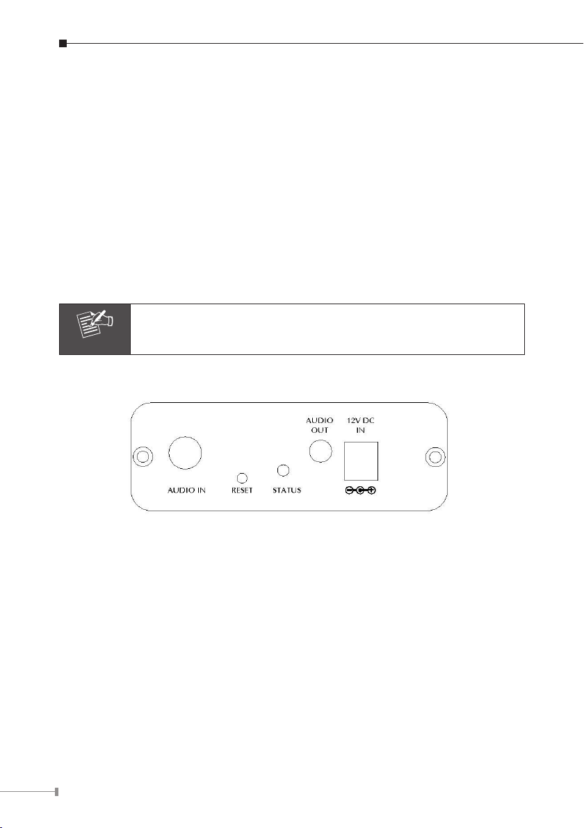
Planet ICA-310 User manual

Internet Camera
&
Internet Video Server
Quick Installation Guide

Table of Contents
Chapter 1. Introduction .................................................................................... 4
1.1 Before Installation .................................................................... 4
1.2 System Requirements for Viewer ............................................... 4
Chapter 2. IVS-110 – 1-Channel Internet Video Server....................................... 5
2.1 Package Content....................................................................... 5
2.2 Physical Installation ................................................................. 5
2.2.1 Front Panel...................................................................... 5
2.2.2 Back Panel ...................................................................... 6
2.2.3 Installation Steps ............................................................. 7
Chapter 3. ICA-310 – 30M Infrared Internet Camera .......................................... 8
3.1 Package Content....................................................................... 8
3.2 Physical Installation .................................................................. 8
Chapter 4. ICA-312 – 25M Infrared Internet Camera .........................................10
4.1 Package Content......................................................................10
4.2 Physical Installation .................................................................10
Chapter 5. ICA-350 – 30M Infrared Internet Camera .........................................11
5.1 Package Content......................................................................11
5.2 Physical Installation .................................................................11
Chapter 6. ICA-525 – 20M IR Vandal Proof Dome Internet Camera.....................13
6.1 Package Content......................................................................13
6.2 IdenticationofCables.............................................................13
6.3 Physical Installation .................................................................14
Chapter 7. ICA-530 – 15M IR Dome Internet Camera........................................18
7.1 Package Content......................................................................18

7.2 IdenticationofCables.............................................................18
7.3 Physical Installation .................................................................20
Chapter 8. IPwizard Installation and operation ..................................................21
8.1 IPwizard Installation.................................................................21
8.2 Wizard function .......................................................................24
8.3 Username and Password .........................................................25
Chapter 9. Cam Viewer Installation ..................................................................26
Appendix A: Feature Listing for Cam Viewer ....................................................30
Appendix B: Suggest Hardware / System Requirement ......................................31

4
Chapter 1. Introduction
Thank you for purchasing the IP surveillance product. It is versatile and high image
solution of the perfect indoor / outdoor surveillance application. The IP surveillance
state-of-artdesignisconsiderabletotinvariousnetworkenvironments.
1.1 Before Installation
Before installation, please be sure to read this quick installation guide and user’s
manual (CD) carefully to complete machine installation.
This QIG includes the following chapter:
• Chapter2. IVS-110 – 1-Channel Internet Video Server
• Chapter3. ICA-310 – 30M Infrared Internet Camera
• Chapter4. ICA-312 – 25M Infrared Internet Camera
• Chapter5. ICA-350 – 30M Infrared Internet Camera
• Chapter6. ICA-525 – 20M IR Vandal Proof Dome Internet Camera
• Chapter7. ICA-530 – 15M IR Dome Internet Camera
• Chapter8. Initial Utility Installation and operation
• Chapter9. Cam Viewer Installation
• Appendix A: Feature Listing for Cam Viewer
• Appendix B: Suggest Hardware / System Requirement
1.2 System Requirements for Viewer
Network
Interface 10/100MBase-TX Ethernet
Monitoring
System Recommended for Internet Explorer 6.0 or later
System
Hardware
●CPU:Pentium4,1.5GHzorabove
●MemorySize:512MB(512MBoraboveRecommended)
●VGAcardresolution:1024x768orabove
●SoundCard:Necessary
●Network bandwidth: In VGA resolution mode, mini-
mum upload bandwidth is 1Mbps.

5
Chapter 2. IVS-110 – 1-Channel Internet Video Server
2.1 Package Content
IVS-110 x 1
Power Adapter x 1
PowerCablex1
CD Disk x 1
Quick Installation Guide x 1
Note
1.Ifanyoftheaboveitemsaremissing,pleasecontactyourdealer
immediately.
2. Using a power supply with a different voltage that the one
included with the IVS-110 will cause damage and void the
warranty for IVS-110.
2.2 Physical Installation
2.2.1 Front Panel
LAN Socket
The LAN socket is a RJ-45 connector for connections to 10Base-T Ethernet or
100Base-TX Fast Ethernet cabling. This Ethernet port built N-Way protocol can
detect or negotiate the transmission speed of the network automatically. Please
useCategory5“straightthrough”cabletoconnecttheIVS-110toa100MbpsFast
Ethernet network switch or hub. The LAN socket is compliant with IEEE802.3af
standard PoE interface.
Note
1. If you need to connect the IVS-110 to PC or notebook directly,
youshouldusecrossovercableinstead.
2. PoE and DC adapter only can select one of them

6
Video-in Jack
You can install an analog camera and connect it to video-in jack.
12V DC-Out Jack
The output power is 12V DC. This is used to supply 12V DC power to one external
camera. The output power is 12V DC, 400mA maximum. The output power still
supplies12VDC,400mApowertooneexternal,whentheIVS-110obtainspower
from PoE switch.
DI/DO/RS-485 Connector
This IVS-110 provides a general I/O terminal block with one digital input and one
output for device control. It has 6 Pins that from left to right that are 12V DC
power supply (50mA maximum), Alarm Input, GND, Alarm Output, D+ terminal of
RS-485 and D- terminal of RS-485.
Note
The RS-485 of IVS-110 is master that can control external scanner
or PT camera.
2.2.2 Back Panel
Audio-in Jack
Audio-in (line level) jack allows any device that could input audio.
Reset Button
Thisbuttonishiddeninthe pinhole.PleaserefertotheAppendixAinmanualfor
more information.
Status LED
The Status LED will turn green while system is booting up successfully. This LED
isalsousedtoindicatethestatusofnetworkconnection.TheLEDwillashgreen
while some on access the IVS-110.
Audio-Out Jack
Audio-out Jack allows this device to output audio or alerting sound.

7
12V DC-in Jack
The input power is 12V DC.
Note
Only use the power adapter supplied with IVS-110. Otherwise, the
productmaybedamaged.
2.2.3 Installation Steps
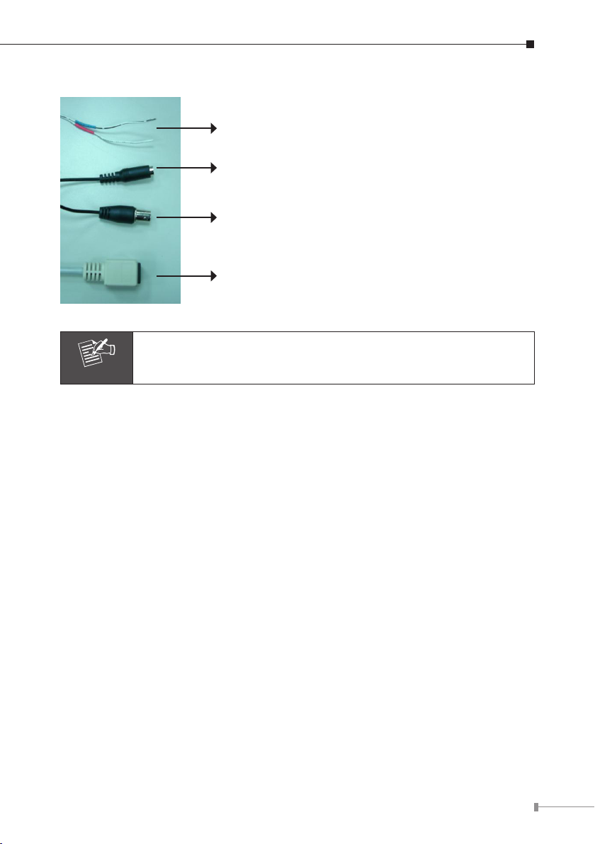
1. Attach video source to IVS-110
To use IVS-110, user must supply video source to IVS-110. Connect the BNC
terminal of camera to the IVS-110’s video input and make sure to power on
camerarst.
2. Attach Audio source to IVS-110 (option)
If user needs not only video stream but also audio stream, then the audio
source should be attached to IVS-110. Connect the RCA terminal of audio de-
vice’s line output to the IVS-110’s RCA input and make sure to power on your
cameraoraudiodevicerst.
3. Plug an Ethernet cable into IVS-110
Connect an Ethernet cable to the LAN socket located on the IVS-110’s panel
and attach it to the network. If there has a PoE switch in your network, you can
connect the IVS-110 LAN cable to this PoE switch to obtain power. The power
adapter is unnecessary when IVS-110 is connected to a PoE switch.
4. Connect RS-485 (option)
When users would like to apply a camera with P/T/Z function, they usually need
to connect their communication port (for camera control) through RS-485. After
RS-485 was correctly connected to D+ and D-, the remote users could control
the camera movement through internet.
5. Connect the external power supply to IVS-110
Plug in power adapter and connect to power source. If there has a PoE switch
in your network, you can connect the IVS-110 LAN cable to this PoE switch to
obtain power. The power adapter is unnecessary when IVS-110 is connected to
a PoE switch. After power on, IVS-110 will start to operate. Once you have in-
stalled the IVS-110 well, the status LED will turn green. It means the system is
booting up successfully. Furthermore, if you have a proper network connection,
andaccesstotheIVS-110,theLEDwillashgreen.
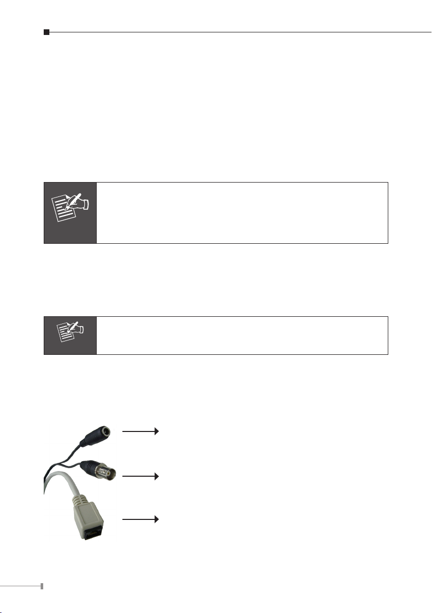
6. Connect the power supply to one external camera (option)
The IVS-110 can provide 12V DC out to supply one external camera. The output
current is 400mA maximum.

8
Chapter 3. ICA-310 – 30M Infrared Internet Camera
3.1 Package Content
ICA-310 x 1
Power Adapter x 1
Wall Mount Accessories x 1
CD Disk x 1
Quick Installation Guide x 1
Note
1.ifanyoftheaboveitemsaremissing,pleasecontactyourdealer
immediately.
2. Using a power supply with a different voltage that the one
included with the ICA-310 will cause damage and void the
warranty for ICA-310.
3.2 Physical Installation
1. Connect an Ethernet cable
ConnecttheLANcableontheICA-310tothenetworkdevice(huborswitch).
Note
IncaseyouneedtoconnectthedevicetoPCornotebookdirectly,
youshouldusecrossovercableinstead.
2. Connect the power source
Please connect the provided power adapter to ICA-310 power connector and
connect the power plug to power outlet. If there is 802.3af PoE switch in your
network, you can connect the ICA-310 LAN cable to this PoE switch to obtain
power. The power adapter is unnecessary when ICA-310 is connected to a PoE
switch.
Note
PoE and DC adapter only can select one of them

9
3.IdenticationofICA-310cables
● RS485cables(Blue:D+/Red:D-)-Toconnectto
P/T scanner.
● Power Connector – Connect to DC 12V power
adapter.
● BNCconnector–Foranalogvideooutput.
● RJ-45Connector–ForconnectaCAT5cabletohub
or switch.
Note
The RS-485 of ICA-310 is master that can control external scanner.

10
Chapter 4. ICA-312 – 25M Infrared Internet Camera
4.1 Package Content
ICA-312 x 1
Power Adapter x 1
Wall Mount Accessories x 1
CD Disk x 1
Quick Installation Guide x 1
Note
1.ifanyoftheaboveitemsaremissing,pleasecontactyourdealer
immediately.
2. Using a power supply with a different voltage that the one
included with the ICA-312 will cause damage and void the
warranty for ICA-312.
4.2 Physical Installation
1. Connect an Ethernet cable
ConnecttheLANcableontheICA-312tothenetworkdevice(huborswitch).
Note
IncaseyouneedtoconnectthedevicetoPCornotebookdirectly,
youshouldusecrossovercableinstead.
2. Connect the power source
Please connect the provided power adapter to ICA-312 power connector and
connect the power plug to power outlet.
3.IdenticationofICA-312cables
● Power Connector – Connect to DC 12V power
adapter.
● BNCConnector–Foranalogvideooutput.
● RJ-45Connector–ForconnectaCAT5cabletohub
or switch.

11
Chapter 5. ICA-350 – 30M Infrared Internet Camera
5.1 Package Content
ICA-350 x 1
Power Adapter x 2 (one for ICA-350, another for heater)
Wall Mount Accessories x 1
CD Disk x 1
Quick Installation Guide x 1
Note
1.ifanyoftheaboveitemsaremissing,pleasecontactyourdealer
immediately.
2. Using a power supply with a different voltage that the one
included with the ICA-350 will cause damage and void the
warranty for ICA-350.
5.2 Physical Installation
1. Connect an Ethernet cable
ConnecttheLANcableontheICA-350tothenetworkdevice(huborswitch).
Note
IncaseyouneedtoconnectthedevicetoPCornotebookdirectly,
youshouldusecrossovercableinstead.
2. Connect the power source
Please connect the provided power adapter to ICA-350 power connector and
connect the power plug to power outlet. It supply two adapters that one for
heater and the other for camera.

12
3.IdenticationofICA-350cables
● BNCConnector–Foranalogvideooutput
● Power Connector – Connect to DC 12V power
adapter (for ICA-350)
● RS485 cables (Black: D- / Red: D+) - To connect
to P/T scanner.
● RJ-45Connector–ForconnectaCAT5cabletohub
or switch.
● Power Connector – Connect to DC 12V power
adapter (for heater)
Note
The RS-485 of ICA-350 is master that can control external scanner.

13
Chapter 6. ICA-525 – 20M IR Vandal Proof Dome
Internet Camera
6.1 Package Content
ICA-525 x 1
Power Adapter x 1
Screws x 4
Telephoneboxx1
L-Wrench x 1
CD Disk x 1
Quick Installation Guide x 1
Note
1.ifanyoftheaboveitemsaremissing,pleasecontactyourdealer
immediately.
2. Using a power supply with a different voltage that the one
included with the ICA-525 will cause damage and void the
warranty for ICA-525.
6.2 Identication of Cables
RJ-45 LAN Video out Line in
RS-485 & DI/DO 12V DC in Line out
(ConnecttothebundledTELbox)

14
1.RJ-45 LAN socket: Connect to PC or Hub/Switch. For connect to 10Base-T Eth-
ernet or 100Base-TX Fast Ethernet cabling. This Ethernet port built N-Way pro-
tocol can detect or negotiate the transmission speed of the network automati-
cally.PleaseuseCategory5“straightthrough”cabletoconnecttheICA-525toa
100MbpsFastEthernetnetworkswitchorhub.
Note
IncaseyouneedtoconnectthedevicetoPCornotebookdirectly,
youshouldusecrossovercableinstead.
2.RS-485 & DI/DO: Connect to a local keyboard controller and connect to sensor
in and alarm out devices
Inside the TEL box:
Name Function
12VDC DC 12V output (50mA maximum)
GND GND
D+ RS485 data +
D- RS485 data -
DI Digital signal input
DO Digital signal output
Note
The RS-485 of ICA-525 is master that can control external scanner.
3. Local Video output (BNC port): The Network Camera also provides composite
video output. User can use BNC video cable to connect the Network Camera
with a TV monitor or VCR.
4. DC-in Jack: The input power is 12VDC. Note that supply the power to the Net-
work Camera with standard power adapter included in package. Otherwise, the
improper power adapter may damage the unit and result in danger.
5. Line in (audio in): Connect an audio input source to the ICA-525.
6. Line out (audio out): Connect a loud speaker to the ICA-525. This function is for
voice alerting and two-way audio.
6.3 Physical Installation
1. Use the provided L-wrench, loosen the tamper-resistant housing cover (with

15
screws still attached on the cover). The unit has factory installed side conduit
entryandonemayadjustthecablestobackconduitentryaccordingtoinstalla-
tion requirement.
Note
During the installation, please take care and avoid crash. That may
cause people hurt and this device damage.
2.Setthemountingbaseontothe wall orceilingandcenteritoverthemounting
hole,usingthesuppliedfourretainingscrewstosecurethemainbody.

16
3.Settheproperimage bymovingthecamerabodyand setthefocusbyturning
the lens to left or right direction.
Note
1. Vari-Focal Dome Operation Guide: Once the picture appears
on the monitor, open the cover and adjust the lens wrench to
“NEAR ←→ FAR”, get the view zoom that you desire, and then
adjust the focus wrench of the lens to obtain the best picture.
Afteradjustment,tightenbothwrenches.
2. You may power on the ICA-525 and connect it to a monitor
template for adjust the image.
3. Duringadjustfocus,pleasetakecaresthatdon’ttouch, collision
and knock sensor.
Zoom Adjustment
Focal Adjustment
NEAR
FAR
WIDE
TELE
4.When the ICA-525 focus adjustment has been completed, use the provided L-
wrenchtofastenthetamper-resistanthousingtothemainbody.

17
5.When using the side conduit cabling, it is suggested to cover the cables using
metal covers (to prevent external damage and for waterproof prevention), and
winedthewaterproofadhesivetypeontothemetalcoverbeforeinstallation.
6.ConnecttheLANcabletoEthernet’sswitchorhubandtheDC-Jacktothepower
source. The video output to monitor or other video through a 75 Ohms type co-
axialcableifyouwilluseBNCcable.
7. Done

18
Chapter 7. ICA-530 – 15M IR Dome Internet Camera
7.1 Package Content
ICA-530 x 1
Power Adapter x 1
Wrench x 1
Telephoneboxx1
CD Disk x 1
Quick Installation Guide x 1
Note
1.ifanyoftheaboveitemsaremissing,pleasecontactyourdealer
immediately.
2. Using a power supply with a different voltage that the one
included with the ICA-530 will cause damage and void the
warranty for ICA-530.
7.2 Identication of Cables
RJ-45 LAN Video out Line in
RS-485 & DI/DO 12V DC in Line out
(ConnecttoabundledTELbox)
1. RJ45 LAN socket
Connect to PC or Hub/Switch. For connect to 10Base-T Ethernet or 100Base-TX
FastEthernetcabling.ThisEthernet port builtN-Wayprotocolcandetect orne-
gotiate the transmission speed of the network automatically. Please use Category

19
5 “straight through” cable to connect the ICA-530 to a 100Mbps Fast Ethernet
networkswitchorhub.
Note
IncaseyouneedtoconnectthedevicetoPCornotebookdirectly,
youshouldusecrossovercableinstead.
2. RS-485 & DI/DO
Connect to a local keyboard controller and connect to sensor in and alarm out
devices
Inside the TEL box:
Name Function
12VDC DC 12V output (50mA maximum)
GND GND
D+ RS485 data +
D- RS485 data -
DI Digital signal input
DO Digital signal output
Note
The RS-485 of ICA-530 is master that can control external scanner
3. Local Video output (BNC port)
The Network Camera also provides composite video output. User can use BNC
videocabletoconnecttheNetworkCamerawithaTVmonitororVCR.
4. DC-in Jack
The input power is 12VDC. Note that supply the power to the Network Camera
with standard power adapter included in package. Otherwise, the improper pow-
er adapter may damage the unit and result in danger.
5. Line in (audio in)
Connect an audio input source to the ICA-530.
6. Line out (audio out)
Connect a loud speaker to the ICA-530. This function is for voice alerting and
two-way audio.

20
7.3 Physical Installation
1. Drill 20mm (3/4”) holes in the ceiling or wall and then align the mounting plate
totheholesyouhavemadeasbelow.
Ceiling Top Plate Directly install on any
horizontal or vertical surface
2. Camera Adjustment:
Tilting View Rotating View Panning View
Anglerangeis0˚~90˚ Anglerangeis0˚~180˚ Anglerangeis0˚~180˚
3.Connectthe necessary cablesandconnectors,forexamples,Ethernetcableand
power jack.
4. Done.
Other manuals for ICA-310
3
Table of contents
Other Planet Thermographic Camera manuals