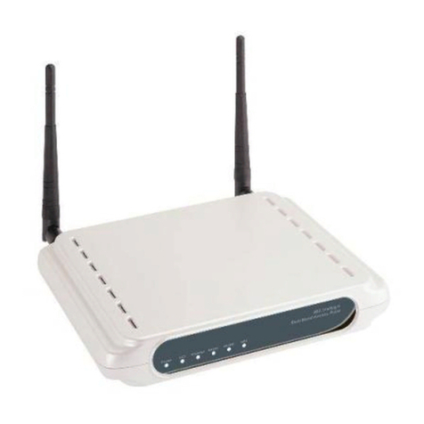
Planex GW-MF54G2 User manual

GW-MF54G2
User’s Manual

Foreword
Explanation of the signals
In order to let you set up and use this product correctly, please pay attention when reading or browsing
the manual as you see these signals listed below.
Warning/ Danger
Users should read the explanation carefully and understand it completely, otherwise users
might be in danger or even be injured.
aution/ Be areful
Remind users to be careful when setting up the product and to avoid damaging the
product or its system programs.

Federal ommunication ommission Interference
Statement
This equipment has been tested and found to comply with the limits for a lass B digital device, pursuant
to Part 15 of the F Rules. These limits are designed to provide reasonable protection against harmful
interference in a residential installation. This equipment generates, uses and can radiate radio frequency
energy and, if not installed and used in accordance with the instructions, may cause harmful interference
to radio communications. However, there is no guarantee that interference will not occur in a particular
installation. If this equipment does cause harmful interference to radio or television reception, which can
be determined by turning the equipment off and on, the user is encouraged to try to correct the
interference by one of the following measures:
- Reorient or relocate the receiving antenna.
- Increase the separation between the equipment and receiver.
- onnect the equipment into an outlet on a circuit different from that to which the receiver is
connected.
- onsult the dealer or an experienced radio/TV technician for help.
F aution: Any changes or modifications not expressly approved by the party responsible for
compliance could void the user's authority to operate this equipment.
This device complies with Part 15 of the F Rules. Operation is subject to the following two conditions:
(1) This device may not cause harmful interference, and (2) this device must accept any interference
received, including interference that may cause undesired operation.
IMPORTANT NOTE:
F Radiation Exposure Statement:
This equipment complies with F RF radiation exposure limits set forth for an uncontrolled environment.
To maintain compliance with F RF exposure compliance requirements, please avoid direct contact to the
transmitting antenna during transmitting.
This transmitter must not be co-located or operating in conjunction with any other antenna or transmitter.
Trademarks:
All trade names and trademarks are the properties of their respective companies.
opyright © 2007 All Rights Reserved.

Table of ontents
FOREWORD ....................................................................................................................................................................................................... 2
HAPTER1 INTRODU TION TO GW-MF54G2 ................................................................................................................................ 6
1. ontents of Package....................................................................................................................... 8
2. Product Function .............................................................................................................................. 9
3. GW-MF54G2 Operating Mode ..........................................................................................................11
3.1. GW-MF54G2 AP Mode Setup.................................................................................................. 12
3.2. GW-MF54G2 Router Mode Setup ........................................................................................ 13
3.3. GW-MF54G2 onverter Mode Setup ................................................................................. 14
HAPTER2 SETUP & ONFIGURATION ........................................................................................................................................... 15
1. lient’s omputer Setup....................................................................................................................... 16
2. Web onfiguration................................................................................................................................... 18
HAPTER 3 AP MODE ONFIGURATION ........................................................................................................................................ 20
AP (Access Point) .......................................................................................................................................... 21
1. AP Mode onfiguration ......................................................................................................................... 22
2. Security .................................................................................................................................................. 23
2.1. Open system or Shared Key .......................................................................................... 25
2.2. Open system with 802.1x ............................................................................................... 26
2.3. Shared Key ............................................................................................................................... 27
2.4. WPA-RADIUS .......................................................................................................................... 28
2.5. WPA-PSK ................................................................................................................................... 29
2.6. WPA2-RADIUS ....................................................................................................................... 30
2.7. WPA2-PSK ................................................................................................................................ 31
3. Wireless Advanced Settings .............................................................................................................. 32
4. Wireless Access ontrol ....................................................................................................................... 34
5. WDS Setting................................................................................................................................................. 35
HAPTER 4 ROUTER MODE ONFIGURATION ............................................................................................................................ 36
Router ................................................................................................................................................................... 37
1. Security .................................................................................................................................................. 39
1.1. Open system or Shared Key .......................................................................................... 40
1.2. Open system with 802.1x ............................................................................................... 41
1.3. Shared Key ............................................................................................................................... 42
1.4. WPA-RADIUS .......................................................................................................................... 43
1.5. WPA-PSK ................................................................................................................................... 44
1.6. WPA2-RADIUS ....................................................................................................................... 45
1.7. WPA2-PSK ................................................................................................................................ 46
2. Wireless Advanced Settings .............................................................................................................. 47
3. Wireless Access ontrol ....................................................................................................................... 49
4. WAN Port ....................................................................................................................................................... 50
4.1. Static IP ............................................................................................................................................. 50
4.2. DH P .................................................................................................................................................... 52
4.3. PPPoE .................................................................................................................................................. 54

4.4. PPTP ..................................................................................................................................................... 56
5. Virtual Server.............................................................................................................................................. 58
6. DMZ................................................................................................................................................................... 59
7. Remote Management ............................................................................................................................. 60
8. URL Filtering................................................................................................................................................ 61
9. MA Filtering............................................................................................................................................... 62
10. IP Filtering................................................................................................................................................. 63
11. DDNS ............................................................................................................................................................. 64
HAPTER 5 LIENT MODE ONFIGURATION.............................................................................................................................. 65
lient Mode ........................................................................................................................................................ 66
1. Security .................................................................................................................................................. 68
1.1. Open system or Shared Key .......................................................................................... 69
1.2. Open system with 802.1x ............................................................................................... 71
1.3. Shared Key ............................................................................................................................... 72
1.4. WPA-RADIUS .......................................................................................................................... 73
1.5. WPA-PSK ................................................................................................................................... 74
1.6. WPA2-RADIUS ....................................................................................................................... 75
1.7. WPA2-PSK ................................................................................................................................ 76
2. Wireless Advanced Settings .............................................................................................................. 77
3. Site Survey ................................................................................................................................................... 79
HAPTER 6 OTHER FUN TIONS AND ONFIGURATIONS.................................................................................................... 80
1. Status .............................................................................................................................................................. 81
1.1. System Status ................................................................................................................................ 81
1.2. Active lients .................................................................................................................................. 82
2. T P/IP ............................................................................................................................................................ 83
3. Other ................................................................................................................................................................ 84
3.1. Upgrade Firmware....................................................................................................................... 84
3.2. Reboot................................................................................................................................................. 85
3.3. Password........................................................................................................................................... 86

hapter1 Introduction to GW-MF54G2

Introduction
Thank you for purchasing GW-MF54G2, the portable and multi-function Ethernet Router. GW-MF54G2 has
1 Ethernet port, and supports both 10 and 100 Base-T connections, and you can expand your wireless
network easily.
GW-MF54G2 supports 64/128 bit WEP encryption, WPA and IEEE802.1x protocol, which can protect your
system’s security while surfing wirelessly. The IP Filtering and the MA Filtering function make it much
easier for you to filter all the users who are connecting to GW-MF54G2.
GW-MF54G2 has a lot of advanced functions, and all the configurations are easy to use. Also, GW-MF54G2
has a built-in Web server, thus you can access its settings through Web browsers, such as IE, Netscape,
Firefox, and so on. You can set up and configure the settings easily and completely and enjoy the
convenience instantly.
Special Features:
Support WPA, WPA2, WPA-PSK, WPA2-PSK, WAP-RADIUS, and WPA2-RADIUS wireless security
protocol.
Support three different function modes: AP(Access Point), Router, and onverter.
Built in Web server.
Support SSID broadcast function.

1. ontents of Package
After purchasing GW-MF54G2 Wireless Router from a distributor or an agency, please open the package
and check that all the components listed below are included. If there is any item missing or damaged,
please contact with the distributor or the agency at once.
-GW-MF54G2
-2dBi Antenna x 1
-Quick Installation Guide x 1
-Product D-ROM (User’s Manual) x 1
-A Adapter x 1
-UTP able(1 meter) x 1
-onrad manual x 1
If plug the A adapter which includes in the product package into a socket with
different voltage power supply, it will cause damage and that is not included in
warranty.

2. Product Function
Front Panel—LEDs
LEDs Status Meaning
Power ON If there is no problem with GW-
MF54G2, the Power LED will be on
after you turning on.
Wireless On/Flashing
Wireless LAN will be on if the wireless signal is fine. When
GW-
MF54G2 is receiving or transmitting data, the Wireless LAN
will be flashing.
Ethernet On/Flashing
The Ethernet LED will be on if the Ethernet port is connecting to
modem or P . T
he Ethernet LED will be flashing when receiving
or transmitting data.

Side Panel—Ports
Port Function
Ethernet Use standard LAN cable (RJ-45 connectors) to connect your P or
modem to this port.
Power Plug the power cord into this port and the other side of the adaptor
should be plugged into the socket.
Button Function Usage
Reset Reset to Default
Press and hold this button for 10 seconds, all the
configuration values of GW
-MF54G2 will reset to
default.
AP/Router/ onverter
Switching Mode
Pu
ll the switch to switch GW-
MF54G2 to AP, Router
and
onverter mode.
If you want to change the operating mode of GW-MF54G2, please do so by the steps
down below:
1. Unplug the power cord of GW-MF54G2.
2. Pull the AP/Router/ onverter switch to the mode you would like to choose.
3. Plug the power cord of GW-MF54G2 back.
GW-MF54G2 will apply to the mode you choose after power on.

3. GW-MF54G2 Operating Mode
GW-MF54G2 supports three different operating modes, which are: “AP (Access Point)”, “Router”, and
“onverter”. Please set the switch on GW-MF54G2 to the operating mode you would like to
choose base on the real situation of your network environment.
In AP (Access Point) mode, the Ethernet port of GW-MF54G2 is connected with the LAN port of your
router with a RJ-45 cable. All devices (including all the P s and laptops with wireless network card) are
connected with GW-MF54G2 wirelessly. If the AP has Internet access, all devices connected to
GW-MF54G2 can have access to the Internet as well.
In Router mode, the Ethernet port of GW-MF54G2 is connected with your cable modem or the LAN port
of your modem with a RJ-45 cable. Your computer will connect with GW-MF54G2 wirelessly and have
Internet access.
In onverter mode, the Ethernet port of GW-MF54G2 is connected with your computer’s LAN port with a
RJ-45 cable. In order to have Internet access, you have to connect with other wireless router or devices
wirelessly.
Please setup and configure GW-MF54G2 following the steps below.

3.1. GW-MF54G2 AP Mode Setup
1. Unwrap the package of GW-MF54G2 Wireless Router and check if the components are intact and
without missing anything.
2. hoose an Installation Site.
Select a suitable place on the network to install GW-MF54G2 Wireless Router. And make sure that
the Wireless Router and the DSL/ able modem are not powered on yet.
For best Wireless reception and performance, the Wireless Router should be positioned
in a central location with minimum obstructions between the GW-MF54G2 and the P s.
Also, if using multiple Access Points, adjacent Access Points should use different
hannels.
3. Set the switch on GW-MF54G2 to AP Mode.
4. onnect LAN ables.
Use standard LAN cables to connect routers or switches to Ethernet ports on GW-MF54G2. Both
10 Base-T and 100 Base-T connections can be used.
5. Power On.
Power the DSL or able modem on. onnect the adapter with GW-MF54G2 and plug the other side
of the power cord into the power socket to power on it. While detecting, the Power LED will be on,
and Ethernet LEDs will be blinking when GW-MF54G2 is transmitting files.
Plug the A Adapter which comes with GW-MF54G2 in a different voltage power
supply will cause damage on GW-MF54G2, and it is not included in warranty.

3.2. GW-MF54G2 Router Mode Setup
1. Unwrap the package of GW-MF54G2 Wireless Router and check if the components are intact and
without missing anything.
2. hoose an Installation Site.
Select a suitable place on the network to install GW-MF54G2 Wireless Router. And make sure that
the Wireless Router and the DSL/ able modem are not powered on yet.
For best Wireless reception and performance, the Wireless Router should be positioned
in a central location with minimum obstructions between the GW-MF54G2 and the P s.
Also, if using multiple Access Points, adjacent Access Points should use different
hannels.
3. Set the switch on GW-MF54G2 to Router Mode.
4. onnect LAN ables.
Use standard LAN cables to connect DSL or cable modem to Ethernet ports on GW-MF54G2. Both
10 Base-T and 100 Base-T connections can be used. Note: In order to connect GW-MF54G2
with your computer, a wireless network interface card is required.
5. Power On.
Power the DSL or able modem on. onnect the adapter with GW-MF54G2 and plug the other side
of the power cord into the power socket to power on it. While detecting, the Power LED will be on,
and Ethernet LEDs will be blinking when GW-MF54G2 is transmitting files.
Plug the A Adapter which comes with GW-MF54G2 in a different voltage power
supply will cause damage on GW-MF54G2, and it is not included in warranty.

3.3. GW-MF54G2 onverter Mode Setup
1. Unwrap the package of GW-MF54G2 Wireless Router and check if the components are intact and
without missing anything.
2. hoose an Installation Site.
Select a suitable place on the network to install GW-MF54G2 Wireless Router. And make sure that
the Wireless Router and the DSL/ able modem are not powered on yet.
For best Wireless reception and performance, the Wireless Router should be positioned
in a central location with minimum obstructions between the GW-MF54G2 and the P s.
Also, if using multiple Access Points, adjacent Access Points should use different
hannels.
3. Set the switch on GW-MF54G2 to onverter Mode.
4. onnect LAN ables.
Use standard LAN cables to connect your computer to Ethernet ports on GW-MF54G2. Both 10
Base-T and 100 Base-T connections can be used.
5. Power On.
Power the DSL or able modem on. onnect the adapter with GW-MF54G2 and plug the other side
of the power cord into the power socket to power on it. While detecting, the Power LED will be on,
and Ethernet LEDs will be blinking when GW-MF54G2 is transmitting files.
Plug the A Adapter which comes with GW-MF54G2 in a different voltage power
supply will cause damage on GW-MF54G2, and it is not included in warranty.

hapter2 Setup & onfiguration

1. lient’s omputer Setup
The computers on your LAN need to be set up to cooperate with GW-MF54G2 Wireless Router.
Please make sure that your operating system already enabled your interface card on the host and
connected to one of the LAN ports on GW-MF54G2 through at.5 cable. Be sure that LEDs on
GW-MF54G2 are already on and the LED corresponds with the port which you connected. If you switch on
GW-MF54G2 for the first time, it will automatically enable the embedded DH P server and start to
distribute IP to your host. In addition, the default IP address of GW-MF54G2 is “192.168.1.100”. If your
operating system is Windows 98/2000/XP, you may be able to use command of “ipconfig” to inquire
whether you have the correct IP address or not. If you are using Linux/Unix-Like system, you can use
“ifconfig” to check your NI (Network Interface ard) address. The instructions are as follows:
Windows98
1. lick “Start→Programs→MS-DOS” or “Start→Run…” and type in “command.exe” and then
press enter.
2. “MS-DOS” window will appear.
3. Type “ipconfig” after the command of “c:>” and then press enter.
4. MS-DOS will appear your NI address in the window, please take notice of the value of “IP
Address” and “Default Gateway.”
5. The value of “Default Gateway” is the IP address of GW-MF54G2.
Windows2000/XP
1. Please make sure that you do have the authority to access as an “Administrator” or you are
already one of the “System Administrators.”
2. lick “Start→Programs→Accessories→ommand Prompt” or “Start→Run…,” and then
type in “cmd.exe” and press enter.
3. It will appear a “MS-DOS” window.
4. Type “ipconfig” after the command of “c:>” and then press enter.
5. MS-DOS will appear your NI address in the window, please take notice of the value of “IP
Address” and “Default Gateway.”
6. The value of “Default Gateway” is the IP address of GW-MF54G2.
Linux / Unix-Like
1. At first please make sure that your NI are already enabled and works properly.
2. And be sure you have “root
” number or your already are one of the members of a “root” group.
3. Please type “ifconfig” of “ifconfig -a” after “#” and then press enter.
4. It will appear your present NI address in the window, please take notice of the value of “IP
Address” and “Gateway.”
5. The value of “Gateway” is the IP address of GW-MF54G2.
If you can get “IP Address” and “Gateway,” normally, it means that you may use web browser to
configure GW-MF54G2. Type your destination—“
http://192.168.1.100
” (default IP Address of
GW-MF54G2) on the Address Bar in the web browser. If you have changed the default IP Address of
GW-MF54G2, please type in the new address on the address bar.

Note: If you set your GW-MF54G2 to AP or Router mode, you will have to connect with GW-MF54G2
wirelessly. Please connect to a wireless AP with the name of “ onrad” so you can log on to the
configuration webpage.

2. Web onfiguration
GW-MF54G2 contains an HTTP server. This enables you to connect the router, and configure it by using
your web browser.
The GW-MF54G2 Wireless Router's default IP Address is “192.168.1.100”. If the IP address has already
used by another device, the other device must be turned OFF until GW-MF54G2 is allocated a new IP
Address.
Using Web Browser
To establish a connection between your P and the GW-MF54G2 Wireless Router:
1. Start the WEB browser.
2. In the Address box, enter “http://192.168.1.100” which is the default IP Address of the
GW-MF54G2 Wireless Router. Press “Enter” on your keyboard, and the pop-up will ask you to enter
the User Name and Password to get into the program.
3. Enter the default User Name “admin” and Password “0000” and then click “OK” to enter the
system. You can also put a check in the “Remember my password” check box, and next time you
do not need to enter password to enter the system.
4. After entering the system, GW-MF54G2 will show you the homepage. During configuration, you can
use the links on the top of the page to navigate. Besides, it is necessary that, after configuring, you
should click “Apply” to enable the settings you’ve made.


hapter 3 AP Mode onfiguration
Other manuals for GW-MF54G2
1
Table of contents
Other Planex Network Router manuals

Planex
Planex BLW-04G User manual

Planex
Planex FX-16IM User manual

Planex
Planex FX-16NW User manual

Planex
Planex BLW-04GZ-PK User manual

Planex
Planex BLW-54SAG User manual

Planex
Planex BLW-54SG User manual

Planex
Planex BLW-54SAG User manual

Planex
Planex BRL-04AX User manual

Planex
Planex BLW-04EX User manual

Planex
Planex MZK-W04N User manual

Planex
Planex CQW-MR200 User manual

Planex
Planex BRM-04 User manual

Planex
Planex BRL-04EX User manual

Planex
Planex FMG-24K User manual

Planex
Planex BRL-04FXP User manual

Planex
Planex eXgate Series User manual

Planex
Planex BRL-04FM User manual

Planex
Planex FMS-24K User manual

Planex
Planex MZK-WDPR User manual

Planex
Planex BLW-54CW3 User manual