Platinum Tools Snap Shot User manual

User Manual
Snap Shot
TM
Fault Finding/Cable Length Measurement SSTDR
Accurately nds cable length,
impediments in the cable and
conditions at the end of every
wire in your data, power, or
communications/video system
up to 3,000 ft.
Memory
Holds up to two different NVP values for
multiple cable tests.
Calibration
Ability to calculate NVP for
any known cable length.
Test
Tests length, opens or shorts present on
the cable, up to 3,000 ft.
Tone Generation
Produces four different tones for locating
cables.
99 Washington Street
Melrose, MA 02176
Phone 781-665-1400
Toll Free 1-800-517-8431
Visit us at www.TestEquipmentDepot.com

2
User Manual
Table of Contents
About this Manual...................................................................3
Symbols and Icons..............................................................3
Terms and Descriptions......................................................4
Safety Information..............................................................5
Equipment and Accessories.....................................................6
Design Features.......................................................................7
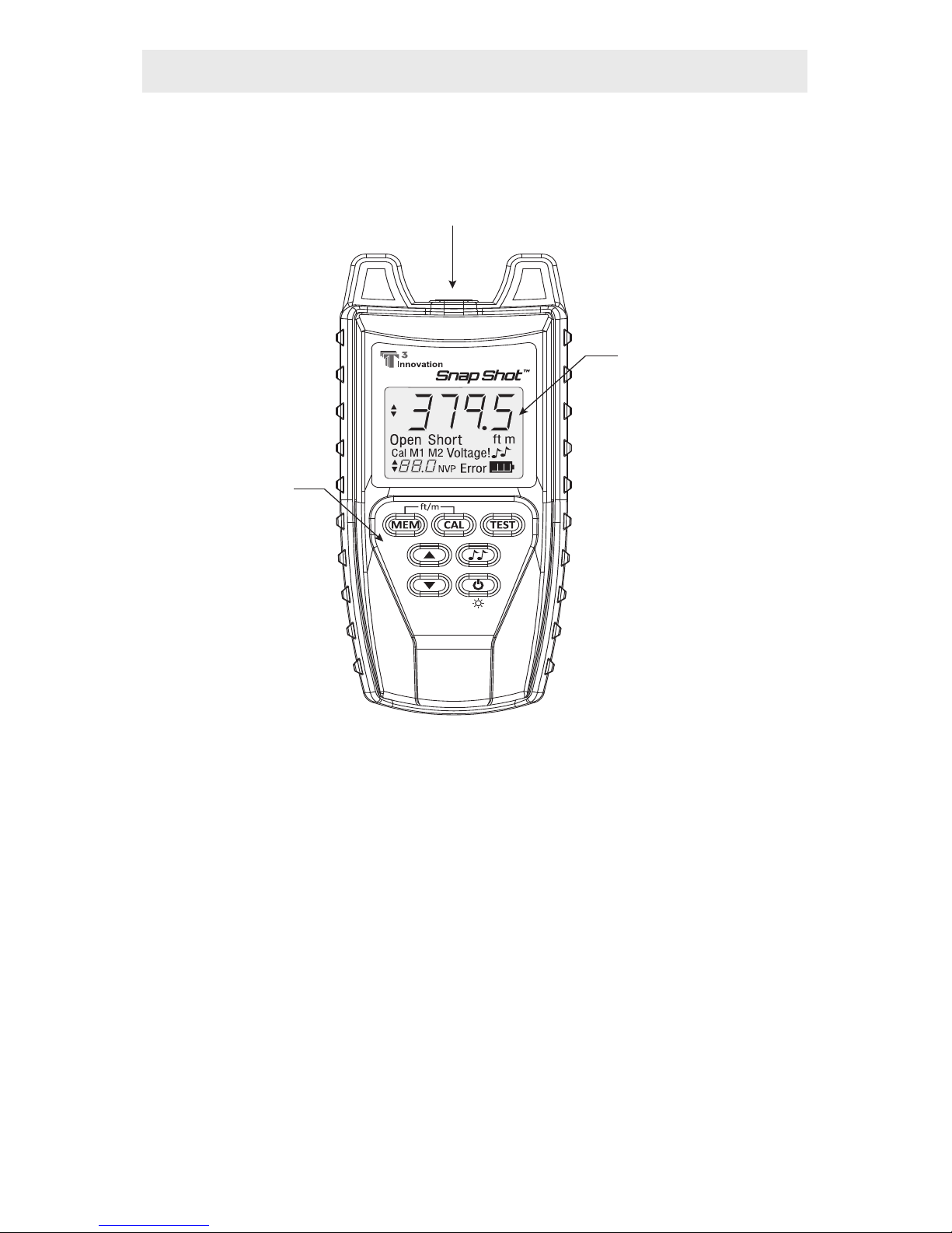
Snap Shot™ Description.........................................................8
F-Connector................................................................8
LCD Display Screen.............................................................9
Keypad.................................................................13
Operations.....................................................................15
Turning the Unit On/Off...................................................15
Automatic Power Down...................................................15
Cable Testing General Guidelines....................................16
Using Memory Storage.....................................................16
Recalling Stored NVP Values.................................17
Adjusting NVP Values................................................18
Using Calibration Mode....................................................19
Using Test Mode...............................................................22
Using Loop Testing............................................................24
Using Tone Mode..............................................................25
Maintenance.................................................................26
Battery Replacement........................................................26
Cleaning.......................................................................26
Storage....................................................................26
Customer Service...................................................................27
ContactingPlatinumTools..................................................27
Additional Accessories.....................................................27
Warranty Information.......................................................28
Product Registration.........................................................28
Disposal......................................................................28
Returns........................................................................28
Specications....................................................................29
Appendix A............................................................................30
Snap Shot
TM
Fault Finding/Cable Length Measurement TDR

3
ABOUT THIS MANUAL
The Snap Shot™ is a self contained, hand-held, battery powered test unit
operated by contractors, repair technicians, and other authorized users.
This device is used to accurately test voice, data, and video cables. The
Snap Shot™ determines cable length, identies cable faults, and quickly
discovers the Nominal Velocity of Propagation (NVP) for a cable using
Spread Spectrum Time Domain Reectometry (SSTDR).
Symbols & Icons
The following symbols are used throughout the manual or in the display
screen of the Snap Shot™ to help you avoid personal injury and potential
damage to the test equipment (Table 1).
3
Symbol Denition
Warning: Potential for personal injury
Caution: Potential for damage or destruction to equipment.
Voltage! Voltage detection symbol. Appears when the voltage on the
cable is unsafe and exceeds 60 volts peak AC or DC.
Conformité Européenne. Conforms with European Economic
Area directives.
Disposal information.
!
Table 1. Symbols and Icons

4
Terms Description and Uses
Nominal Velocity of
Propagation (NVP)
Also known as the Velocity of Propagation (VOP),
NVP is the speed of an electrical signal traveling
through a cable, measured as a percentage of the
speed of light.
Safety Extra Low
Voltage (SELV) ▪A rating determined by the International Electro-
technical Commission that denes safe voltage
standards when using electronic devices.
▪SELV is 60 volts DC or Peak AC (45 volts RMS).
F-Connector ▪Connector for a coaxial cable.
Spread Spectrum
Time Domain
Reectometry
(SSTDR)
▪Spread spectrum is the technological foundation of
cell phone communications and is used to transmit
a small, but nevertheless recognizable, signal in a
high noise environment.
▪By combining spread spectrum with TDR technol-
ogy, SSTDR allows for a length test on cables
without interference from voltage.
Terms and Descriptions
Table 2 denes the terms used throughout the document and provides
information to assist you with proper operation and understanding of the
unit and its functions.
Table 2. Terms and Descriptions

5
Safety Information
To ensure safe operation of the Snap Shot™, follow the instructions
carefully and observe the warning and caution messages listed in Table
3. Failure to observe warnings can result in severe injury or death and can
damage the unit.
Table 3. Safety Information
Notication Denition
The Snap Shot™ is designed for use on cabling systems
with or without voltage.
▪The Voltage! Icon turns on when the voltage exceeds
Safety Extra Low Voltage (SELV) rating of 60 volts peak
AC or DC.
▪Internal components are protected up to 400 volts peak
AC or DC.
▪Operating the Snap Shot™ when a voltage source exceeds
60 volts peak AC or DC may pose a safety hazard for the
user.
Do not place equipment and its accessories in the trash.
Items must be properly disposed of in accordance with local
regulations.
It is not recommended to use the Snap Shot™ when the
Voltage! Icon is present.

6
The following list of equipment and accessories are used with the Snap
Shot™ in order to properly test cables. The items illustrated and described
in Table 4 are provided with your purchase of the Snap Shot™. Refer to
the Additional Accessories section for a listing of additional products
that can help make testing easier.
Table 4. Snap Shot™ Equipment and Accessories
EQUIPMENT AND ACCESSORIES
Accessory Product
Number Description
TAD001 F-connector Coupler, High
Performance F81
18303 Adapter, F-Jack to BNC Jack
TCA001 Cable Assembly, Insulated Push-
On F to RJ45 Plug
TCA002 Cable Assembly, Insulated BNC to
Alligator Clips
TCA003 Cable Assembly, Insulated Push-
On F-Connector to Alligator Clips

7
DESIGN FEATURES
▪1% length accuracy
▪Ability to measure cables with voltage
▪Stores up to two NVP values
▪Displays length reading in feet or meters
▪Easy to Operate
▪Extra large seven-segment, back lit LCD screen with icons that clearly
display test results
▪Tests any copper cable including data, voice, video, lamp wire, and
romex cables
▪Discovers NVP value for cables with known length
▪Automatic pre-test voltage checks
▪Identies cable faults
▪Tone generator with selectable tone cadence to easily trace cables
▪Conserves power and supports long battery life with Auto-off feature
and battery life indicator

8
Snap Shot™ Description
Figure 1. Snap Shot™
F-Connector
One F-Connector is located at the top of the Snap Shot™. The connector
enables you to test and measure single cables.
Note: Additional accessories are provided with your purchase of the
Snap Shot™ for use with twisted pair, coaxial, and two-wire
cables. Refer to the Cable Testing General Guidelines
section of the manual for more details.
The Snap Shot™, illustrated in Figure 1, has 3 main parts: the F-Connector,
LCD display screen, and the keypad.
LCD Display Screen
F-Connector
Keypad

9
Adjustment Indicator
Cable Faults
Calibration Mode
Battery Life Indicator
Cable Length
Unit of Measurement
Tone Mode
Error Message
NVP Value
Memory Storage Locations Voltage Detected Warning
Figure 2. LCD Display Screen
LCD Display Screen
The Snap Shot™ has a high contrast LCD display screen, shown in Figure
2 below. The LCD display screen shows the following: modes and related
icons, cable length, memory storage and related icons, NVP value, cable faults,
error message, voltage detection warning, and battery life indicator.
Test Mode
When the TEST button is pressed, the measured cable length (in units of
feet or meters) appears at the top of the LCD display screen. The following
values and icons display in the screen when a single test is run:
▪Storage Location – The selected storage location (M1 or M2) appears
in the lower left corner of the display screen above the NVP value.
▪NVP Value – The value saved in the selected storage location
appears in the lower left corner of the screen. This value is used to
calculate the displayed cable length.

10
Memory Storage
When the MEM button is selected, a series of values and icons appear in
the LCD display screen. See Table 5 for a description of the display screen
updates when Memory Storage is in use.
Table 5. Memory Storage Icons and Values
Icons and Values Description
Memory Storage
Locations The unit has two memory storage locations: M1 and
M2. The selected storage location appears above
the NVP value in the lower left corner of the LCD
display screen.
NVP Value The NVP value for the selected storage location
appears next to the “NVP” icon in the lower left
corner of the LCD display screen.
Adjustment Indicator The adjustment indicator icon demonstrates that the
NVP value can be adjusted.
▪The icon, displayed as two Up/Down arrows,
appears to the left of the NVP value.
Cable Length The cable length, displayed in feet or meters, ap-
pears in the upper right corner of the display screen.
When a cable is not attached to the Snap Shot™ the
length will read “0”.
Note: Refer to the Using Memory Storage section to learn how to
store multiple NVP values for testing purposes.
Tone Mode
When the TONE button is selected, two musical notes blink in the lower
right corner of the LCD display screen to demonstrate the unit is set to
tone tracing. The following icons appear in the display screen when Tone
Mode is in use:
▪Cadence – There are four cadence options: HI, LO, HL1, and HL2. The
last selected cadence appears in the top row of the display screen.
▪Adjustment Indicator – Two arrows appear to the left of the
selected cadence to indicate that cadence can be adjusted.
Note: A tone probe is used for the tone tracing functionality of the
Snap Shot™. This item is sold separately. Refer to the Additional
Accessories Section for a listing of available products.

11
Calibration Mode
When the CAL button is pressed, the “Cal” icon appears in the lower left
corner of the display screen. The icons and values described in Table 6
appear in the LCD display screen when the unit is set to Calibration Mode.
Table 6. Calibration Mode Icons and Values
Icons and Values Description
Cable Length The last entered cable length appears (in units of
feet or meters) in the top row of the LCD
display screen.
Adjustment
Indicator The adjustment indicator icon, denoted by two
Up/Down arrows, indicates that cable length can
be adjusted while in Calibration Mode.
▪The icon displays to the left of the last inputted
cable length.
NVP Icon The “NVP” icon appears in the bottom row of the
LCD display screen.
▪Three dash lines “- - -” appear to the left of
the “NVP” icon demonstrating that the NVP
has not been calculated for the entered cable
length.
Note: Refer to the Using Calibration Mode section to learn how to
calculate the NVP of a cable.

12
Cable Faults
The device checks for two cable faults during testing: Open and Short. The
cable faults, explained in Table 7 below, appear in the middle of the LCD
display screen.
Battery Life Indicator ( )
The battery life icon appears in the lower right corner of the LCD display
screen to demonstrate the approximate remaining battery life. A new
battery shows three bars. The number of bars decreases as the battery
is nearing depletion. The icon begins to ash at 4 volts when the battery
needs to be replaced. Results may be unreliable at this point.
Note:The Snap Shot™ will turn off if the power supply goes out of
regulation from a low battery condition.
Voltage Detected Warning (Voltage!)
The “Voltage!” icon appears in the lower right corner of the display
screen when the voltage detected on a cable exceeds SELV rating of
60 volts peak AC or DC. If the icon appears, the Snap Shot™ should be
disconnected immediately from the source of the voltage.
Note: The Snap Shot™ continually checks for the presence of voltage
on a connected cable.
Table 7. Cable Faults
Cable Faults Description
Open An “Open” error indicates a wire connection within
the cable is not continuous throughout the length
of the cable.
Short The “Short” icon appears when the two wires
within a cable are electrically connected. This is
also known as a short circuit.

13
Power/Backlight
Tone
Test
Calibration
Toggle Units
Memory
Up/Down
Error
The “Error” message appears in the lower right corner of the LCD display
screen under the following circumstances:
▪Calibration results in an invalid NVP value outside of the 20 to 99.9
NVP value range.
▪SSTDR reection was not detected due to a properly terminated cable
or excess signal loss.
Note: Refer to the Using Calibration Mode and Using Test Mode
sections for trouble-shooting the “Error” message when using
either of these modes.
Keypad
The Snap Shot™ is equipped with seven buttons, illustrated in Figure 3.
Four buttons, appearing in the top two rows of the keypad, are used with
Test and Tone Modes. Two Up/Down buttons are used to edit. One button
is used to power the unit On/Off. The button functions are explained in
Table 8.
Figure 3. Keypad

14
Table 8. Keypad
Button Function
Memory The Memory button is used to store up to two NVP values for
testing purposes.
▪Short presses of the Memory button toggles between the two
memory storage locations: M1 and M2.
▪A long press (two seconds) of the button stores an NVP value in
the selected storage location.
▪A long press (two seconds) of the Memory and Calibration
buttons simultaneously toggles between units of measurement
(feet and meters).
Calibration The Calibration button allows you to discover the NVP value
based on an entered cable length.
▪Short presses of the Calibration button adjust cable length in
increments of 50 ft or 20 m within the range of 50 ft to 1,000 ft
or 20 m to 300 m.
▪A long press (two seconds) of the Calibration button aborts
Calibration mode and enters Test Mode.
▪A long press (two seconds) of the Memory and Calibration
buttons simultaneously toggles between units of measurement
(feet and meters).
Test The Test button initiates length testing on the connected cable.
▪A short press runs a single test on demand.
▪A long press (two seconds) of the button starts continuous test-
ing. Pressing any button (except Power) stops loop testing (or
the unit turns off after 3 minutes).
Tone The Tone button allows you to trace cables by sound.
▪A short press of the button transmits an audio tone from the unit
through the connected cable.
▪Subsequent presses of the Tone button toggles between Test
and Tone Modes.
Up/Down ▪In Tone Mode, the Up/Down buttons allow you to select a
cadence (HI, LO, HL1, and HL2).
▪In Calibration Mode, the buttons are used to adjust the
measured cable length within the following length ranges: 10
m – 300 m or 25 ft to 1,000 ft.
▪In Memory Storage and Test Mode, the Up/Down buttons
enable you to adjust the NVP value for the selected memory
storage location (M1 or M2).
Power ▪A short press of the Power button turns the Snap Shot™ On.
▪Subsequent presses of the button toggle the backlight On
and Off.
▪A long press (two seconds) of the Power button turns the unit off.

15
Turning the Unit On/Off
Turn Unit On
▪Press the POWER button to turn the unit ON.
▪The Snap Shot™ immediately runs a length test when powered ON.
Turn Unit Off
▪Press and hold down the POWER button for two seconds to turn the
unit OFF. The display screen goes blank.
Automatic Power Down
The Snap Shot™ automatically turns off after a period of inactivity to
conserve battery power. The automatic power down feature is dependent
on which mode is in use and if voltage is detected on the cable being
tested (see Table 9).
Table 9. Automatic Power Down.
Operations
To ensure safe operation of the Snap Shot™, follow the instructions
carefully and pay attention to the warning and caution symbols. Failure
to observe warnings can result in severe injury or death and can damage
the unit.
Mode Time
Test Mode 1 minute
Loop Testing 3 minutes
Tone Mode 15 minutes
Calibration Mode 1 minute

16
Cable Testing General Guidelines
The Snap Shot™ determines the length of a variety of cable types, calculates
the NVP value of a cable with a known length, and identies cables by sound.
Important Points to Note
The Accessories provided with the Snap Shot™ must be used to properly
connect cables.
▪For coaxial cables, afx the F-Connector Coupler to the F-Connector
on the top of the unit. Then connect the end of the cable to be tested
to the other side of the F-Connector Coupler.
▪When testing a cable with an RJ45 jack, connect the F-Connector
Coupler to the F-Connector on the top of the unit. Then attach the
Insulated Push-On F to RJ45 Plug.
▪To run tests using the Alligator Clips, rst afx the F-Connector Coupler
(or F-Jack to BNC Jack) to the top of unit. Then attach the proper Cable
Assembly to Alligator Clip accessory.
Important Safety Points
The Voltage! Icon appears when the voltage surpasses SELV
rating of 60 volts peak AC or DC. It is not recommended to
operate the Snap Shot™ on cable systems exceeding a voltage
value of 60 volts.
If the Voltage! icon appears, the Snap Shot™ should be
disconnected immediately from the source of the voltage.
Internal components of the Snap Shot™ are protected to 400
volts peak AC or DC. Connecting the unit to cabling systems
with voltage above 400 volts peak AC or DC may damage the
test unit and pose a safety hazard for the user.
Using Memory Storage
The Snap Shot™ features two memory storage locations (M1 and M2)
allowing you to save two NVP values for cable testing.
Note: For the rst use of the Memory Storage feature, the default NVP
values for both M1 and M2 storage locations is 84.6 NVP. This is a
common value for testing RG6 coaxial cables.

17
Note: Single presses of the MEM button toggles between the two
memory storage locations.
Cable length does not update automatically when toggling
between the two memory storage locations. To achieve an
accurate length measurement when selecting a different stored
NVP value, a test must be run. Refer to the Using Test Mode
section for instructions on measuring cable length.
Figure 4. LCD Display Screen in Memory Storage
Recalling Stored NVP Values
1. Connect one end of the cable to the Snap Shot™. Use connection
accessories according to the type of cable you are testing.
2. Press the POWER button to turn the unit ON.
3. Press the MEM button to recall the stored NVP Value. The LCD
display screen, illustrated in Figure 4 below, shows the following:
▪The current storage location (M1 or M2) and the NVP value last
saved in the selected location.
▪The adjustment indicator icon appears in the screen indicating
NVP is editable.
▪The cable length calculated during the last test.

18
Adjusting NVP Values
1. Power the unit ON.
2. Select the memory storage location you would like to adjust (M1 or
M2) through short presses of the MEM button.
3. Press the UP and DOWN buttons to increment or decrement the NVP
value. Press and hold the UP or DOWN buttons to quickly increase or
decrease the NVP value.
Note: If the NVP value is unknown, you can determine the NVP value
for the cable you are testing in the following ways:
▪View the listing of common NVPs by cable type on the back-
side of the Snap Shot™.
▪Refer to Appendix A for an extended listing of NVP values.
▪Use Calibration Mode to set the NVP value if the length of
the cable is known. Refer to the Using Calibration Mode
section for instructions on calculating NVP.
4. Press and hold down the MEM button for two seconds to save the
adjusted NVP value. The adjusted NVP value will be stored in the unit’s
memory for the specied storage location.
Note: A short press of the MEM button or selection of any other
buttons during editing will discard the adjusted value.
If the unit is turned OFF prior to saving the edited NVP value,
the Snap Shot™ will recall the adjusted NVP value. However,
the adjusted value will not be saved in either of the two
storage locations.

19
Using Calibration Mode
Use Calibration Mode to calculate the NVP value for a known cable length
between 25 ft - 1,000 ft or between 10 m - 300 m. The determined NVP
value can be stored in the unit’s memory allowing you to easily test cables
without recalibrating the NVP every test.
Note: Calibration Mode is used with unterminated cables only
For the rst use of Calibration Mode, the unit defaults to a
cable length of 50 ft, when the unit is set to feet, or 20 m when
the Snap Shot™ is set to meters.
When Calibration Mode is in use, the connected cable is tested
for the presence of voltage. If detected, a dynamic voltage
warning displays until the unit is disconnected from the voltage
source.
1. Connect a cable to the Snap Shot™. Use connection accessories
according to the type of cable you are testing.
Note: The Snap Shot™ cannot be calibrated without a cable attached
to the unit.
2. Press the POWER button to turn the unit ON.
3. Press the CAL button. The LCD display screen, illustrated in Figure 5
below, shows the following upon entering Calibration Mode:
▪The last entered cable length, in units of feet or meters.
▪The adjustment indicator icon appears in the screen indicating
the cable length is editable.
▪The “Cal” icon appears in the lower left corner.
▪Three dashes “- - -” are displayed to demonstrate that the NVP
value has yet to be calculated.
Figure 5. LCD Display Screen in Calibration Mode

20
Cable Faults Description
Up/Down The Up/Down buttons allow you to adjust the cable length
within the range of 10 m – 300 m or 25 ft to 1000 ft.
▪Press the UP and DOWN buttons to increment or
decrement the length.
▪Press and hold the UP or DOWN button to quickly
increase or decrease the cable length.
Calibration Press the CAL button to increase cable length in 50 ft or
20 m increments according to the unit of measurement
selected (feet or meters).
Table 10. Adjusting Cable Length.
4. Verify the Snap Shot™ is set to your desired unit of measurement (feet
or meters). To change the unit of measurement, press and hold down
the MEM and CAL buttons simultaneously for two seconds. The unit of
measurement will adjust in the LCD display screen.
5. Enter the length of the attached cable. See Table 10 for a description of
how to adjust cable length using the Up/Down and Calibration buttons.
Note: Once the maximum length (1,000 ft or 300 m) is reached
through use of the CAL button, a subsequent press of the
button adjusts the cable length to the default cable length (50
ft or 20 m).
To abort Calibration Mode and retain your previous inputted
cable length, press and hold down the CAL button. The unit
defaults to Test Mode.
6. Press the TEST mode button. The following updates occur in the LCD
display screen (see Figure 6):
▪The three dashes in the lower left corner disappear. The calcu-
lated NVP value for the inputted cable length appears in place
of the three dashes.
▪The cable length displays in the upper right corner.
▪The Memory Storage location last selected (M1 or M2) appears
above the NVP value.
▪The adjustment indicator icon appears in the lower left corner.
▪The “Open” icon displays as Calibration Mode is used with
unterminated cables only.
Table of contents
Other Platinum Tools Measuring Instrument manuals

Platinum Tools
Platinum Tools Net Prowler TNP700 User manual

Platinum Tools
Platinum Tools LANSeeker TP500 User manual

Platinum Tools
Platinum Tools TDG310 User manual

Platinum Tools
Platinum Tools LANSeeker TP500 User manual

Platinum Tools
Platinum Tools Cable Prowler TCB300 User manual

Platinum Tools
Platinum Tools LANSeeker TP500 User manual
Popular Measuring Instrument manuals by other brands

Mi-Sol
Mi-Sol WS4000 instruction manual

Tek-Trol
Tek-Trol TEK-DP1620A instruction manual

protech
protech TD2082 user manual

B+K precision
B+K precision 830C instruction manual

KEPCO
KEPCO 520 Series manual

Kyoritsu Electrical Instruments Works, Ltd.
Kyoritsu Electrical Instruments Works, Ltd. KEW8146 instruction manual