12 13
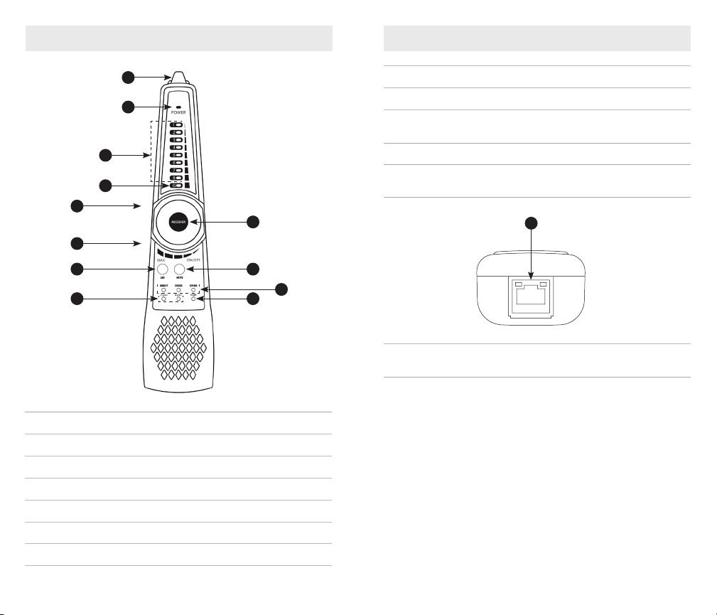
5. Connector Wiring and Short Circuit Detection
Press the “MUTE” button on the probe: when the indicator light of
the port is lit, the 1-8 and G indicator lights show that the connection
between the cable wires and the connector is continuous. For a single-
ended shorts test, insert one end of the network cable into the RJ45 port
of the probe, then press “MUTE”. If the “Port” LED is lit, there is a short
circuit in the network cable.
6. 2-Pair/4-Pair Indicator
Connect the ends of the network cable to Switch and to the RJ45 port of
the tone generator, then press the “SET” key to switch to the “SWITCH”
mode. If the 1, 2, 3 and 6 indicators LEDs are lit, only 2 pairs in the cable
or port are continuous. If all indicators 1-8 are lit, all 4 pairs of the cable or
port are continuous.
7. A Break in the Wire
A tone that is not detected at the end of the cable may indicate a
break in the wire(s). Trace the cable until the signal is not heard. This
would indicate where the break is located. You may need to cut off the
connector to trace the wires in a twisted pair cable individually with the
alligator clip accessory.
8. Use with PoE switches
The RJ45 ports of tone generator and probe can withstand a maximum of
60VDC, the wire can be traced directly in connection with PoE switch.
Wire Map Detection
Cable Conguration Detection
Step 1: Insert the ends of the network cable into the RJ45 port of the tone
generator and the RJ45 jack of the probe. Turn on the probe.
Step 2: Switch the tone generator to UTP mode. The 1-8 and G indicators
will show the type of cable and the 2-pair or 4-pair indicators show the
cable or port is continuous on wires 1, 2, 3 and 6 or wires 1-8.
Quickly determine the cable conguration through the tone generator or
tone probe. If the Direct or Cross indicator is lit, the cable conguration
is wired correctly according to TIA568A/B standards. Once the indicators
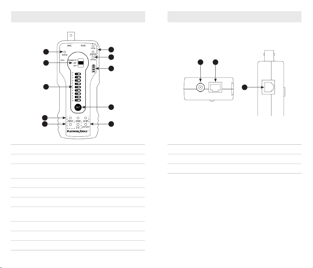
OPERATING INSTRUCTIONS
Network Cable Port Continuity Detection
In the UTP mode, press the “SET” key to switch to “LOCAL” mode.
Local Port (Near-End) Continuity Detection
When the “LOCAL” indicator
LED is on, connect the other
end of the network cable to
the tone probe “UTP” port or
disconnect the UTP port. The
1-8 and G lights indicate the
near-end continuity status
of network cable or ports
within 1 meter of the tone
generator.
In the picture shown, the 1st
wire of the network cable port
on the side of tone generator
is disconnected.
OPERATING INSTRUCTIONS
ash, the tone probe will beep to indicate the cable conguration. A
single beep indicates a standard TIA568A/B congured cable, a double
beep indicates a cross cable and a triple beep is a different or wrong
conguration.