FL150-3 User Manual
Page 05
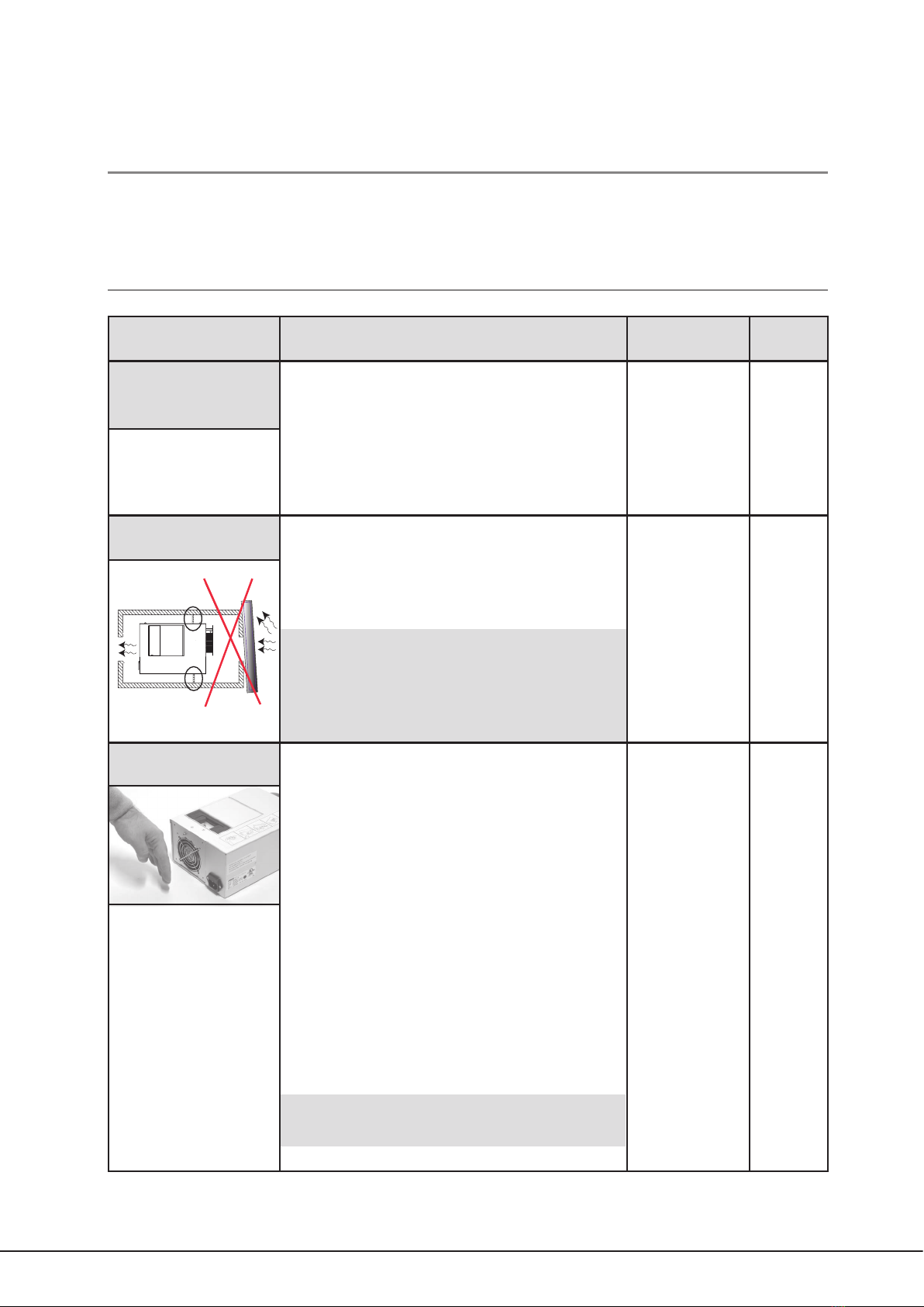
2.2 Mounting in closed compartments
The FL 150 - 3 is suitable for mounting in closed compartments such as cabinets or showcases.
When installing in closed compartments two very important criteria must be fullled.
1. When installing one or more light generators in a closed compartment
the volume of the chamber cannot be less than 0,35m3per light generator.
Furthermore, the back of the light generator cannot be placed closer than 15
cm to any of the walls of the compartment
The temperature of the surrounding area inside the compartment cannot
exceed 40°C.
2. In compartments smaller than 0,35 m³ the light generator needs to »breathe« to keep cool.
Ventilation holes must be made in the compartment corresponding to min. 50 cm² of air intake and min. 50
cm² of exhaust air. When using this installation method, the air intake and exhaust of the light generator
must be separated. Also the holes of the cabinet must be pointed in different directions. When doing so, it is
possible to install the light generator in very small compartments.
Also here, the temperature of the surrounding area cannot exceed 40 °C.
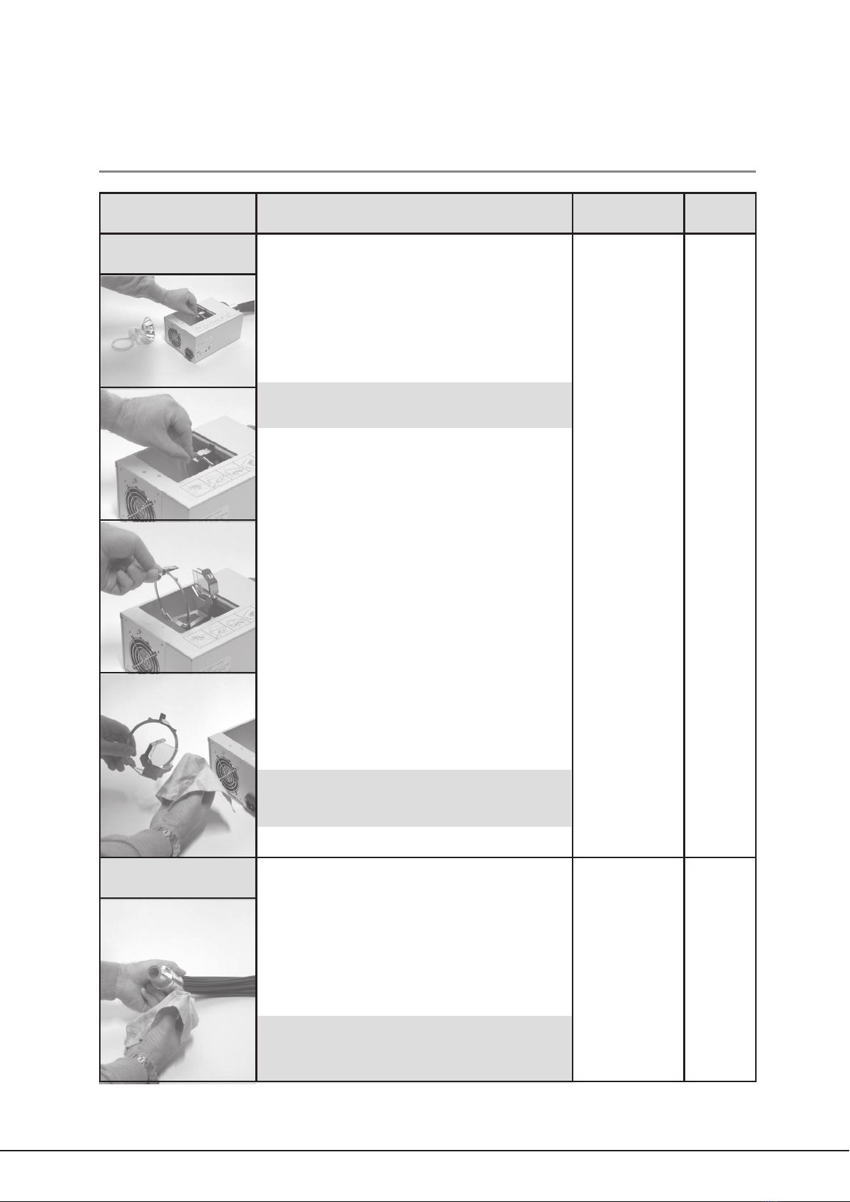
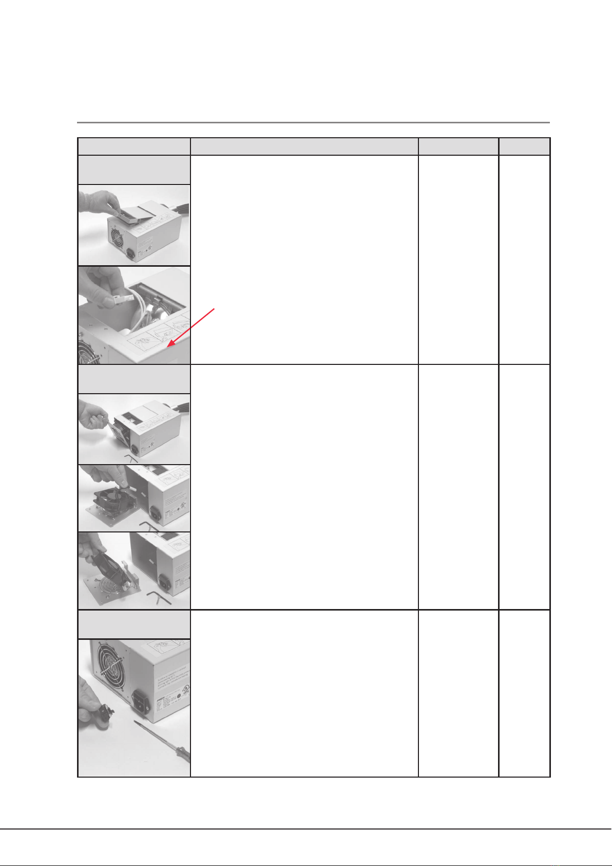
Some examples of seperation of air intake and air outlet holes are given below.
Example 1.
In this example, the air intake and the exhaust is separated by a space
dividing plate. This plate can be placed anywhere along the sides of the light
generator as long as it ts exactly to the light generator.
Example 2.
In this second example, a hose-like tting is made. In order to ensure an
airtight separation of the airow. This method is the most exible, as the air
separator can be formed to suit the needs of exactly your application. Use e.g.
ventilation ange +7800 0505 for standard Ø100 mm exible ventilation hose.
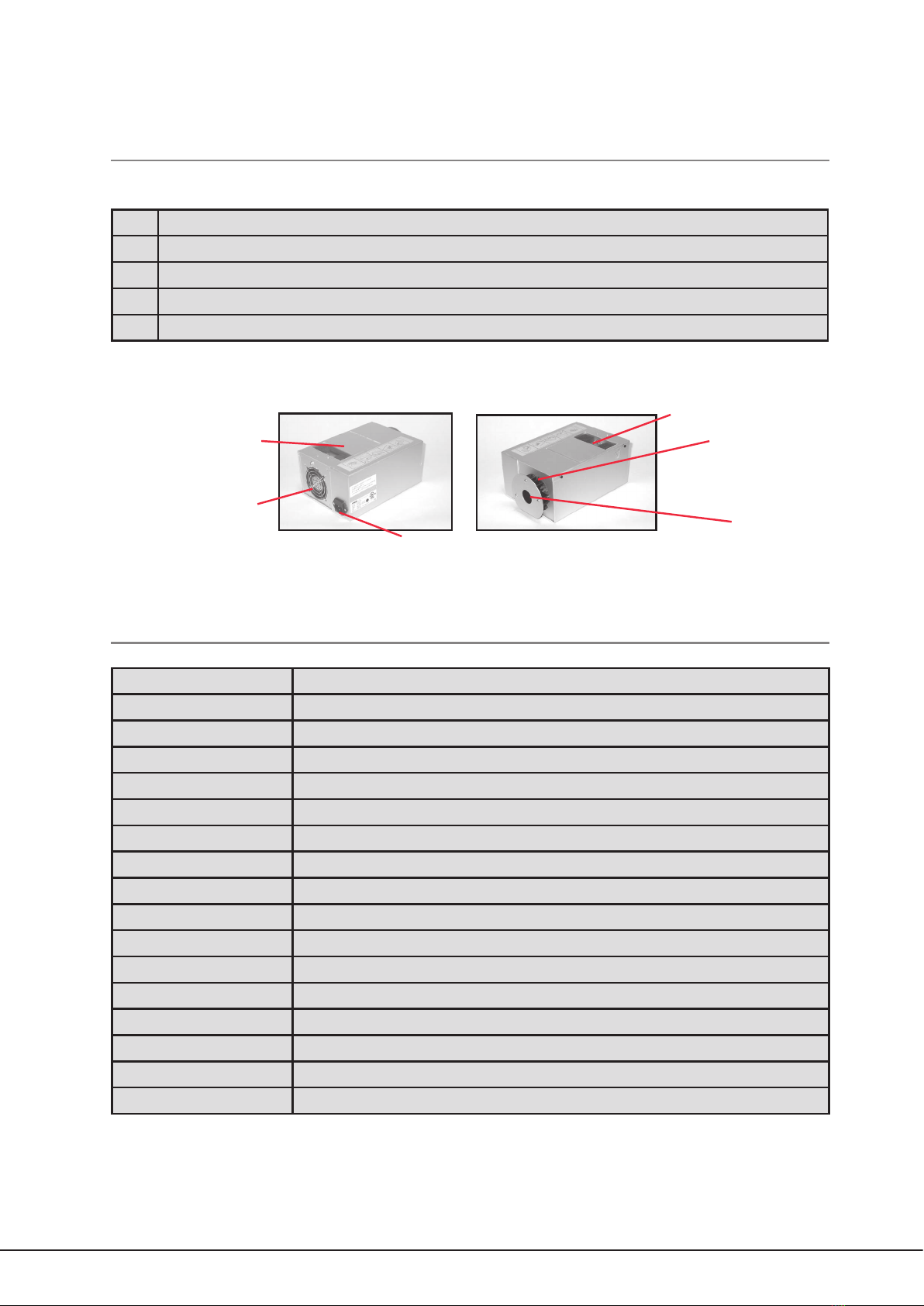
1.
Min.
15 cm
Volume: Min. 0.35 m3
Temperature: Max. 40oC
Note.
If the mounting and ventilation instructuion are not observed, the light generator will become
too hot, causing the thermal protection to activate and the light generator to switch off.
Min.
15 cm
Volume: Min. 0.35 m3
Temperature: Max. 40oC
Min.
15 cm
Volume: Min. 0.35 m3
Temperature: Max. 40oC