PLENY Folding Exercise Bike Owner's manual

Important – Please read these instructions fully before assembly or using
These instructions contain important information which will help you get the best from your
equipment and ensure safe and correct assembly, use and maintenance.
Folding Exercise Bike
Assembly &
User Instructions - Please
keep
for future reference
TM
If you need help or have damaged or missing parts, contact Customer Service:

1
Contents
Safety Information
Components - Parts
Components - Fixings
Assembly Instructions
Computer Operation
Exercising Information
Before starting
Muscle chart
Warming up and cooling down
Care and Maintenance
Exploded Parts Diagram
Parts List
2
3
4
5-6
9
Adjustment / Folding away 7
31-01
Installation of Batteries / Workout area 8
10
11
12-13
14
15
16
TM

3
Components - Parts
Please check you have all the parts listed below
Note: Some of the smaller components may be pre-fitted to larger components. Please check carefully
before contacting PLENY regarding any missing components.
21. Main frame x 1
6. Holder of Monitor x 1
50-1. Front Stabiliser x 1 50-2. Rear Stabiliser x 115. Saddle Stem Instert x 1
39.Pedal (R) x 174. Pedal (L) x 110. Saddle x 1
1. Handle Bar x 1 5. Exercise Monitor x 1
TM

4
Please check you have all the fixings listed below
Note: Some of the fixings are pre-fitted to the larger components.Please check carefully before contacting
Pleny regarding any missing fixings.
Ruler - Use this ruler to help correctly identify the hardware
0 5 10 15 20 25 30 35 40 45 50 55 60 65 70 75 80 85 90 95 100 110 115 120 125 130 135 140 145 150 155 160 165 170
105
Components - Fixings
51
M8 x50mm Carriage Blot x 4
58
M8 Dome nut x 4
8
M8 Spring washer x 2
59
M8 Curved washer x 6
11
Screw x 1
7 27
M8 x 35mm Allen Bolt x 2
22
Adjuster knob x 1
Allen key x 1 Spanner x 1
Locking Pin x 1
TM
Hex Wrench with Long Handle X1
17 19

5
Assembly Instructions
Unfold the Main Frame (21).
Lock into position using
1 x Locking Pin (27).
Connect the Stabilizers (50-1
& 50-2) to the Main Frame (21)
using 4 x Carriage Bolt (51),
4 x Curved Washer (59) and
4 x M8 Dome Nut (58).
Note: The flat surface of the
stabilizers must be placed flat
horizontally on the ground.
Step 1
1
50-2
50-1
27
21
TM
58
59
51 51
58
59 59
58 58
59
51
51
39
74
39
nut
Identify Left Pedal (74) and Right Pedal (39), there is L/R sticker
both on the pedal and crank.
Left Pedal (74) assembly:
Remove the nut from the Pedal first. Attach the Left Pedal to
the bike crank arm by turnning counter-clockwise. Then attach the
removed nut back.
Right Pedal (39) assembly:
Remove the nut from the Pedal too. Attach the Right Pedal to the bike
crank arm by turnning clockwise. Then attach the removed nut back.
Note: Don’t mix the left/right pedal and nut.

6
Assembly Instructions
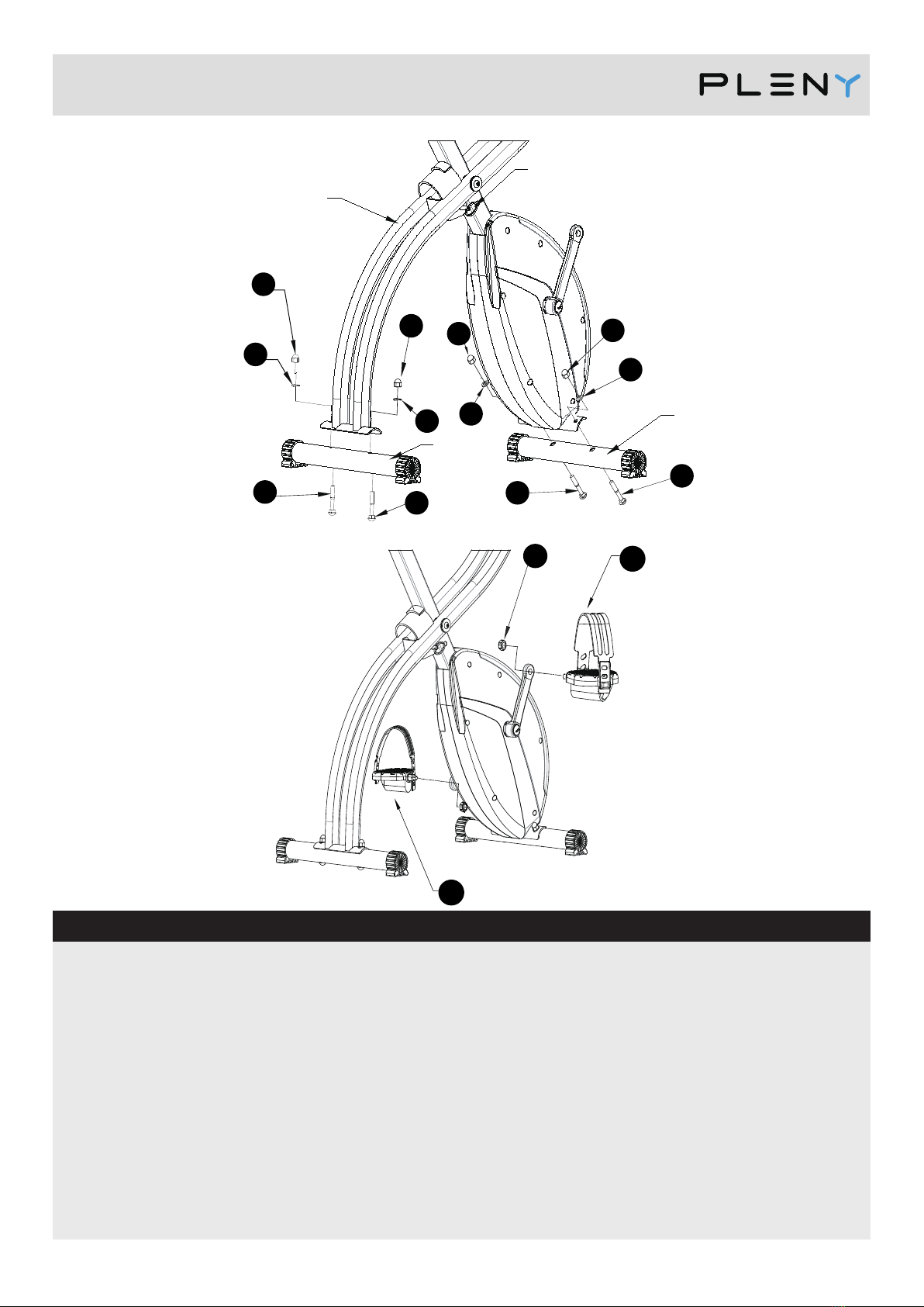
Connect the Handlebar (1) to
the Main Frame (21) using
2 x M8 x 25mm Allen Bolt (7),
2 x M8 Spring Washer (8) and
2 x M8 Curved Washer (59).
ATTENTION!
The Sensor Wire (57) is a
single-wire and the Pulse Wire
(13) is a double-wire. Please
plug these wires to the properly
marked positions at the back of
the Monitor respectively (5).
Attach the Holder of monitor (6)
on the Handlebar (1), insert the
monitor (5) into the Holder of
monitor (6), then tighten the
opening of the holder with one
Screw (11) after adjusting the
angle.
Connect the single Sensor Wire
(57) from the Main Frame to the
back of the Monitor (5) marked
Sensor Wire. The other Pulse
Wire (13) will be connected to
the back of the Monitor (5)
marked Pulse Wire.
WARNING! Heart rate
monitoring systems may be
inaccurate.
Over exercise may result in
serious injury or death.
If you feel faint stop exercising
immediately.
Step 3
The 3 x M8 Nut (17) and 3 x
Saddle Washer (16) are
pre-assembled on the Saddle
(10).
Remove them before the
assembly of the Saddle (10) to
the Saddle Stem Insert (15).
Fix the Saddle (10) to the
Saddle Stem Insert (15) by
re-fitting the 3 x Saddle Washer
(16) and 3 x M8 Nut (17)
previously removed. Attach the
Adjuster Knob (22) into the
saddle support before you slide
the Saddle Stem Insert (15) into
the Main Frame (21), but do not
Step 2
22
21
15
13
21
1
57
10
15
21
6
5
8
5
TM
completely tighten now.
Insert the assembled Saddle
into the main frame. And then
check Page 7 for height
adjustment guide.
16
17
59
8
7
11
57
13

7
Adjustment / Folding away
Adjustment of Seat Height
Adjustment of Resistance level by turning the 16-level tension knob either tothe right (increase) or
left (decrease). PLENY is highly suggest users to start at lower resistance level at the begining.
Folding away your Exercise Cycle
Insert the Locking Pin (27) through the holes to lock the folding position in place as depicted in
the illustration.
Folded dimension of the exercise cycle is 16.15 x 6.7 x 55.2 (H) inch.
Adjustment of Resistance
1
4
7
10
13
16
27
15
22
21
TM
This Adjuster Knob (22) is an Elastic Knob, User can easily pull the knob head to adjust height without
take it off from the main frame. Slightly loosen the Knob and pull the knob head, pull or push the Saddle Stem
Insert (15) to adjust the seat height, then push the knob back and then completely tighten it. Do not pull over
the Max mark for maximum height or push down below MIN mark for minimum height.

8
Installation of Batteries
Remove the Back Cover (A) of the Monitor (5)
and install 2 x AA battery (B) into the battery
compartment. Put the Back cover (A) back to the
Monitor (5).
A
B
5
TM
Workout Area
Free area and training area.
The free area should be no less than 0.6m greater than the training area in the directions from which
the equipment is accessed. The free area must also include the area for emergency dismount.
Where equipment is positioned adjacent to each other the value of the free area may be shared.
0.6m
(Free area)
0.6m
(Free area)
0.6m
(Free area)
0.6m
(Free area)
Training
area
3.7m
PLENY Folding
Exercise Bike

9
Computer Operation
Functions and operations
Specifications
Function
Auto Scan Every 6 seconds
Speed 0.0-99.9 Mile/H
Distance 0.0-999.9 Mile
Time 0:00-99:59 (Minute: Second)
Calories 0-9999 Kcal
Pulse 40-240 BPM
Sensor No-contact magnetic type
Battery type 2 x SIZE-AA (included)
Operation temperature 0˚C ~ +40˚C (32˚F ~ 104˚F)
MODE: This key lets you to select and lock on to a
particular function you want.
.
AUTO ON /OFF: The system turns on when any
key is pressed or when it receives a signal input
from the speed sensor.
The system turns off automatically when the sensor
has no signal input or no key is pressed for
approximately 4 minutes.
RESET: The unit can be reset by either changing the
battery or pressing the mode key for 3 seconds.
MODE: To choose the SCAN or LOCK if you do not
want the scan mode, press the MODE key when the
pointer on the function you want begins blinking.
TIME: Press the MODE key until the pointer
advance to TIME. The total working time will be
shown.
SPEED: Press the MODE key until the pointer
advance to SPEED. The total working time will
be shown.
DISTANCE: Press the MODE key until the pointer
advance to DISTANCE. The distance of each
workout will be displayed.
PULSE: Press the MODE key until pointer advance
to PULSE. User’s current heart rate will be
displayed in beats per minute. Place the palms of
your hands on both of the contact pads (or put
ear-clip to ear), and wait for 30 seconds for the
most accurate reading.
CALORIES: Press the MODE key until the pointer
advance to CALORIES. The calories burned will be
displayed.
Functions
SCAN: Automatic display of the following functions
in the order shown: TIME----SPEED----DISTANCE----
PULSE-----CALORIES (repeat).
Mode
Mode
SCAN
SPEED
DISTANCE
TIME
CALORIES
PULSE
Display
Functions:
SCAN / TIME / SPEED / DISTANCE / PULSE /
CALORIES
TM
Table of contents
Other PLENY Exercise Bike manuals