Pleora Technologies iPORT NTx-Mini User manual

Installing, Uninstalling, and Starting the Software Applications a
PLEORA TECHNOLOGIES INC.
iPORT NTx-Mini
Embedded Video Interface
User Guide

Copyright © 2020 Pleora Technologies Inc.
These products are not intended for use in life support appliances, devices, or systems where malfunction of these products can
reasonably be expected to result in personal injury. Pleora Technologies Inc. (Pleora) customers using or selling these products for
use in such applications do so at their own risk and agree to indemnify Pleora for any damages resulting from such improper use or
sale.
Trademarks
CoreGEV, PureGEV, eBUS, iPORT, vDisplay, AutoGEV, AutoGen, and all product logos are trademarks of Pleora Technologies.
Third party copyrights and trademarks are the property of their respective owners.
Notice of Rights
All information provided in this manual is believed to be accurate and reliable. No responsibility is assumed by Pleora for its use.
Pleora reserves the right to make changes to this information without notice. Redistribution of this manual in whole or in part, by
any means, is prohibited without obtaining prior permission from Pleora.
Document Number
EX001-011-0001, Version 1.0, 11/2/20

i
Table of Contents
About this Guide . . . . . . . . . . . . . . . . . . . . . . . . . . . . . . . . . . . . . . . . . . . . . . . . . . . . . . . . . . . . . . . . . . . . 1
What this Guide Provides . . . . . . . . . . . . . . . . . . . . . . . . . . . . . . . . . . . . . . . . . . . . . . . . . . . . . . . . . . . . . . . . . . . . 2
Documented Product Versions . . . . . . . . . . . . . . . . . . . . . . . . . . . . . . . . . . . . . . . . . . . . . . . . . . . . . . . . . . . . . . . . 2
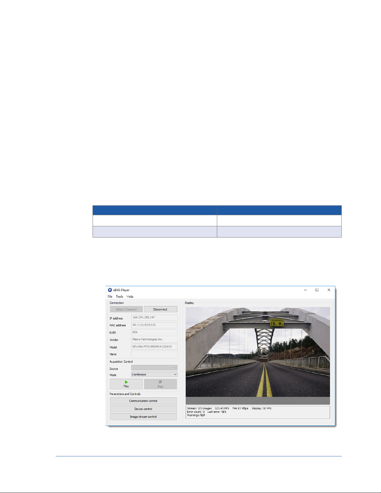
Start Streaming Video . . . . . . . . . . . . . . . . . . . . . . . . . . . . . . . . . . . . . . . . . . . . . . . . . . . . . . . . . . . . . . . . . . . . . . . 2
Related Documents . . . . . . . . . . . . . . . . . . . . . . . . . . . . . . . . . . . . . . . . . . . . . . . . . . . . . . . . . . . . . . . . . . . . . . . . . 3
Further Reading . . . . . . . . . . . . . . . . . . . . . . . . . . . . . . . . . . . . . . . . . . . . . . . . . . . . . . . . . . . . . . . . . . . . . . . . . . . . 3
About the iPORT NTx-Mini Embedded Video Interface . . . . . . . . . . . . . . . . . . . . . . . . . . . . . . . . . . . . . . 5
Model Variants . . . . . . . . . . . . . . . . . . . . . . . . . . . . . . . . . . . . . . . . . . . . . . . . . . . . . . . . . . . . . . . . . . . . . . . . . . . . 6
Feature Set . . . . . . . . . . . . . . . . . . . . . . . . . . . . . . . . . . . . . . . . . . . . . . . . . . . . . . . . . . . . . . . . . . . . . . . . . . . . . . . . 8
Connector Details and Pinouts. . . . . . . . . . . . . . . . . . . . . . . . . . . . . . . . . . . . . . . . . . . . . . . . . . . . . . . .11
Connector Locations . . . . . . . . . . . . . . . . . . . . . . . . . . . . . . . . . . . . . . . . . . . . . . . . . . . . . . . . . . . . . . . . . . . . . . . 12
Mounting the 12-pin Circular Connector to an Enclosure Backplate. . . . . . . . . . . . . . . . . . . . . . . . . . . . . . . . . . . 13
Raw Video 60-Pin FFC/FPC Connector (J5). . . . . . . . . . . . . . . . . . . . . . . . . . . . . . . . . . . . . . . . . . . . . . . . . . . . . 15
Input and Output Signal Levels . . . . . . . . . . . . . . . . . . . . . . . . . . . . . . . . . . . . . . . . . . . . . . . . . . . . . . . . . . . . . 18
Pixel Bus Timing . . . . . . . . . . . . . . . . . . . . . . . . . . . . . . . . . . . . . . . . . . . . . . . . . . . . . . . . . . . . . . . . . . . . . . . . . . 19
Pixel Bus Signals . . . . . . . . . . . . . . . . . . . . . . . . . . . . . . . . . . . . . . . . . . . . . . . . . . . . . . . . . . . . . . . . . . . . . . . . 20
Case 1: FVAL and LVAL are Level-Sensitive . . . . . . . . . . . . . . . . . . . . . . . . . . . . . . . . . . . . . . . . . . . . . . . . . . . 20
Case 2: FVAL and LVAL are Edge-Sensitive . . . . . . . . . . . . . . . . . . . . . . . . . . . . . . . . . . . . . . . . . . . . . . . . . . . 21
Case 3: FVAL is Edge-Sensitive and LVAL is Level-Sensitive . . . . . . . . . . . . . . . . . . . . . . . . . . . . . . . . . . . . . . . 22
Timing Values for All Cases . . . . . . . . . . . . . . . . . . . . . . . . . . . . . . . . . . . . . . . . . . . . . . . . . . . . . . . . . . . . . . . . 22
High-Bandwidth Serial Port: BULK0 . . . . . . . . . . . . . . . . . . . . . . . . . . . . . . . . . . . . . . . . . . . . . . . . . . . . . . . . . . 24
High-Bandwidth Serial: BULK0 UART . . . . . . . . . . . . . . . . . . . . . . . . . . . . . . . . . . . . . . . . . . . . . . . . . . . . . . 24
High-Bandwidth Serial: BULK0 USRT. . . . . . . . . . . . . . . . . . . . . . . . . . . . . . . . . . . . . . . . . . . . . . . . . . . . . . . 25
High Bandwidth Serial: I2C. . . . . . . . . . . . . . . . . . . . . . . . . . . . . . . . . . . . . . . . . . . . . . . . . . . . . . . . . . . . . . . . 26
Standard-Bandwidth Serial Port: UART . . . . . . . . . . . . . . . . . . . . . . . . . . . . . . . . . . . . . . . . . . . . . . . . . . . . . . . . 27
UART Timing . . . . . . . . . . . . . . . . . . . . . . . . . . . . . . . . . . . . . . . . . . . . . . . . . . . . . . . . . . . . . . . . . . . . . . . . . . 27
PLC 20-Pin FFC/FPC Connector (J4). . . . . . . . . . . . . . . . . . . . . . . . . . . . . . . . . . . . . . . . . . . . . . . . . . . . . . . . . . 29
Input and Output Signal Levels . . . . . . . . . . . . . . . . . . . . . . . . . . . . . . . . . . . . . . . . . . . . . . . . . . . . . . . . . . . . . 31
FlexEBoard . . . . . . . . . . . . . . . . . . . . . . . . . . . . . . . . . . . . . . . . . . . . . . . . . . . . . . . . . . . . . . . . . . . . . . . . . . . . . . 31
AdaptRBoard . . . . . . . . . . . . . . . . . . . . . . . . . . . . . . . . . . . . . . . . . . . . . . . . . . . . . . . . . . . . . . . . . . . . . . . . . . . . . 32
Translating Signal Levels . . . . . . . . . . . . . . . . . . . . . . . . . . . . . . . . . . . . . . . . . . . . . . . . . . . . . . . . . . . . . . . . . . 32
AdaptRBoard Signal Specifications . . . . . . . . . . . . . . . . . . . . . . . . . . . . . . . . . . . . . . . . . . . . . . . . . . . . . . . . . . 34
Signal Level Conversions . . . . . . . . . . . . . . . . . . . . . . . . . . . . . . . . . . . . . . . . . . . . . . . . . . . . . . . . . . . . . . . . . . 37
PLC Timing. . . . . . . . . . . . . . . . . . . . . . . . . . . . . . . . . . . . . . . . . . . . . . . . . . . . . . . . . . . . . . . . . . . . . . . . . . . . . . 40
Status LEDs . . . . . . . . . . . . . . . . . . . . . . . . . . . . . . . . . . . . . . . . . . . . . . . . . . . . . . . . . . . . . . . . . . . . . . .41
Power . . . . . . . . . . . . . . . . . . . . . . . . . . . . . . . . . . . . . . . . . . . . . . . . . . . . . . . . . . . . . . . . . . . . . . . . . . . .43
Power Supply Overview . . . . . . . . . . . . . . . . . . . . . . . . . . . . . . . . . . . . . . . . . . . . . . . . . . . . . . . . . . . . . . . . . . . . . 44
Power Signals . . . . . . . . . . . . . . . . . . . . . . . . . . . . . . . . . . . . . . . . . . . . . . . . . . . . . . . . . . . . . . . . . . . . . . . . . . . 44
Power Supply Components . . . . . . . . . . . . . . . . . . . . . . . . . . . . . . . . . . . . . . . . . . . . . . . . . . . . . . . . . . . . . . . . 45
General Design Rules. . . . . . . . . . . . . . . . . . . . . . . . . . . . . . . . . . . . . . . . . . . . . . . . . . . . . . . . . . . . . . . . . . . . . . . 46
Design Options . . . . . . . . . . . . . . . . . . . . . . . . . . . . . . . . . . . . . . . . . . . . . . . . . . . . . . . . . . . . . . . . . . . . . . . . . . . 47
Design 1: Separate Power Supplies for the NTx-Mini and Camera . . . . . . . . . . . . . . . . . . . . . . . . . . . . . . . . . . 47

ii iPORT NTx-Mini Embedded Video Interface User Guide
Design 2: NTx-Mini Supplies Power to the Camera through CAMERA_VIN and/or DVCC (2.5 V) . . . . . . . 48
Design 3: Camera Supplies Power to the NTx-Mini through CAMERA_VIN . . . . . . . . . . . . . . . . . . . . . . . . . 49
Power Consumption . . . . . . . . . . . . . . . . . . . . . . . . . . . . . . . . . . . . . . . . . . . . . . . . . . . . . . . . . . . . . . . . . . . . . . . 50
Signal Specifications. . . . . . . . . . . . . . . . . . . . . . . . . . . . . . . . . . . . . . . . . . . . . . . . . . . . . . . . . . . . . . . . . . . . . . . . 51
Thermal Requirements . . . . . . . . . . . . . . . . . . . . . . . . . . . . . . . . . . . . . . . . . . . . . . . . . . . . . . . . . . . . . .55
Ambient and Junction Temperatures . . . . . . . . . . . . . . . . . . . . . . . . . . . . . . . . . . . . . . . . . . . . . . . . . . . . . . . . . . . 55
Pixel Bus Definitions . . . . . . . . . . . . . . . . . . . . . . . . . . . . . . . . . . . . . . . . . . . . . . . . . . . . . . . . . . . . . . . .57
Mono/RGB/Bayer . . . . . . . . . . . . . . . . . . . . . . . . . . . . . . . . . . . . . . . . . . . . . . . . . . . . . . . . . . . . . . . . . . . . . . . 57
YUV 4:1:1 . . . . . . . . . . . . . . . . . . . . . . . . . . . . . . . . . . . . . . . . . . . . . . . . . . . . . . . . . . . . . . . . . . . . . . . . . . . . . 58
YUV 4:2:2 and 4:4:4 . . . . . . . . . . . . . . . . . . . . . . . . . . . . . . . . . . . . . . . . . . . . . . . . . . . . . . . . . . . . . . . . . . . . . 59
Installing the eBUS Player Toolkit . . . . . . . . . . . . . . . . . . . . . . . . . . . . . . . . . . . . . . . . . . . . . . . . . . . . .61
Installing the eBUS SDK and eBUS Player Toolkit . . . . . . . . . . . . . . . . . . . . . . . . . . . . . . . . . . . . . . . . . . . . . . . . 62
Installing the eBUS Universal Pro Driver. . . . . . . . . . . . . . . . . . . . . . . . . . . . . . . . . . . . . . . . . . . . . . . . . . . . . . . . 62
Connecting to the NTx-Mini and Configuring General Settings . . . . . . . . . . . . . . . . . . . . . . . . . . . . . .63
Confirming Image Streaming. . . . . . . . . . . . . . . . . . . . . . . . . . . . . . . . . . . . . . . . . . . . . . . . . . . . . . . . . . . . . . . . . 64
Configuring the Buffers . . . . . . . . . . . . . . . . . . . . . . . . . . . . . . . . . . . . . . . . . . . . . . . . . . . . . . . . . . . . . . . . . . . . . 65
Providing the NTx-Mini with an IP Address . . . . . . . . . . . . . . . . . . . . . . . . . . . . . . . . . . . . . . . . . . . . . . . . . . . . . 66
Configuring a Temporary IP Address for Initial Communication . . . . . . . . . . . . . . . . . . . . . . . . . . . . . . . . . . . 66
Configuring a Persistent or Automatic (DHCP/LLA) IP Address. . . . . . . . . . . . . . . . . . . . . . . . . . . . . . . . . . . . 67
Configuring the Image Settings . . . . . . . . . . . . . . . . . . . . . . . . . . . . . . . . . . . . . . . . . . . . . . . . . . . . . . . . . . . . . . . 67
Implementing the eBUS SDK . . . . . . . . . . . . . . . . . . . . . . . . . . . . . . . . . . . . . . . . . . . . . . . . . . . . . . . . . . . . . . . . 69
Network Configurations for the NTx-Mini. . . . . . . . . . . . . . . . . . . . . . . . . . . . . . . . . . . . . . . . . . . . . . . .71
Unicast Network Configuration. . . . . . . . . . . . . . . . . . . . . . . . . . . . . . . . . . . . . . . . . . . . . . . . . . . . . . . . . . . . . . . 72
Required Items — Unicast Network Configuration. . . . . . . . . . . . . . . . . . . . . . . . . . . . . . . . . . . . . . . . . . . . . . 72
NTx-Mini Configuration — Unicast Network Configuration . . . . . . . . . . . . . . . . . . . . . . . . . . . . . . . . . . . . . . 73
Multicast Network Configuration . . . . . . . . . . . . . . . . . . . . . . . . . . . . . . . . . . . . . . . . . . . . . . . . . . . . . . . . . . . . . 74
Required Items — Multicast Network Configuration . . . . . . . . . . . . . . . . . . . . . . . . . . . . . . . . . . . . . . . . . . . . 75
Connecting the Hardware and Power. . . . . . . . . . . . . . . . . . . . . . . . . . . . . . . . . . . . . . . . . . . . . . . . . . . . . . . . . 75
Configuring the Devices for a Multicast Network Configuration. . . . . . . . . . . . . . . . . . . . . . . . . . . . . . . . . . . . 76
Storing Images in the NTx-Mini’s Onboard Memory . . . . . . . . . . . . . . . . . . . . . . . . . . . . . . . . . . . . . . .81
High-Bandwidth Bursts . . . . . . . . . . . . . . . . . . . . . . . . . . . . . . . . . . . . . . . . . . . . . . . . . . . . . . . . . . . . . . . . . . . . . 82
Calculating Onboard Memory . . . . . . . . . . . . . . . . . . . . . . . . . . . . . . . . . . . . . . . . . . . . . . . . . . . . . . . . . . . . . . . . 82
Reference: Mechanical Drawings and Material List . . . . . . . . . . . . . . . . . . . . . . . . . . . . . . . . . . . . . . .83
Mechanical Drawings. . . . . . . . . . . . . . . . . . . . . . . . . . . . . . . . . . . . . . . . . . . . . . . . . . . . . . . . . . . . . . . . . . . . . . . 84
NTx-Mini Main Board, Horizontal RJ45 Jack. . . . . . . . . . . . . . . . . . . . . . . . . . . . . . . . . . . . . . . . . . . . . . . . . . 84
NTx-Mini Main Board, Vertical RJ45 Jack . . . . . . . . . . . . . . . . . . . . . . . . . . . . . . . . . . . . . . . . . . . . . . . . . . . . 87
Component Heights . . . . . . . . . . . . . . . . . . . . . . . . . . . . . . . . . . . . . . . . . . . . . . . . . . . . . . . . . . . . . . . . . . . . . 90
AdaptRBoard . . . . . . . . . . . . . . . . . . . . . . . . . . . . . . . . . . . . . . . . . . . . . . . . . . . . . . . . . . . . . . . . . . . . . . . . . . . 92
FlexEBoard . . . . . . . . . . . . . . . . . . . . . . . . . . . . . . . . . . . . . . . . . . . . . . . . . . . . . . . . . . . . . . . . . . . . . . . . . . . . 95
Material List. . . . . . . . . . . . . . . . . . . . . . . . . . . . . . . . . . . . . . . . . . . . . . . . . . . . . . . . . . . . . . . . . . . . . . . . . . . . . . 97
Appendix: Frame Buffer High Watermark . . . . . . . . . . . . . . . . . . . . . . . . . . . . . . . . . . . . . . . . . . . . . . .99

iii
Feature Descriptions . . . . . . . . . . . . . . . . . . . . . . . . . . . . . . . . . . . . . . . . . . . . . . . . . . . . . . . . . . . . . . . . . . . . . . 100
Memory Water Level . . . . . . . . . . . . . . . . . . . . . . . . . . . . . . . . . . . . . . . . . . . . . . . . . . . . . . . . . . . . . . . . . . . . 100
Frame Buffer High Watermark . . . . . . . . . . . . . . . . . . . . . . . . . . . . . . . . . . . . . . . . . . . . . . . . . . . . . . . . . . . . 100
Frame Buffer High Watermark Output Control . . . . . . . . . . . . . . . . . . . . . . . . . . . . . . . . . . . . . . . . . . . . . . . 101
Frame Buffer High Watermark Level Status. . . . . . . . . . . . . . . . . . . . . . . . . . . . . . . . . . . . . . . . . . . . . . . . . . . 102
Timing. . . . . . . . . . . . . . . . . . . . . . . . . . . . . . . . . . . . . . . . . . . . . . . . . . . . . . . . . . . . . . . . . . . . . . . . . . . . . . . . . 103
Configuring the Frame Buffer High Watermark Feature . . . . . . . . . . . . . . . . . . . . . . . . . . . . . . . . . . . . . . . . . . . 104
Configuring the GrbCh0AcqCfgMemoryWaterLevel . . . . . . . . . . . . . . . . . . . . . . . . . . . . . . . . . . . . . . . . . . . 104
Configuring the BufferWatermarkLevel . . . . . . . . . . . . . . . . . . . . . . . . . . . . . . . . . . . . . . . . . . . . . . . . . . . . . . 105
Configuring the BufferWatermarkLevelOutputControl. . . . . . . . . . . . . . . . . . . . . . . . . . . . . . . . . . . . . . . . . . 105
Sample Waveforms. . . . . . . . . . . . . . . . . . . . . . . . . . . . . . . . . . . . . . . . . . . . . . . . . . . . . . . . . . . . . . . . . . . . . . . . 106
Example Application Code for Frame Buffer High Watermark . . . . . . . . . . . . . . . . . . . . . . . . . . . . . . . . . . . . . . 108
Technical Support . . . . . . . . . . . . . . . . . . . . . . . . . . . . . . . . . . . . . . . . . . . . . . . . . . . . . . . . . . . . . . . . 109
Copyright Information. . . . . . . . . . . . . . . . . . . . . . . . . . . . . . . . . . . . . . . . . . . . . . . . . . . . . . . . . . . . . . . . . . . . . 110


About this Guide 1
Chapter 1
About this Guide
The iPORT™ NTx-Mini Embedded Video Interface provides a flexible and economical solution for
camera companies to integrate Gigabit Ethernet (GigE) connectivity into almost any industrial camera.
The NTx-Mini supplies these features in an ultra-small footprint with low power consumption and
flexible mounting options.
The following topics are covered in this chapter:
•“What this Guide Provides” on page 2
•“Documented Product Versions” on page 2
•“Start Streaming Video” on page 2
•“Related Documents” on page 3
•“Further Reading” on page 3

2 About this Guide
What this Guide Provides
This guide provides you with all of the information you need to connect the NTx-Mini to your sensor
and related electronics to create a camera or other imaging device. In this guide you will find a product
overview, connector details, and mechanical drawings, along with instructions for installing the Pleora
software, connecting the device, and performing general configuration tasks to properly display video.
The last chapter of this guide provides Technical Support contact information for Pleora Technologies.
Documented Product Versions
This guide covers the following product versions. The features and functionality documented in this
guide may vary if you are using an earlier or later version of the product.
Start Streaming Video
If you want to quickly start streaming video, you can go to “Confirming Image Streaming” on page 64.
Table 1: Documented Product Versions
Product Version documented in this guide...
iPORT NTx-Mini Embedded Video Interface 2.5.29
eBUS SDK and eBUS Player Toolkit 6.1

3About this Guide
Related Documents
The iPORT NTx-Mini Embedded Video Interface User Guide is complemented by the following Pleora
Technologies documents, which are available on the Pleora Support Center at supportcenter.pleora.com:
•eBUS Player User Guide
•Programmable Logic Controller Reference Guide
You can consult the following additional documentation:
•Altera Application Note - AN447, available from Altera
Further Reading
Although not required to successfully use the iPORT NTx-Mini Embedded Video Interface User Guide, you
can find details about industry-related standards and naming conventions in the following documents:
•GigE Vision Standard, available from the Automated Imaging Association (AIA) at
www.visiononline.org
•GenICam Standard Features Naming Convention available from the European Machine Vision
Association (EMVA) at www.emva.org.


6 About the iPORT NTx-Mini Embedded Video Interface
Model Variants
The following NTx-Mini variants are available and include the following parts.
Table 2: NTx-Mini Models
Order code Model Quantity
904-3011 iPORT NTx-Mini Main board, vertical RJ45 jack
iPORT NTx-Mini Main board, vertical RJ45 jack 1
904-3013 iPORT NTx-Mini in-camera set, vertical RJ45 jack
iPORT NTx-Mini Main board, vertical
RJ45 jack
1
AdaptRBoard
1
FlexEBoard
1
904-3014 iPORT NTx-Mini Development kit, vertical RJ45 jack
iPORT NTx-Mini Main board, vertical RJ45 jack 1
AdaptRBoard 1
FlexEBoard 1
Prober board 1
Flat flex cables 4
Power supply 1
Gigabit Ethernet desktop NIC 1
Ethernet cable 1
12-pin circular connector soldered on FlexEBoard 1
eBUS SDK USB stick 1
904-3213 iPORT NTx-Mini Main board, horizontal RJ45 jack
iPORT NTx-Mini Main board, horizontal
RJ45 jack
1
904-3214 iPORT NTx-Mini board set, horizontal RJ45 jack
iPORT NTx-Mini Main board, horizontal
RJ45 jack
1
AdaptRBoard 1

7About the iPORT NTx-Mini Embedded Video Interface
904-3215 iPORT NTx-Mini in-camera set, horizontal RJ45 jack
iPORT NTx-Mini Main board, horizontal
RJ45 jack
1
AdaptRBoard 1
FlexEBoard 1
904-3216 iPORT NTx-Mini Development kit, horizontal RJ45 jack
iPORT NTx-Mini Main board, horizontal RJ45 jack 1
AdaptRBoard 1
FlexEBoard 1
Prober board 1
Flat flex cables 4
Power supply 1
Gigabit Ethernet desktop NIC 1
Ethernet cable 1
12-pin circular connector soldered on FlexEBoard 1
eBUS SDK USB stick 1

8 About the iPORT NTx-Mini Embedded Video Interface
Feature Set
Table 3: Feature Set
Networked Video Connectivity Solutions
iPORT™ Embedded
Video Interface
• Highly reliable, 1 Gb/s data
transfer rate with low, end-to-end
latency
• OEM board
• 32 MB of DDR2 RAM
eBUS™ SDK • eBUS Universal Pro driver
• Sample applications, which
demonstrate multi-device network
connectivity
• Driver installation tool
• eBUS Player application and
sample code, which demonstrates
advanced API features
• Documentation
AutoGEV™ XML
Generation Tool
• Unique GenICam™ XML
management tool for seamless
GenICam integration
GigE Vision ®• Compliant to version 1.2
• Fully compliant firmware load
• Guarantees delivery of all packets
• Comprehensive data transfer
diagnostics
Connectors
FlexEBoard • 12-pin (Hirose HR10A-10R-
12PB(71))
• 20-pin FPC (Hirose FH12-20S-
0.5SH)
AdaptRBoard • 40-pin (Hirose DF12(3.5)-40DP-
0.5V(86))
Network • Available with horizontally or
vertically mounted RJ-45 on the
NTx-Mini Main Board
Camera Head
Interface
• 60-pin (Molex 501951-6000)
PLC • 20-pin FPC (Wurth
687120149028)
Networking Features
GigE-based • 10/100/1000 Mb/s
• IEEE 802.3 (Ethernet), IPv4,
IGMPv.2, UDP, and ICMP (ping)
• Long reach: 100 m point-to-
point, further with Ethernet
switches or Fiber
GigE Vision Protocol • Guarantees delivery of all
packets
• Comprehensive data transfer
diagnostics
Unconditional
streaming
• Continue streaming when the
controlling application
becomes unavailable or when
the state of the network
changes
Multicast capability • Enables advanced distributed
processing and control
architectures
Characteristics
Size (L x W x H) • 42.0 x 42.0 x 21.6 mm
(horizontal version)
• 42.0 x 42.0 x 24.3 mm
(vertical version)
Operating
temperature
• Commercial temperature
grade components are used,
temperature performance will
vary depending on the user’s
thermal design*
Storage
temperature
• -40°C to 85°C
Power supply • Nominally 4.5V to 16V**
Power consumption • From 1.6W (input voltage and
temperature dependent)
MTBF at 40°C • 2,382,545 hours
ECCN • 5A991.b
* Case and junction temperature limits vary by IC device.
See “Thermal Requirements” on page 55.
** See “Power Consumption” on page 50 for details.

9About the iPORT NTx-Mini Embedded Video Interface
Table 3:
Feature Set (Continued)
Programmable Logic Features
4 inputs
4 outputs to PLC
connector
4 outputs to raw video
connector (2.5V
LVCMOS/LVTTL)
• Provides a flexible, general-purpose
interface with the AdaptRBoard in
the In-Camera Set and
Development Kit
• Users can design their own
AdaptRBoard for additional
flexibility
• Allows synchronization of multiple
devices or system elements
• Flexible triggering capabilities,
including Boolean combinations,
deserialized camera control
signals, encoders, and time stamps
• Built-in debouncers
1 RS-232 serial link • Serial control of external devices
via PC application over the GigE link
• Can be bridged to an internal UART
serial link with a user-designed
AdaptRBoard
2 UART serial links**
(LVCMOS/LVTTL)
• Serial control of camera and other
devices via PC application over the
GigE link
Delayer, rescaler,
general-purpose
counter
• Allows full synchronization of video
source and other system elements
Timestamp trigger,
counter, and reset
• Allows system actions to be
triggered based on timestamps
• Allows resets to be broadcast to all
iPORT video interfaces in the
system from a host
Host interrupts • Allows host to be interrupted based
on events on any input or internal
signal
** One UART serial link is available for GenICam integration using
the AutoGEV XML generation tool
Data Acquisition Features
Raw video
connector (2.5V
LVCMOS/LVTTL)
• Compatible with internal
camera signal levels
Integrated
acquisition engine
• Area scan and line scan
• Pixel clock: 20 MHz to 90 MHz
• Pixel depth: 8, 10, 12, 14, 16,
and 24 bits
• Pixel formats: Mono, BayerGR/
RG/GB/BG, RGB, BGR, YUV,
Raw
• Image height: 1 to 16,383
pixels
• Image width: 8 to 16,376
pixels
• Tap support: 1 and 2 taps
• Tap reconstruction:
interleaved only
• Window/region of interest
Free running or
externally triggered
• Flexible acquisition modes
• Continuous
• SingleFrame
• MultiFrame
• ContinuousRecording
• ContinuousReadout
• SingleFrameRecording
• SingleFrameReadout
Static configuration • Configuration settings are
saved to onboard Flash
memory leveraging User Sets
from GenICam


Connector Details and Pinouts 11
Chapter 3
Connector Details and Pinouts
This chapter describes the connectors on the NTx-Mini, including pinouts and signal information. It also
provides details about the FlexEBoard, which connects to the PLC 20-pin connector to provide power
and external signals. This chapter also provides timing information for the NTx-Mini’s pixel bus and
Programmable Logic Controller (PLC).
The following topics are covered in this chapter:
•“Connector Locations” on page 12
•“Mounting the 12-pin Circular Connector to an Enclosure Backplate” on page 13
•“Raw Video 60-Pin FFC/FPC Connector (J5)” on page 15
•“Pixel Bus Timing” on page 19
•“High-Bandwidth Serial Port: BULK0” on page 24
•“Standard-Bandwidth Serial Port: UART” on page 27
•“PLC 20-Pin FFC/FPC Connector (J4)” on page 29
•“FlexEBoard” on page 31
•“AdaptRBoard” on page 32
•“PLC Timing” on page 40

12 Connector Details and Pinouts
Connector Locations
The following figure and table describe the NTx-Mini connectors. The NTx-Mini vertical version is
shown.
FlexEBoard (front view)
Main board
(front view)
Main board
(back view)
J5
J1
J4
J1
AdaptRBoard
J1
Pin 1
Pin 1
Pin 1
J2
Pin 1
FlexEBoard (back view)
U1 Pin 1
Table 4: Connector Summary
ID Location Type Description
J1 Main board RJ-45 Ethernet connector
Interfaces the NTx-Mini to Ethernet networks, as specified in IEEE 802.3.
The Ethernet interface can operate at 100 or 1000 Mbps. However, the
“Feature Set” on page 8 mentions 10, 100, and 1000. Supports Internet
Protocol Version 4 (IPv4).
J2 Main board 40-pin connector Connects to an adapter board, such as the Pleora AdaptRBoard, routing
signals to and from the adapter board for conversion or level translation.
J5 Main board 60-pin user circuitry
connector
Interfaces directly to the camera head or other external device.
J4 Main board 20-pin connector Connects to the FlexEBoard with a 20-pin FFC cable, providing power and
external signals. You can connect a 20-pin FFC cable to the FlexEBoard
board or to your own board (for example, if you need optoisolated GPIOs).
J1 FlexEBoard 12-pin circular connector Provides power and external signals, such as GPIO and serial
communication, to the NTx-Mini.
Receives 4.5V to 12V of unfiltered DC input.
U1 FlexEBoard 20-pin connector Connects to the Main board with a 20-pin FFC cable, providing power and
external signals.
J1 AdaptRBoard 40-pin connector Receives internal signal levels (LVTTL) which are converted to signal levels
(TTL, optoisolators, LVDS, and so on) by the AdaptRBoard (or your own
custom-designed adapter board). After the levels are converted, they are
routed to the 20-pin connector.

13Connector Details and Pinouts
Mounting the 12-pin Circular Connector to an Enclosure
Backplate
The removable 12-pin circular connector and the FlexEBoard, which provide power and external signals
to the NTx-Mini, are suitable for mounting to a client-sourced enclosure.
To mount the 12-pin circular connector to an enclosure backplate
1. Insert the 12-pin circular connector through the external side of the backplate.
2. Secure with a washer and hex nut.
3. Connect the FlexEBoard (12 holes) to the base pins of the 12-pin circular connector through the
internal side of the backplate.
12-pin connector
FlexEBoard
12-pin circular connector
Insertion
Lock washer
Hex nut
FlexEBoard
Pins (soldered to FlexEBoard)
20-pin FFC cable
Enclosure interior
Backplate of client-sourced enclosure

14 Connector Details and Pinouts
4. Assemble the 12-pin circular connector to the FlexEBoard by lining up the pins with the
FlexEBoard.
5. Solder the pins of the connector to the FlexEBoard for a secure connection.
When oriented correctly, the tab on the 12-pin connector aligns with the arrow marker on the FlexEBoard.
The following figures show the pin locations, and also show the tab and arrow marker.
Tab
12-pin circular connector
FlexEBoard and 12-pin
Tab location
12-pin circular
circular connector (assembled)
connector
FlexEBoard (unassembled)
Arrow
marker
(approximate)
Tab
Table of contents
Other Pleora Technologies Recording Equipment manuals