Pilz PSEN ix1 User manual

- 1 -
Die Schnittstelle PSEN ix1
Mit Hilfe der Schnittstelle PSEN ix1 lassen
sich mehrere Sicherheitsschalter oder
Positionsschalter an Sicherheitsschaltgeräte
der Serie PNOZ anschließen und auswerten.
An das PSEN ix1 dürfen angeschlossen
werden:
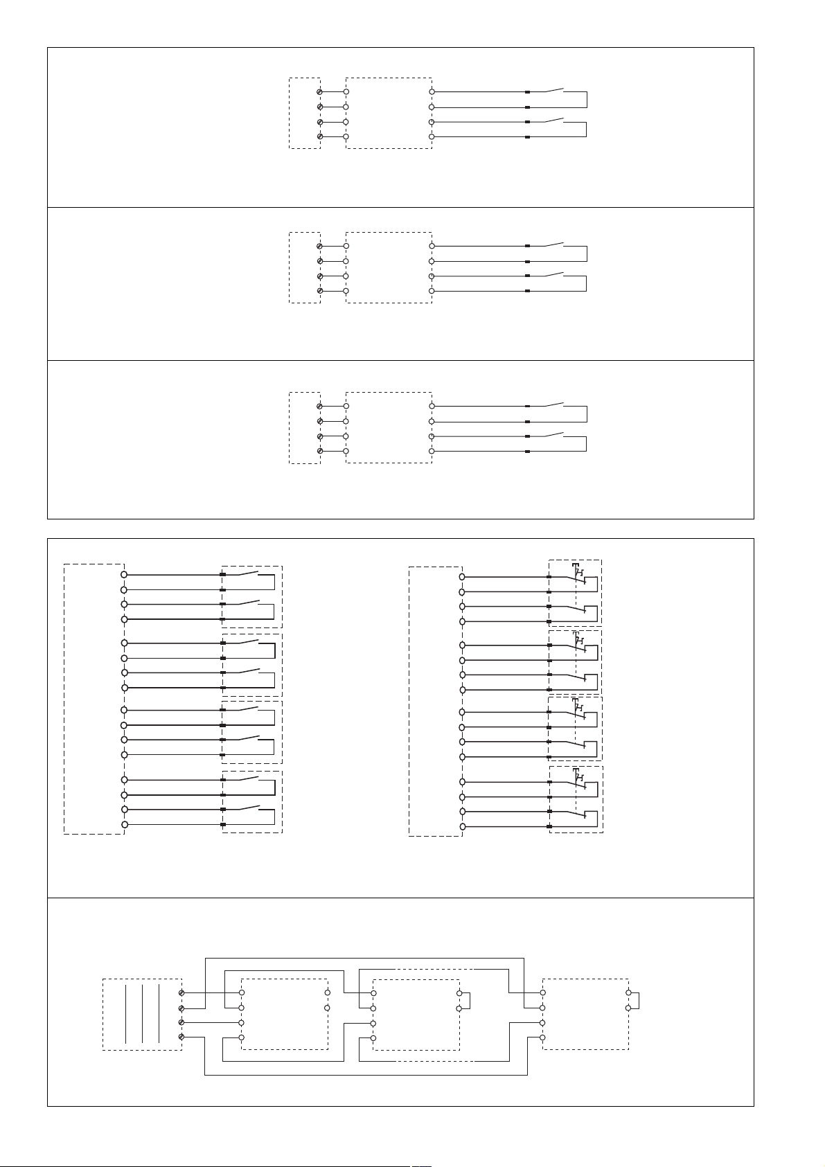
• Sicherheitsschalter PSEN 1.1a-22, PSEN
1.1b-22, PSEN 1.1b-25, PSEN 1.1p-12,
PSEN 1.1p-22, PSEN 1.2p-22, PSEN
1.2p-25, PSEN ma 1.3a-22, PSEN ma
1.3b-22, PSEN ma 1.3b-25
• Positionsschalter mit Schließer-/Schließer-
Kombination
• Not-Halt-Taster mit Öffner-/Öffner-
Kombination
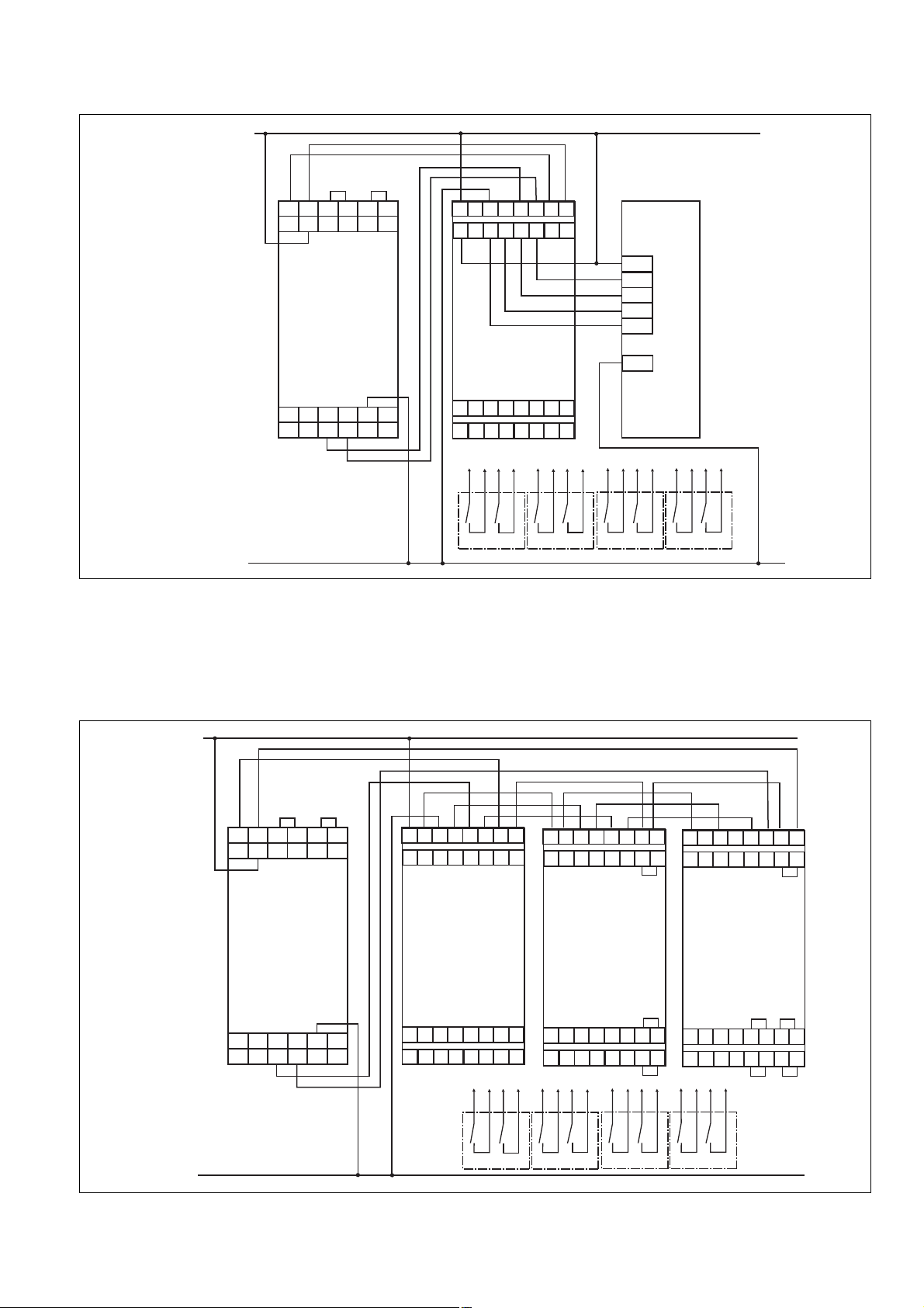
Das PSEN ix1 darf nur an Auswertegeräte
angeschlossen werden, die in der Tabelle im
Abschnitt "Anschlüsse" aufgeführt sind.
Wichtig: Durch die Reihenschaltung
von PSENmag verringert sich der
mögliche Diagnosedeckungsgrad und
dadurch die maximal erreichbaren
Sicherheitsklassifizierungen nach:
•EN 60947-5-3 von PDF-M auf PDF-S
•EN ISO 13849-1 von PLe auf PLc
•EN 62061 von SIL3 auf SIL1
•EN 954-1 von Kat.4 auf Kat.3
Zu Ihrer Sicherheit
Die Schnittstelle PSEN ix1 erfüllt alle
notwendigen Bedingungen für einen sicheren
Betrieb.
Beachten Sie jedoch nachfolgend aufge-
führte Sicherheitsbestimmungen:
• Installieren und nehmen Sie das Gerät nur
dann in Betrieb, wenn Sie mit dieser
Betriebsanleitung und den geltenden
Vorschriften über Arbeitssicherheit und
Unfallverhütung vertraut sind.
• Verwenden Sie das Gerät nur gemäß
seiner Bestimmung. Beachten Sie dazu
auch die Werte im Abschnitt "Technische
Daten".
• Halten Sie beim Transport, bei der
Lagerung und im Betrieb die Bedingungen
nach EN 60068-2-6, 01/00 ein (siehe
"Technische Daten").
• Nehmen Sie keine eigenmächtigen
Umbauten vor.
Beachten Sie unbedingt die Warnhinweise in
den anderen Abschnitten dieser Anleitung.
Diese Hinweise sind optisch durch Symbole
hervorgehoben.
Wichtig: Beachten Sie die Sicher-
heitsbestimmungen, sonst erlischt
jegliche Gewährleistung.
Zulassungen
The interface PSEN ix1
The PSEN ix1 interface enables several
safety switches or position switches to be
connected to safety gate monitors or
programmable safety systems and
evaluated.
The following may be connected to the PSEN
ix1:
• Safety switches PSEN 1.1a-22, PSEN
1.1b-22, PSEN 1.1b-25, PSEN 1.1p-12,
PSEN 1.1p-22, PSEN 1.2p-22, PSEN
1.2p-25, PSEN ma 1.3a-22, PSEN ma
1.3b-22, PSEN ma 1.3b-25
• Position switches with N/O / N/O
combination in safety circuits
• E-STOP button with N/C / N/C
combination
The PSEN ix1 may only be connected to
evaluation devices that are listed in the table
under section "Connections".
Notice: Connecting the PSENmag in
series reduces the potential diagnostic
coverage and therefore the maximum
achievable safety classifications in
accordance with:
• EN 60947-5-3 from PDF-M to PDF-S
• EN ISO 13849-1 from PLe to PLc
• EN 62061 from SIL3 to SIL1
• EN 954-1 from Cat.4 to Cat.3
For your safety
The PSEN ix1 interface meets all the
necessary conditions for safe operation.
However, always ensure the following safety
requirements are met:
• Only install and commission the unit if you
are familiar with the information in these
operating instructions, as well as the
relevant regulations concerning health and
safety at work and accident prevention.
• Only use the unit for the purpose for which
it is intended. Please note also the values
stated in the "Technical details" section.
• Transport, storage and operating
conditions should all conform to EN 60068-
2-6, 01/00 (see "Technical details").
• Do not make any unauthorised
modifications.
You must observe the warning notes given in
other parts of these operating instructions.
These notes are highlighted via symbols.
Notice: Failure to comply with the
safety requirements will render the
guarantee invalid.
Approvals
Interfaccia PSEN ix1
L'interfaccia PSEN ix1 permette il collega-
mento ed il controllo di interruttori di sicurez-
za e di posizione a moduli di sicurezza
PNOZ.
All’interfaccia PSEN ix1 è possibile collegare:
• Gli interruttori di sicurezza PSEN 1.1a-22,
PSEN 1.1b-22, PSEN 1.1b-25, PSEN
1.1p-12, PSEN 1.1p-22, PSEN 1.2p-22,
PSEN 1.2p-25, PSEN ma 1.3a-22, PSEN
ma 1.3b-22, PSEN ma 1.3b-25
• Gli interruttori di posizione con combina-
zione contatto NA/NA
• I pulsanti di arresto di emergenza con
combinazione contatto NC/NC
Il PSEN ix1 si può collegare soltanto ai
dispositivi di controllo elencati nella tabella
nella sezione "Collegamenti".
Importante: il collegamento in serie di
PSENmag riduce la copertura diagno-
stica possibile e di conseguenza le
classificazioni di sicurezza massime
ottenibili come da:
•EN 60947-5-3 da PDF-M a PDF-S
•EN ISO 13849-1 da PLe a PLc
•EN 62061 da SIL3 a SIL1
•EN 954-1 da cat. 4 a cat. 3
Per la vostra sicurezza
L’interfaccia PSEN ix1 soddisfa tutte le
condizioni necessarie per un funzionamento
sicuro.
È tuttavia necessario osservare le seguenti
norme di sicurezza:
• Installare e mettere in funzione il dispositi-
vo solo se si conoscono bene le presenti
istruzioni per l’uso e le disposizioni vigenti
relative alla sicurezza di lavoro e
all’antinfortunistica.
• Utilizzare il dispositivo per i soli scopi cui è
destinato. Osservare anche i valori indicati
nel paragrafo "Dati tecnici".
• Durante il trasporto, l’immagazzinamento
e il funzionamento attenersi alle
condizioni prescritte dalla norma
EN 60068-2-6, 01/00 (vedi "Dati tecnici").
• Non apportare modifiche non autorizzate.
Osservare le avvertenze presenti nelle altre
sezioni delle presenti istruzioni. Tali indica-
zioni sono evidenziate mediante simboli.
Importante: Osservare le disposizioni
per la sicurezza, poiché in caso
contrario decadrà qualsiasi diritto di
garanzia.
Certificazioni
20950-IT-06
PSEN ix1
4D Betriebsanleitung
4GB Operating instructions
4I Istruzioni per luso

- 2 -
Gerätebeschreibung
Gerätemerkmale:
• Reihenschaltung von max. 13 PSEN ix1
möglich
• Anschlussmöglichkeit für
- max. 50 Sicherheitsschalter/Positions-
schalter mit Schließer-/Schließer-
Kombination
- oder max. 50 Not-Halt-Taster mit Öffner-
/Öffner-Kombination
• Statusanzeigen für den Schaltzustand der
Schließerkreise der angeschlossenen
Sensoren
• 4 Diagnoseausgänge zur Anzeige oder
Auswertung des Schaltzustands der
Schließerkreise über externe LEDs oder
eine Steuerung
Funktionsbeschreibung
Das PSEN ix1 schaltet die angeschlossenen
Sicherheitsschalter/Positionsschalter in
Reihe.
Schnittstelle montieren
Achtung! Montieren Sie das Gerät in
einen Schaltschrank mit einer
Schutzart von mindestens IP54.
• Befestigen Sie das Gerät mit Hilfe des
Rastelements auf der Rückseite auf einer
Normschiene.
• Sichern Sie das Gerät auf einer senk-
rechten Tragschiene (35 mm) durch ein
Halteelement (z. B. Endhalter oder
Endwinkel)
Gerät in Betrieb nehmen
Betriebsbereitschaft herstellen
• Legen Sie die Versorgungspannung an:
Klemme A1: + 24 V DC
Klemme A2: 0 V
• Schließen sie die Geräte der Serie
PNOZ X, PNOZsigma, PNOZpower oder
PNOZelog an. Beachten Sie die Betriebs-
anleitung der entsprechenden Geräte.
• Verbinden Sie das PSEN ix1 mit einem
der genannten Sicherheitsschaltgeräte wie
in der folgenden Tabelle angegeben.
• Verbinden Sie die Sicherheitsschalter/
Positionsschalter mit dem PSEN ix1.
Descrizione del dispositivo
Caratteristiche del dispositivo:
• Possibile collegamento in serie di
max. 13 PSEN ix1
• Possibilità di collegamento per
- max. 50 interruttori di sicurezza/
posizione con contatti NA/NA
- oppure max. 50 pulsanti di arresto
di emergenza con contatti NC/NC
• Indicatori di stato per lo stato di
commutazione dei circuiti di chiusura
dei sensori collegati
• 4 uscite di diagnostica per la
visualizzazione o valutazione degli stati di
commutazione dei circuiti di chiusura
tramite LED esterni o un sistema di
controllo
Descrizione del funzionamento
L’interfaccia PSEN ix1 attiva in serie gli
interruttori di sicurezza/posizione collegati.
Montaggio dell’interfaccia
Attenzione! Il dispositivo va montato
in un armadio elettrico con un tipo di
protezione corrispondente almeno al
grado IP 54.
•
Fissare il dispositivo su una guida DIN con
l’aiuto dell’elemento a scatto situato sul retro.
• Fissare il dispositivo su una guida verticale
(35 mm) per mezzo di supporti quali ad es.
staffe di fissaggio o angoli terminali.
Messa in funzione del dispositivo
Preparazione all’uso
• Applicare la tensione di alimentazione:
Morsetto A1: + 24 V DC
Morsetto A2: 0 V
• Collegare i dispositivi della serie
PNOZ X, PNOZsigma, PNOZpower o
PNOZelog. Osservare le indicazioni
riportate nelle istruzioni per l’uso dei
rispettivi dispositivi.
• Collegare l’interfaccia PSEN ix1 con uno
dei moduli di sicurezza indicati come
riportato nella seguente tabella.
• Collegare gli interruttori di sicurezza/
posizione all’interfaccia PSEN ix1.
Unit description
Unit features:
• Connection in series for max. 13 PSEN ix1
possible
• Connection for
- max. 50 safety switches /position switch
with N/O / N/O combination
- or max. 50 E-STOP buttons with N/C /
N/C combination
• Status indicators for the switch status of
the N/O circuits of the connected switches
• 4 diagnostic outputs to display or evaluate
the switch status of the N/O circuits via
external LEDs or a PLC
Innenschaltbild Internal wiring diagram Schema interno di collegamento
2A1
11 12 13 14 21 22 23 24 31 32 33 34 41 42 43 44
3Y8 4 Y1 Y2 Y3 Y4
A1 A2 A2
POWER FAULT
S1 S2 S3 S4
1Y9 Y5 Y6
K1
K2
K3
K4
K1 K2 K3 K4
Vcc
Vcc Vcc Vcc Vcc
K1 K2 K3 K4
Ri
Function description
The PSEN ix1 switches the connected safety
switches /position switches in series.
Installing the interface
Caution!The unit should be installed
in a control cabinet with a protection
type of at least IP54.
• Use the notch on the back of the unit to
attach it to a DIN rail.
• Secure the unit on a vertical DIN rail (35
mm) using a retaining bracket or end angle
Commissioning the unit
Preparing for operation
• Connect the supply voltage:
Terminal A1: + 24 V DC
Terminal A2: 0 V
• Connect the units of the PNOZ X,
PNOZsigma, PNOZpower or PNOZelog
series. Please refer to the operating
instructions for the respective unit.
• Connect the PSEN ix1 with one of the
named safety relays as shown in the
following table.
• Connect the safety switches/position
switches to the PSEN ix1.

- 3 -
Wichtig: Beachten Sie beim
Anschluss von weniger als 4
Sicherheitsschaltern/Positions-
schaltern an einem PSEN ix1: freie
Schließerkontakte überbrücken.
• Bei Anschluss von mehr als 4 Sicherheits-
schaltern/Positionsschaltern: PNOZ ix1 in
Reihe schalten (siehe Abbildung "Reihen-
schaltung von PSEN). Ab dem zweiten
PSEN ix1 Y8-Y9 brücken.
Achtung! Durch elektrostatische
Entladung können Bauteile des
Geräts beschädigt werden. Sorgen
Sie für Entladung, bevor Sie das
Gerät berühren, z. B. durch
Berühren einer geerdeten, leit-
fähigen Fläche oder durch Tragen
eines geerdeten Armbands.
Anschluss an Auswertegerät über
Schnittstelle PSEN ix1
Achtung! An den Klemmen 13/14,
23/24, 33/34 und 43/44, darf der
Leitungswiderstand maximal
30 Ohm betragen.
Notice: When connecting less than 4
safety switches/position switches,
please note: link out the free N/O
contacts on the PSEN ix1.
• When more than 4 safety switches/position
switches are connected: Connect PNOZ
ix1 in series (see illustration "Connecting
PSEN ix1 in series"). From the second
PSEN ix1, link Y8-Y9.
Caution! Electrostatic discharge
can damage components on the
unit. Ensure against discharge
before touching the unit, e.g. by
touching an earthed, conductive
surface or by wearing an earthed
armband.
Connection to evaluation device via PSEN
ix1 interface
Caution! The cable resistance at
terminals 13/14, 23/24, 33/34 and
43/44 may be a maximum of
30 Ohm.
Importante: se si collegano meno di 4
interruttori di sicurezza/posizione a
un’interfaccia PSEN ix1: ponticellare i
contatti NA liberi.
• Se si collegano più di 4 interruttori di
sicurezza/posizione: collegare in serie i
dispositivi PNOZ ix1 (v. la figura "Collega-
mento in serie di PSEN"). Cavallottare a
partire dal secondo PSEN ix1 Y8-Y9.
Attenzione! Le scariche elettro-
statiche possono danneggiare i com-
ponenti del dispositivo. Scaricare
l’energia elettrostatica dal proprio
corpo prima di toccare il dispositivo,
ad es. toccando una superficie
conduttiva collegata a terra, oppure
indossando un bracciale con messa
a terra.
• PNOZ s3
• PNOZ s4
• PNOZ s5
• PNOZ p1p
• PNOZ X2
• PNOZ X2P
• PNOZ X2.1
(nur 24 V DC)
• PNOZ X2.2
• PNOZ X2.3P
• PNOZ X2.7P
• PNOZ X2.8P
• PNOZ X2C
• PNOZ X2.1C
(nur 24 V DC)
• PNOZ X4
• PNOZ X8P
• PNOZ X9
• PNOZ X9P
• PNOZ X10
• PNOZ X10.1
• PNOZ X 10.11P
• PNOZ Ex
• PNOZ e1.1p
• PNOZ e1vp
• PNOZ e6.1p
• PNOZ e6vp
S11
S12
S21
S22
blau/blue/blu
weiß/white/bianco
braun/brown/marrone
schwarz/black/nero
1
2
3
4
11
12
13
14
1
2
3
4
PSEN ix1
• PSEN 1.1a-22
• PSEN 1.1b-22
• PSEN 1.1b-25
• PSEN 1.1p-12
• PSEN 1.1p-22
• PSEN 1.2p-22
• PSEN 1.2p-25
• PSEN ma 1.3a-22
• PSEN ma 1.3b-22
• PSEN ma 1.3b-25
Collegamento al dispositivo di controllo
tramite interfaccia PSEN ix1
Attenzione! Sui morsetti 13/14,
23/24, 33/34 e 43/44, la resistenza
massima consentita per il
conduttore è di 30 ohm.
• PNOZ X5
• PNOZ X5J
• PNOZ 11
• PNOZ 16
• PNOZ X11P
• PNOZ X13
• PNOZ X2.5P
• PNOZ X3
• PNOZ X3.1
• PNOZ X3P
• PNOZ X3.10P
• PNOZ XV2
• PNOZ XV2P
• PNOZ XV3
• PNOZ XV3P
S11
S12
S11
S22
blau/blue/blu
weiß/white/bianco
braun/brown/marrone
schwarz/black/nero
1
2
3
4
11
12
13
14
1
2
3
4
PSEN ix1
S31
S32
S21
S22
blau/blue/blu
weiß/white/bianco
braun/brown/marrone
schwarz/black/nero
1
2
3
4
11
12
13
14
1
2
3
4
PSEN ix1
• PSEN 1.1a-22
• PSEN 1.1b-22
• PSEN 1.1b-25
• PSEN 1.1p-12
• PSEN 1.1p-22
• PSEN 1.2p-22
• PSEN 1.2p-25
• PSEN ma 1.3a-22
• PSEN ma 1.3b-22
• PSEN ma 1.3b-25
• PSEN 1.1a-22
• PSEN 1.1b-22
• PSEN 1.1b-25
• PSEN 1.1p-12
• PSEN 1.1p-22
• PSEN 1.2p-22
• PSEN 1.2p-25
• PSEN ma 1.3a-22
• PSEN ma 1.3b-22
• PSEN ma 1.3b-25
• PNOZ X2.9P
S11
S12
S11
S52
blau/blue/blu
weiß/white/bianco
braun/brown/marrone
schwarz/black/nero
1
2
3
4
11
12
13
14
1
2
3
4
PSEN ix1
• PSEN 1.1a-22
• PSEN 1.1b-22
• PSEN 1.1b-25
• PSEN 1.1p-12
• PSEN 1.1p-22
• PSEN 1.2p-22
• PSEN 1.2p-25
• PSEN ma 1.3a-22
• PSEN ma 1.3b-22
• PSEN ma 1.3b-25

- 4 -
1
2
3
4
9
81
2
3
4
9
81
2
3
4
9
8
PSEN ix1PSEN ix1PSEN ix1
PNOZ X, PNOZsigma,
PNOZpower, PNOZelog
S21 S11 S21 S12
S22 S22 S22 S24
S11 S11 S31 S11
S12 S12 S32 S12
Reihenschaltung von PSEN ix1 Connecting PSEN ix1in series
Collegamento in serie dell’interfaccia PSEN ix1
max. 13 PSEN ix1, Y8-Y9 ab zweitem
Gerät brücken
max. 13 PSEN ix1, link Y8-Y9 from the
second device
cavallottare max. 13 interfacce PSEN ix1,
Y8-Y9 a partire dal secondo dispositivo
Sicherheitssensoren/
Positionsschalter
safety switches/
position switches
sensori di sicurezza/
interruttori di posizione
PSEN ix1
1
2
3
4
blau/blue/blu
weiß/white/bianco
braun/brown/marrone
schwarz/black/nero
41
42
43
44
1
2
3
4
blau/blue/blu
weiß/white/bianco
braun/brown/marrone
schwarz/black/nero
31
32
33
34
1
2
3
4
blau/blue/blu
weiß/white/bianco
braun/brown/marrone
schwarz/black/nero
21
22
23
24
1
2
3
4
blau/blue/blu
weiß/white/bianco
braun/brown/marrone
schwarz/black/nero
11
12
13
14
Sicherheitsschalter/Positionsschalter/Not-
Halt anschließen
Connecting the safety switches/position
switches/E-STOP
Collegare gli interruttori di sicurezza/
posizione e di arresto di emergenza
S1 S1:
Not-Halt-Schalter
Emergency Stop Button
Pulsante di arresto di emergenza
PSEN ix1
1
2
3
4
blau/blue/blu
weiß/white/bianco
braun/brown/marrone
schwarz/black/nero
41
42
43
44
1
2
3
4
blau/blue/blu
weiß/white/bianco
braun/brown/marrone
schwarz/black/nero
31
32
33
34
1
2
3
4
blau/blue/blu
weiß/white/bianco
braun/brown/marrone
schwarz/black/nero
21
22
23
24
1
2
3
4
blau/blue/blu
weiß/white/bianco
braun/brown/marrone
schwarz/black/nero
11
12
13
14
S1
S1
S1
S51
S52
S61
S62
blau/blue/blu
weiß/white/bianco
braun/brown/marrone
schwarz/black/nero
1
2
3
4
11
12
13
14
1
2
3
4
PSEN ix1
• PMUT X1P • PSEN 1.1a-22
• PSEN 1.1b-22
• PSEN 1.1b-25
• PSEN 1.1p-12
• PSEN 1.1p-22
• PSEN 1.2p-22
• PSEN 1.2p-25
• PSEN ma 1.3a-22
• PSEN ma 1.3b-22
• PSEN ma 1.3b-25
• PSEN 1.1a-22
• PSEN 1.1b-22
• PSEN 1.1b-25
• PSEN 1.1p-12
• PSEN 1.1p-22
• PSEN 1.2p-22
• PSEN 1.2p-25
• PSEN ma 1.3a-22
• PSEN ma 1.3b-22
• PSEN ma 1.3b-25
• PNOZ e5.11p
A1
S22
A1
S12
blau/blue/blu
weiß/white/bianco
braun/brown/marrone
schwarz/black/nero
1
2
3
4
11
12
13
14
1
2
3
4
PSEN ix1
• PNOZ X6 (mit Brücke Y3-Y4)
• PNOZ X6 (Y3-Y4 linked)
• PNOZ X6 (con ponticello Y3-Y4)
S11
S12
S23
S24
blau/blue/blu
weiß/white/bianco
braun/brown/marrone
schwarz/black/nero
1
2
3
4
11
12
13
14
1
2
3
4
PSEN ix1
• PSEN 1.1a-22
• PSEN 1.1b-22
• PSEN 1.1b-25
• PSEN 1.1p-12
• PSEN 1.1p-22
• PSEN 1.2p-22
• PSEN 1.2p-25
• PSEN ma 1.3a-22
• PSEN ma 1.3b-22
• PSEN ma 1.3b-25

- 5 -
Betrieb
Das Gerät ist betriebsbereit, wenn die LED
"POWER" dauerhaft leuchtet.
Statusanzeigen:
•"S1" ... "S4" leuchtet: bei geöffnetem
Schließerkreis des jeweiligen zweiten
Kanals
Fehleranzeige:
• LED "FAULT" leuchtet:
Interner Fehler
Operation
The unit is ready for operation when the
"POWER" LED is lit continuously.
Status indicators:
•"S1" ... "S4" lights up: With opened N/O
output of each second channel
Fault indicator:
• LED "FAULT" light up:
Internal error
Funzionamento
Il dispositivo è pronto al funzionamento
quando il LED "POWER" rimane acceso.
Indicatori di stato:
•"S1" ... "S4" acceso: con il circuito di
chiusura aperto del secondo canale
corrispondente
Indicatore di errore:
• Il LED "FAULT" è acceso:
Errore interno
Diagnoseausgänge anschließen Connecting the diagnostic outputs Collegare le uscite di diagnostica
PSEN ix1
Y1
Y2
Y3
Y4
Y6
Y5
S4
S3
S2
S1
L+
L-
K1
K2
K3
K4
PSEN ix1
Y1
Y2
Y3
Y4
Y6
Y5
S4
S3
S2
S1
L+
L-
K1
K2
K3
K4
LED leuchtet bei
geöffneter Schutztür bzw.
betätigtem Not-Halt-
Taster
LED lights up when
safety gate is open or E-
STOP is open
Il LED si accende se il
riparo mobile è aperto
oppure se si attiva il
pulsante di arresto di
emergenza
LED leuchtet bei geschlosse-
ner Schutztür bzw. geschlos-
senem Not-Halt-Taster
LED lights up when safety
gate is closed or E-STOP
is closed
Il LED si accende se il riparo
mobile è chiuso oppure se il
pulsante di arresto di
emergenza è chiuso
Diagnoseausgänge beschalten:
• Beschalten Sie bei Bedarf die Diagnose-
ausgänge Y1 ... Y6 des PSEN ix1.
INFO: Beschalten Sie entweder Y5
oder Y6. Durch die Beschaltung von
Y5 oder Y6 legen Sie fest, ob der
Schließer- oder Öffnerkontakt
ausgewertet wird.
Collegare le uscite di diagnostica:
•
Se necessario collegare le uscite di diagnostica
Y1 ... Y6 dell’interfaccia PSEN ix1.
INFORMAZIONE: collegare Y5 oY6.
Collegando Y5 o Y6 si stabilisce se
debba essere analizzato il contatto NA
o NC.
Connecting the diagnostic outputs:
• If required, connect the diagnostic outputs
Y1 ... Y6 on the PSEN i1.
INFORMATION: Connect Y5 or Y6.
Connecting Y5 or Y6 establishes
whether the N/O or the N/C contact will
be evaluated.

- 6 -
Technische Daten
Versorgungsspannung UB
Spannungstoleranz
Innenwiderstand
Leistungsaufnahme bei UB
ohne Last
Restwelligkeit UB
Spannung und Strom an
Y1, Y2, Y3, Y4, Y5, Y6
Luft- und Kriechstrecken
Klimabeanspruchung
EMV
Schwingungen nach
Frequenz
Amplitude
Umgebungstemperatur
Lagertemperatur
Schutzart
Einbauraum
(z. B. Schaltschrank)
Gehäuse
Klemmenbereich
Anschlussart
Querschnitt des Außenleiters
1 Leiter
flexibel
2 Leiter gleichen Querschnitts
flexibel mit Aderendhülse ohne
Kunststoffhülse
flexibel ohne Aderendhülse oder
mit TWIN-Aderendhülse
Gehäusematerial
Gehäuse
Fuß
Abmessungen H x B x T
Gewicht
Technical details
Supply voltage UB
Voltage tolerance
Internal resistance
Power consumption at UB
without load
Residual ripple UB
Voltage and Current at
Y1, Y2, Y3, Y4, Y5, Y6
Airgap creepage
Climatic suitability
EMC
Vibration to
Frequency
Amplitude
Ambient temperature
Storage temperature
Protection type
Mounting
(e.g. control cabinet)
Housing
Terminals
Connection type
Cable cross section
1 core
flexible
2 core, same cross section
flexible with crimp connectors,
without insulating sleeve
flexible without crimp connectors or
with TWIN crimp connectors
Housing material
Housing
Base
Dimensions H x W x D
Weight
Dati tecnici
UBtensione di alimentazione
Tolleranza di tensione
Resistenza interna
Potenza assorbita UB
senza carico
Ondulazione residua UB
Tensione e corrente su
Y1, Y2, Y3, Y4, Y5, Y6
Intraferri e vie di dispersione
Sollecitazione climatica
CEM
Vibrazioni secondo
Frequenza
Ampiezza
Temperatura ambiente
Temperatura di conservazione
Grado di protezione
Spazio di montaggio
(ad es. quadro elettrico)
Custodia
Zona morsetti
Tipo di collegamento
Sezione del conduttore esterno
1 conduttore
flessibile
2 conduttori con la stessa sezione
flessibili con capocorda senza
manicotto in plastica
flessibili senza capocorda oppure
con capocorda TWIN
Materiale della custodia
Base
Custodia
Dimensioni:
altezza x larghezza x profondità
Peso
24 V DC
85...110%
typ. 10 Ohm
max. 1,5 W
DC: 20%
24V/500 mA
DIN VDE 0110-1, 04/97
DIN IEC 60068-2-3, 12/86
EN 60947-5-3, 05/99
EN 60068-2-6, 04/95
10...55 Hz
0,35 mm
-10...+55 °C
-25...+70 °C
IP54
IP20
IP20
Federkraftklemmen/
spring-loaded terminals/
Morsetti a molla
0,08 ... 2,5 mm2
0,08 ... 1 mm2
0,08 ... 1,5 mm2
PA 6 UL 94-HB
PA 66 UL 94-V2
96 x 48 x 58 mm
(3.77" x 1.88" X 2.28")
100 g

- 7 -
DD
DD
DConnection example:
Evaluation (PNOZ X3) of 4 safety switches
Esempio di collegamento:
Controllo (PNOZ X3) di 4 interruttori di
sicurezza
GBGB
GBGB
GB
II
II
I
Anschlussbeispiel:
Auswertung (PNOZ X3) von 4 Sicherheits-
schaltern
Anschlussbeispiel:
Auswertung (PNOZ X3) von 9 Sicherheits-
schaltern über 3 in Reihe geschaltete
PSEN ix1. Bei Reihenschaltung ab dem 2.
PSEN ix1 Y8-Y9 brücken.
Esempio di collegamento:
Controllo (PNOZ X3) di 9 interruttori di
sicurezza tramite 3 PSEN ix1 collegati
in serie. Nel caso di collegamento
in serie, cavallottare a partire dal secondo
PSEN ix1 Y8-Y9.
DD
DD
D
II
II
I
Connection example:
Evaluation (PNOZ X3) of 9 safety switches
via 3 PSEN ix1 units connected in series.
When connected in series, link Y8-Y9
from the second PSEN.
GBGB
GBGB
GB
L-
L+
PNOZ X3
S31S32 S11 S12 S13 S14
A1 B1
PSEN ix1
11 12
13 14 23 24
31 32
33 34
41 42
43 44
A1 A1 A2 A2 1 2
13 23 33 41
14 24 34 42 B2 A2
Y31 Y32 S21 S22 S33 S34
34
Y5Y6Y1Y2Y3Y4Y8Y9
21 22
0.0
0.1
0.2
0.3
+24V
SPS/PLC
0 V
1234
PSEN 1.1p-12
1234
PSEN 1.1p-12
11 12 13 14 23 24 31 32 33 34 41 42 43 4421 22
1234
PSEN 1.1p-12
1234
PSEN 1.1p-12
L-
L+
PNOZ X3
S31S32 S11 S12 S13 S14
A1 B1 13 23 33 41
14 24 34 42 B2 A2
Y31 Y32 S21S22 S33 S34
PSEN ix1
11 12
13 14 23 24
31 32
33 34
41 42
43 44
A1 A1 A2 A2 1 2 34
Y5 Y6 Y1 Y2 Y3 Y4 Y8 Y9
21 22
PSEN ix1
11 12
13 14 23 24
31 32
33 34
41 42
43 44
A1 A1 A2 A2 1 2 34
Y5 Y6 Y1 Y2 Y3 Y4 Y8 Y9
21 22
PSEN ix1
11 12
13 14 23 24
31 32
33 34
41 42
43 44
A1 A1 A2 A2 1 2 34
Y5 Y6 Y1 Y2 Y3 Y4 Y8 Y9
21 22
1234
PSEN 1.1p-12
1234
PSEN 1.1p-12
11 12 13 14 23 24 31 32 33 34 41 42 43 4421 22
1234
PSEN 1.1p-12
1234
PSEN 1.1p-12

- 8 -
20950-IT-06, 2009-04 Printed in Germany
PSEN ix1
96 (3.77")
48 (1.88") 58 (2.28)
4GB Dimensions in mm (") 4Dimensioni in mm (")4DAbmess ngen in mm (")
4GB Connector pin assignment 4Schema di collegamento4D Anschlssbeleg ng
11 12
13 14 21 22
23 31 32
33 34 41 42
43 44
24
A1 A1 A2
A2 1234
Y5 Y6 Y1 Y2 Y3 Y4 Y8 Y9
S1 S2 S3 S4
PSEN ix1
FAULT
POWER
Table of contents
Other Pilz Recording Equipment manuals