Plexim PLECS RT Box User manual

Vector Control of an Induction Machine
1 Overview
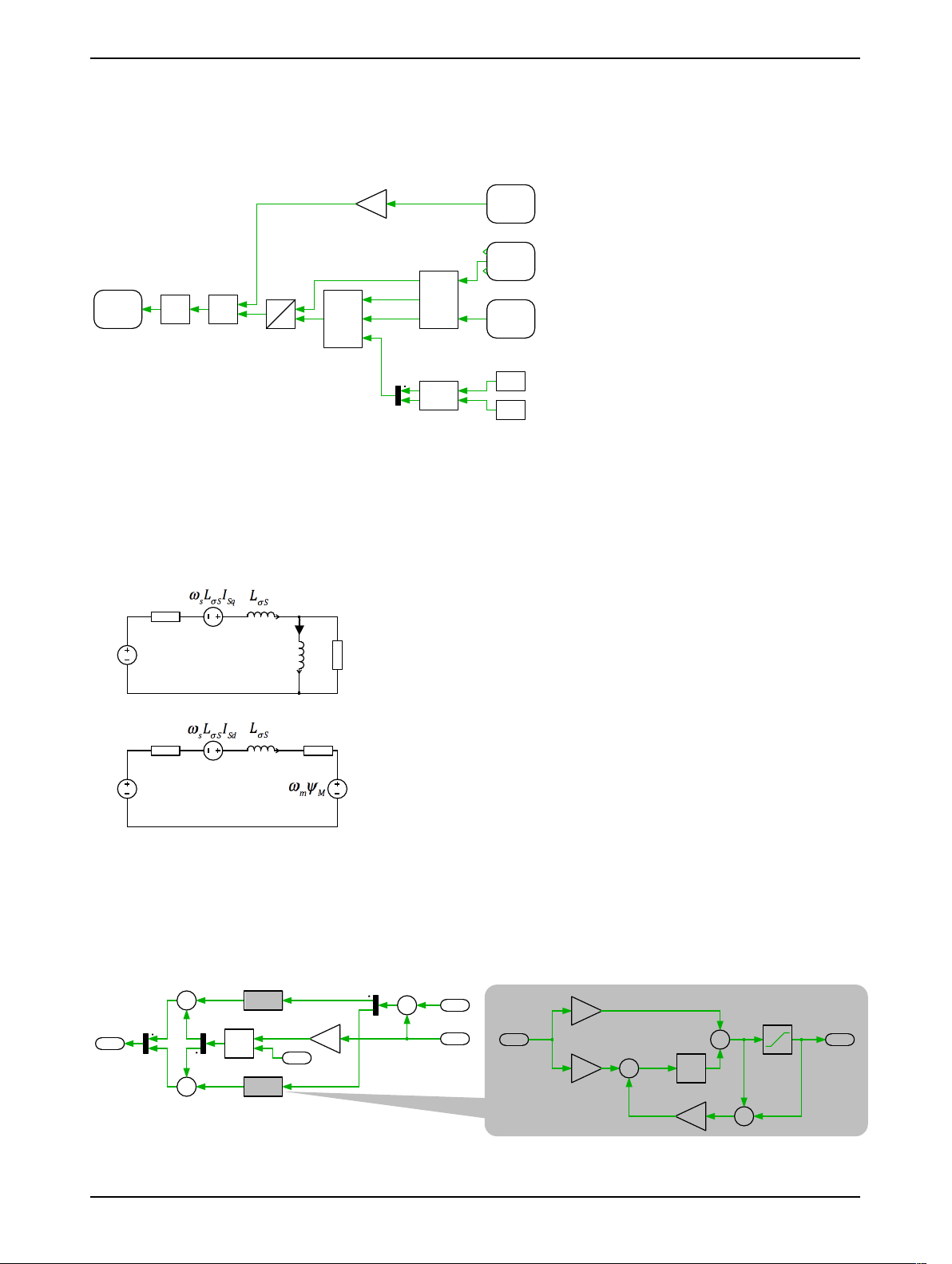
This demo model features an induction motor drive system with field oriented control. The drive is fed
by a DC voltage of 400 V and produces 200 Nm of torque. The model is split into two distinct subsys-
tems called “Plant” and “Controller”. The plant contains the drive system and the controller employs a
vector control scheme. These subsystems can then be independently built on the PLECS RT Box either
for Hardware-in-the-loop (HIL) testing of an external controller, or for rapid control prototyping (RCP).
The following sections provide a brief description of the model and instructions on how to simulate it.
Real-time execution on the RT Box requires the model to execute using a fixed-step solver. The dis-
cretization step size parameter specifies the base sample time of the generated code and is used to dis-
cretize the physical model and control domain state-space equations. The execution time represents
the actual time it takes to execute one discrete step of the PLECS model on the RT Box hardware. The
chosen discretization step sizes and average execution times for each subsystem in this demo model
are shown in Tab. 1.
Table 1: Discretization step size and average execution time of real-time models with two RT Box 1
Subsystem Discretization Step Size Average Execution Time
Plant 5 µs 2.4µs
Controller 100 µs(fsw = 10 kHz)2.8µs
1.1 Requirements
To run this demo model, the following items are needed (available at www.plexim.com):
• Two PLECS RT Boxes and one PLECS and PLECS Coder license
• The RT Box Target Support Library
• Follow the step-by-step instructions on configuring PLECS and the RT Box in the Quick Start guide
of the RT Box User Manual.
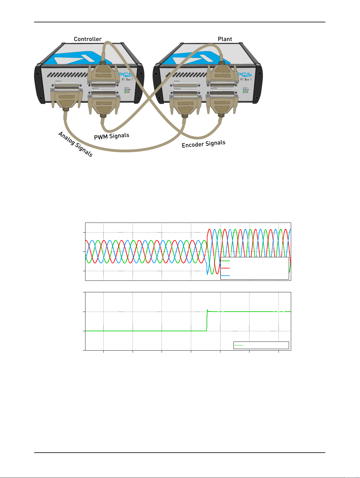
• Three 37 pin Sub-D cables to connect the boxes front-to-front.
Note that this demo model is targeted at two RT Boxes application, with one running the Plant and
the other running the Controller. In this way, the execution time of each real-time target is minimized.
Besides, the setup can easily transition to a HIL or RCP test later on.
However if the user has only one RT Box available, please check the corresponding models targeted
for one RT Box application. In this case, two 37 pin Sub-D cables are still needed to connect in front
Analog Out interface with Analog In interface, and Digital Out interface with Digital In interface.
• For RT Box 2 and 3, by default the multi-tasking feature is enabled in this demo. “Controller” part
is circled with a Task frame block, and runs in one core. The rest of the circuit on the schematic be-
longs to the “Base task”, and runs in another core. In this way the computational effort is split onto
different cores. Please check the default setting under Scheduling tab of the Coder options... win-
dow.
• For RT Box 1, multi-tasking is disabled since there is only one CPU core available for calculating
the model, which includes both Plant and the Controller.
Note This model contains model initialization commands that are accessible from:
PLECS Standalone: The menu Simulation + Simulation Parameters... + Initializations
PLECS Blockset: Right click in the Simulink model window + Model Properties + Callbacks +
InitFcn*
www.plexim.com 1

Vector Control of an Induction Machine
2 Model
The top level schematic contains two separate subsystems representing the controller and plant mod-
els, as shown in Fig. 1. Both subsystems are enabled for code generation from the Edit + Subsystem
+ Execution settings... menu. This step is necessary to generate the model code for the RT Box.
Controller
Vdc
Is
sw
θ/A,B,I
Plant
Is
sw
Vdc
θ/A,B,I
z-1
z-1
VectorControlofanInductionMachinedeployableontheRTBox
Figure 1: Top level schematic of the plant and the controller subsystems
2.1 Power Circuit
The power circuit includes an induction machine (IM) and a three-phase full bridge voltage source
inverter (VSI). The mechanical interface of the IM is loaded by a linear friction block via a gear box.
The DC voltage source Viwith Vdc = 400 V supplies the VSI, which is represented by three IGBT Half
Bridge power modules.
The six switching signals are brought into the subsystem by a PWM Capture block from the PLECS
RT Box component library. The measurements of the DC voltage and the AC current are exported out
of the subsystem by Analog Output ports. The rotor angular position and rotational speed are con-
verted by the Incremental Encoder block into digital orthogonal pulses, which can be measured outside
of the subsystem.
Vi
V
sw1
sw2
sw3
sw4
sw5
sw6
sw1
sw2
sw3
sw4
sw5
sw6
Is
Analog
Out
sw
PWM
Capture
Vdc
Analog
Out
θ
Incr.
Encoder
Probe
IM
Figure 2: Power circuit of the induction machine drive system
2.2 Controls
In the controller subsystem, the measurements of the DC-link voltage and the stator currents are im-
ported by Analog In blocks. The mechanical angular speed of the rotor is obtained from the Quadra-
www.plexim.com 2

Vector Control of an Induction Machine
ture Encoder Counter block, which converts the orthogonal digital pulses.
Rotor-field oriented control is applied to the drive system and the basic structure is shown in Fig. 3,
where the stator current is regulated in the dq frame.
U(I)
Vdc
Analog
In
Is
Analog
In
100
Te
PI
Idq*
Vs*
Idq
ωe
ψresti.
Is
θe
ωe
ωm
Idq
θ
c
ω
2
s
Enc.
Count
sw
PWM
Out
0.3
ψr*
Transform
|ψr*|
Te*
Iq*
Id*
*
/
0.5
dq
abc
Figure 3: Controller model of the induction machine drive system
Fig. 4 shows the equivalent circuit of the induction machine in the dq frame, which rotates syn-
chronously with the rotor flux. The values of LM,LσSand RRare calculated from the original machine
parameters, which can be found in the initialization commands of the model, (see Note above in Sec-
tion 1).
!
Vsd
!LM
!RR
!Rs
!Rs
!RR
!IMd
!
Vsq
Figure 4: Equivalent circuit of the induction machine in the dq frame
The PI controllers for the d and q axis currents are included in the subsystem “PI”, as shown in Fig. 5.
The proportional and integral gains are designed following the “Optimum Magnitude” method, which
is described in more detail in the “Boost Converter” demo model of the RT Box Target Support Pack-
age..
Idq*
Vs*
Idq
ωe
+
−
K
Lσ
+
−
+
+
*
*
d-axis
i
o
q-axis
i
o
i
o
K
Kp
K
Ki
1/s
+
+
+
−
K
+
−
Figure 5: PI controller in the dq frame
www.plexim.com 3

Vector Control of an Induction Machine
To avoid the use of an embedded flux sensor, a magnetic flux estimator introduced on page 322 of [1] is
employed in the subsystem “Ψresti.”. Making use of the measured mechanical angular speed ωm, the
stator current is transformed into the rotor reference frame (RRF) as ~
Is,xy. The rotor flux ~
dΨr,xy in the
RRF is governed by the differential equation below:
~
dΨr,xy
dt =RR(
−~
dΨr,xy
LM
) + ~
Is,xy (1)
Following the differential equation, ~
dΨr,xy can be calculated using ~
Is,xy as the input. Processing the “x”
and “y” components of the rotor flux in the RRF by a Rectangular to Polar transformation block, yields
the slip angular position. Summing up the slip angular position and the mechanical angular position,
one can obtain the electrical angular position θ.θis further used to transform the stator current from
the abc frame to the dq frame. The structure of the rotor flux estimator is demonstrated in Fig. 6.
Is
θe
ωe
ωm
Idq
RR
1/s
+
−
K
1/s
abc
dq
p
+
+
abc
dq
p
+
+
C-Script
θe->ωe
Figure 6: Structure of the rotor flux estimator
The current reference in the dq frame is converted from the torque and flux reference by the subsys-
tem “Transform”.
3 Simulation
This model can run both, in offline mode on a computer or in real-time mode on the PLECS RT Box.
For the real-time operation, two RT Boxes (referred to as “Plant” and “Controller”) need to be set up as
demonstrated in Fig. 7 using three DB37 cables.
Please follow the instructions below to run a real-time model on two RT Boxes:
• From the System tab of the Coder options... window, select the “Plant” and Build it onto the
“Plant” RT Box. Then, select “Controller" and Build it onto the “Controller” RT Box.
• Once the models are uploaded, from the External Mode tab of the Coder options... window, Con-
nect to both RT Boxes and Activate autotriggering.
The stator current, rotational speed and electrical torque are shown in the scope of the “Plant” subsys-
tem. In the XY plot Ψrthe rotor flux is displayed and it should be a circle in steady-state operation. To
observe a transient behavior of the system, e.g. a step change of the torque reference from 100 Nm to
200 Nm, please further follow the scenario below:
• Make sure that the External Mode and Activate autotriggering of both RT Boxes are enabled.
• Switch the Trigger channel parameter to [Electrical torque] in the External Mode tab of the
“Plant” subsystem’s Coder options... window.
• Setup the Trigger level parameter to be 150 and Trigger delay [steps] to be −50000.
www.plexim.com 4

Vector Control of an Induction Machine
Analog In
Analog Out
Digital In
Digital Out
Analog In
Analog Out
Digital In
Digital Out
Controller Plant
Analog Signals
PWM Signals
Encoder Signals
Figure 7: Hardware configuration for the real-time operation of the demo model
• Open the controller subsystem and change the Constant block “Te” from the default value of 100 to
200.
The step change will be captured by the scope in the “Plant” subsystem, as shown in Fig. 8.
StatorCurrents
ElectricalTorque(Te)
Current(A)
-200
0
200
Time(s)
1.15 1.20 1.25 1.30 1.35 1.40 1.45
Torque(Nm)
0
100
200
300
Current(3phMeter):1
Current(3phMeter):2
Current(3phMeter):3
Electricaltorque
Figure 8: Transient response of a step change of the torque reference in the controller
4 Conclusion
This model demonstrates an induction machine drive system which can run in both offline simulation
and real-time operation for Hardware-in-the-loop testing and rapid control prototyping.
www.plexim.com 5

Revision History:
RT Box Target Support Package 1.8.5 First release
RT Box Target Support Package 2.1.5 Turn on Assertions in IGBT Half
Bridges and add deadtime in the
PWM Out block
How to Contact Plexim:
+41 44 533 51 00 Phone%
+41 44 533 51 01 Fax
Plexim GmbH Mail)
Technoparkstrasse 1
8005 Zurich
Switzerland
http://www.plexim.com Web
RT Box Demo Model
© 2002–2021 by Plexim GmbH
The software PLECS described in this document is furnished under a license agreement. The software
may be used or copied only under the terms of the license agreement. No part of this manual may be
photocopied or reproduced in any form without prior written consent from Plexim GmbH.
PLECS is a registered trademark of Plexim GmbH. MATLAB, Simulink and Simulink Coder are regis-
tered trademarks of The MathWorks, Inc. Other product or brand names are trademarks or registered
trademarks of their respective holders.
Other manuals for PLECS RT Box
7
This manual suits for next models
3
Table of contents
Other Plexim Media Converter manuals

Plexim
Plexim PLECS RT Box User manual

Plexim
Plexim PLECS RT Box User manual

Plexim
Plexim PLECS RT Box User manual

Plexim
Plexim PLECS RT Box User manual

Plexim
Plexim PLECS RT Box User manual

Plexim
Plexim PLECS RT Box User manual

Plexim
Plexim PLECS RT Box User manual

Plexim
Plexim RT Box TSP 2.0.5 User manual