Plexim PLECS RT Box User manual

Dual Active Bridge Converter
1 Overview
This RT Box demo model features a dual active bridge (DAB) DC/DC converter for battery charg-
ing applications. The following sections describe in detail the implementation of the power stage and
controls using the PLECS Electrical and Control domains. This demo model has the following fea-
tures:
• The DAB delivers up to 50 kW from an 800 V DC input to a 200 V, 100 kWh battery pack. The DAB
power stage has been implemented using the DAB power module available in the PLECS library.
This allows us to use the “Sub-step events" implementation, which increases the calculation accu-
racy by performing sub-step calculations within one simulation step, which results in the calculation
of as many inductor current values as switching combinations encountered during one simulation
step. This is specially critical for topologies like the DAB.
• The closed-loop current controller is a PI regulator with a non-linear feedforward action based on
the DAB current-phase shift angle relation. The controller has been designed to achieve a 400 Hz
closed-loop current control bandwidth. The output of the PI regulator sets the phase shift of the
transformer primary and secondary PWM signals.
• DAB current oversampling and a Moving Average Filter (MAF) have been implemented for the
closed-loop current control. Oversampling and filtering are used since the PWM frequency is 40 kHz
and the controller is executed at 400 kHz.
• The plant and controller models are implemented in separate subsystems. This allows the same
model to be used in an offline simulation in PLECS and for real-time simulations on the RT Box. In
this demo, plant model is run on one RT Box and another RT Box used to simulate the digital con-
trol system in a virtual prototyping configuration. The two RT Boxes are connected for a complete
closed-loop simulation.
This document discusses both the plant model as well as the current control design, with a special fo-
cus on modelling the phase shift modulation technique and the technical solutions for implementing
oversampling.
Discretization step sizes are critical for converter simulations such as the DAB, where power/energy
transfer is provided at the switching frequency components. In order to obtain accurate simulation re-
sults, the discretization step needs to be significantly smaller than the switching period. In this partic-
ular model, the following discretization steps and execution times are achieved:
Table 1: Discretization step size and average execution time of real-time models with two RT Boxes
Subsystem Discretization Step Size Average Execution Time
Plant 2.5 µs 2.3µs
Controller 2.5 µs(fsw = 40 kHz)1µs
1.1 Requirements
To run this demo model, the following items are needed (available at www.plexim.com):
• Two PLECS RT Boxes and one PLECS and PLECS Coder license
• The RT Box Target Support Library
• Follow the step-by-step instructions on configuring PLECS and the RT Box in the Quick Start guide
of the RT Box User Manual.
• Two 37 pin Sub-D cables to connect the boxes front-to-front.
www.plexim.com 1

Dual Active Bridge Converter
Note This model contains model initialization commands that are accessible from:
PLECS Standalone: The menu Simulation + Simulation Parameters... + Initializations
PLECS Blockset: Right click in the Simulink model window + Model Properties + Callbacks +
InitFcn*
2 Model
The top level schematic of the demo model is depicted in Fig. 1. The model is split into two subsys-
tems: “DAB Plant” and “Controller”. Both subsystems are enabled for code generation by right-clicking
on the component and selecting Enable code generation check box from the Subsystem + Execu-
tion settings... menu. The “DAB Plant” subsystem will run on one RT Box and the “Controller” sub-
system will run on a second RT Box.
The inherit delays of the closed-loop control are modelled in the offline simulation. Therefore, a De-
lay block (z−1), with sample time equal to one Controller acquisition step (Tdisc.Acq), is added to the
offline simulation.
Controller
PWMOut
V_LV
V_HV
I_LV
DABPlant
V_LV
V_HV
PWMCapture
I_LV
z-1
DualactivebridgeconverterdeployableonPLECSRTBox
Figure 1: Top level schematic of the DAB plant and controller model
2.1 Plant Model
Fig. 2 shows the circuit model of the “DAB Plant”, which comprises a DAB connected to a 200 Vdc
battery pack on th low-voltage (LV) side and an 800 Vdc source on the high-voltage (HV) side. Tab. 2
shows the physical parameter used in this demo model.
Table 2: Parameters set
VLV,nom VHV,nom CLV ILV,nom Pnom Rlk Llk fsw EESS,nom
200 V 800 V 10 mF 250 A 50 kW 100 mΩ 1.75 µH 40 kHz 100 kWh
The plant model uses the following blocks from the RT Box Target Support Library to access the phys-
ical input and output ports of the RT Box:
• The PWM Capture block samples incoming switching signals every 7.5 ns. The sampled switching
signals are time-averaged over each model step for high-fidelity resolution of the PWM inputs. To
utilize the time-averaged PWM input in the simulation an “IGBT Full Bridge (Series Connected)"
power module is used with the “sub-cycle average” configuration selected [1].
www.plexim.com 2

Dual Active Bridge Converter
V
V_HV
V:
V_HV
S58
S67
S14
S23
V_LV
V
V_LV
V_HV
V_LV
channel:
0
Analog
Out
V_HV
channel:
1
Analog
Out
ESS
200V
100kWh
+
-
SoC
A
I_LV
[0000]
OLPWM
Enable
PWMCapture
PWMCapture
PWM
Capture
I_LV
I_LV
channel:
2
Analog
Out
DAB
Waveforms
V_LV
V_HV
1/n
S14
S58
S23
S67
Probe
S23
S14
S58
S67
S14
S23
S67
S58
DAB
L
n
:
1
Figure 2: Schematic of the DAB plant model
• Analog Out blocks provide the analog signals required by the controller subsystem such as battery
current, input voltage, and output voltage. The Analog Out component contains scale and offset pa-
rameters that are set to avoid saturating the analog outputs of the RT Box and to match IO require-
ments of connected hardware or controller. Appropriate scaling factors can be determined with an
offline simulation in PLECS. In the case of the grid-side voltage, the nominal voltage value is 800 V.
An extra 50% voltage margin is added in order to allow for voltage deviations and transients on the
voltage signals. The RT Box analog input voltage range for the controller is ±10 V, as specified by
the user in the Target tab of the Coder Options window. Therefore, the Analog Out parameters
were set as:
VHV,scale =VRange−AO/VHV,max = 20/1200,
VHV,offset =−VRange−AO/2 = −10 V,
VLV,scale =VRange−AO/VLV,max = 20/300,
VLV,offset =VRange−AO/2 = −10 V,
ILV,scale =VRange−AO/(ILV,max ·2) = 20/(750 ·2),
and,
ILV,offset = 0.
Note that in this virtual prototyping setup it does not matter which IO channels are configured, but
the channel IDs must match between the “Controller” and “DAB Plant” subsystems.
The battery pack model has been built based on the Panasonic UR18650A cell, which has the following
characteristics:
Table 3: Parameters set
Rated Capacity Nominal Voltage Charging: CC-CV, Std. 1505 mA, 4.20V
2250 mAh 3.6 V 3 h
The charge and discharge characteristic of the cell are shown in Fig. 3. A battery pack of 200 V,
50 kW, and 100 kWh, has been modelled with 239 parallel cell branches, with 56 cells in series in each
branch.
The DAB converter is formed by two full bridges (FBs) interconnected by a medium frequency trans-
former (MFT). The MFT has been modeled with an ideal transformer in series with a resistive-
www.plexim.com 3

Dual Active Bridge Converter
0 50 100
2
3
4
5
Time (minutes)
Voltage (V)
0
833
1666
2500
Current (A)
Voltage
Current
Capacity
0 500 1,000 1,500 2,000 2,500
2
3
4
5
Discharge Capacity (mAh)
Voltage (V)
0.2 C
1 C
2 C
3 C
Figure 3: Charging and discharging characteristics of a Panasonic UR18650A battery cell
inductive impedance representing the transformer winding resistance and leakage inductance, as
shown in Fig. 2.
There are several different approaches to control a DAB, however a common approach is to use phase
shift modulation. The DAB is operated with a constant duty cycle for both the HV and LV FBs and
the phase shift between the HV and LV PWM carriers is used to control the current. Fig. 4 shows the
typical waveforms of a DAB operated under phase shift modulation.
180
190
200
Voltage (V)
Battery-side Voltage (VLV )
DC Grid-side Voltage (VHV /n)
0
0.5
1
Φ
Tsw
PWM
S14
S58
0
0.5
1
PWM
S23
S67
−400
0
400
Voltage (V)
Leakage Inductance Voltage (VLK )
0 0.05 0.1 0.15 0.2
−400
0
400
Time (ms)
Current (A)
Inductor Current (ILK )
Rectified Current (ILV )
Figure 4: DAB voltage and current waveform during operation, in an RT Box 1, at 10 kHz and 1.25 µs
simulation step size.
www.plexim.com 4

Dual Active Bridge Converter
For an average carrier period, the current drawn from the low voltage terminal is given by:
hILV(Φ, VHV, t)iTc≡VHV ·(π−Φ) ·Φ
2·π2·L·fsw ·n∀0≤Φ≤π. (1)
where VHV is the voltage at the HV DAB terminal, fsw is the switching frequency, Lis the leakage in-
ductance of the MFT, nis the MFT’s turn ratio, Tc= 1/fsw is the carrier period, and Φis the relative
phase-shift angle between the PWMs applied to the switches of the LV and HV FBs.
For Φ = 0 the output is zero, then current increases non-linearly with Φ, until a maximum is reached
for Φ = π/2. If the phase shift angle is further increased, the output decreases until it reaches zero at
Φ = π. Fig. 5 shows the expression of the battery-side current (ILV) as function of the phase shift angle
(Φ). By analyzing Eq. (1), it can be seen that, the battery current (ILV) is not dependent on VLV.
−π/2−π/40π/4π/2
-375
−Inom -250
-125
0
125
Inom 250
375
Phaseshift Angle Φ(rad)
Current (A)
Non-linear Φ −ILV curve
Linear Approximation ILV =KDABI·Φ
Nominal Current
Figure 5: Non-linear ILV expression as function of the phase shift angle Φ
2.2 Controller
Fig. 6 shows the PLECS schematic with the controller implementation. The main controller features
are summarized as follows:
• Oversampling implementation of input signal ILV.
• Calculation of averaged ILV per switching cycle.
• Look-up table based feedforward + PI current regulator.
• 400 Hz designed control bandwidth for PI tuning.
The “Controller” subsystem contains the following components from the RT Box Target Support Li-
brary:
•Analog In blocks provide the analog signals from the “DAB Plant” subsystem. The input signals can
be scaled and offset, similar to the Analog Out block. In this model, the Analog In scaling factors
are set to the inverse of the Analog Out scaling factors. The current and voltage values in the “Con-
trol” subsystem will then correspond to unscaled voltage and current measurements in the power
stage.
• The PWM Out block is used to generate the appropriate PWM signals at the digital out connector.
In this model duty cycle and frequency modulations are not used, therefore all PWM signal are
given a constant duty cycle value of 0.5, and frequency of 40 kHz. The intention of the phase shift
angle command (Φ∗) is described below.
www.plexim.com 5

Dual Active Bridge Converter
PWMOut
m
fc'
ph'
PWM
Out
[0.50.50.50.5]
DutyCycle
[1]
fnominal
Downsampling
In1
Out1
V_LV
channel:
0
Analog
In
V_HV
channel:
1
Analog
In
trig_samp
Vlv_f
Vhv_f
Vhv_f
+
+
Phi_total
Ilv*
Plv_f
*
*
Primary
Control
Vlv_samp
Vhv_samp
nnzn+..+n0
dnzn+..+d0
FFDiscrete
LPF
Ilv_f
Ilv*
Ilv_f
Phi_FF
Phi_PI
Phi_FF
Phi_PI
Phi_total
Closed\Open-loop
Enable
pi/4
OLPhi
2D
Table
x
y
I_LV-PhiLUT
Plv_f
1
EnableFF
I_LV
channel:
2
Analog
In
Ilv_samp
Ilv_f
Vlv_samp
Vhv_samp
Ilv_samp
PhaseShiftGenerator
PhaseShift
Angleinrad
PhaseShiftAngles
4PWMinp.u.
SamplingTrigger
Ilv_samp_MAF
Measurements
Vlv_samp
Vhv_samp
Ilv_samp
Ilv_samp_MAF
nnzn+..+n0
dnzn+..+d0
DiscreteMAF
trig_samp
-1
Ilv_f
PIController
Output
Input
Reference
1/n
Vlv_samp
Vhv_samp
Reference
Generator
Out
Figure 6: Schematic of the controller model
Oversampling implementation and Filtering
In order to avoid the introduction of high-order/complex physical filters in the DAB plant, the switch-
ing DC current at the FB input, before the filter capacitor, has been used as feedback for the control.
This approach requires the use of oversampling methods in order to accurately calculate the average
converter current over a switching period. This implementation allows for a faster execution of the
converter model at the expense of a more complex controller structure.
ILV is sampled 10 times per switching cycle, every 2.5 µs (Tdisc.Acq), for a 40 kHz switching frequency
(fsw). A MAF is used to obtain the average ILV during the switching period. The averaged ILV current
is sampled once per switching cycle, synchronizing with the control execution time step.
The MAF is implemented with a discrete transfer function, given by:
ILV(z)
ILV(z)=1
N·1−z−N
1−z−1,(2)
where Nis the number of samples for every switching period. The output of the MAF is then given
once every 25 µs (Tdisc.Control), in order to synchronize the DAB current measurement with the control
execution.
0 5 10 15 20 25 30 35
−400
−200
0
200
400
Tdisc.Acq Tdisc.Control
Time (µs)
Current (A)
Rectified Current (ILV )
Samples (ILV )
Sampled MAF Output
Figure 7: Oversampling and averaging of ILV current
www.plexim.com 6

Dual Active Bridge Converter
PWM generation
The control calculates the phase shift angle that needs to be applied to the FBs to regulate the cur-
rent. A PWM Out (Variable) block from the RT Box Target Support Library is used, since it allows the
phase shift between the PWM carriers to be dynamically adjusted. The block accepts carrier phase
shift values for each PWM channel from 0 to 1 in p.u. (i.e. 0 means 0◦phase shift and 1 means 360◦
phase shift). The first channel defined in the PWM block acts as master, therefore, the phase shift
specified for the rest of the channels sets the phase shift with respect to the master channel. It is im-
portant to remark that the block does not accept negative phase shift values.
In order to adapt the phase shift angle from radians to p.u. and account for negative values, the fol-
lowing implementation is provided in this demo model:
Φp.u.= sign(Φrad) + 1
2π·Φrad sign(Φrad) =
0,if Φrad ≥0
1,if Φrad <0
(3)
For the DAB implementation four different PWM signals need to be generated, two for each FB. The
two PWM signals for the same FB are phase-shifted 180◦. An additional phase shift is applied to the
PWM signals of the HV FB with respect the PWM signals of the LV FB. In total 4 phase shift angles
need to be provided.
For implementations where the sampling and switching periods are equal, the phase shift provided
for the first (master) PWM channel is commonly set to zero. However, with oversampling, the first
PWM has to be shifted. The reason for this is the following: the counters configured with the “PWM
Out (Variable)” block, are restarted every time the blocks are executed, every Tdisc.Acq in this particu-
lar case. Since Tdisc.Acq is significantly smaller than the switching period, Tdisc.Control, the PWM output
signal are not generated properly. In order to account for this behavior, the master PWM is shifted. A
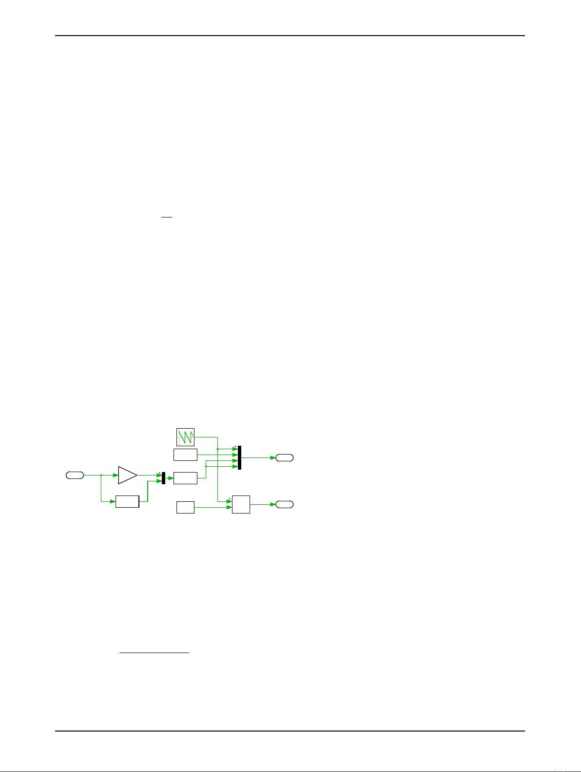
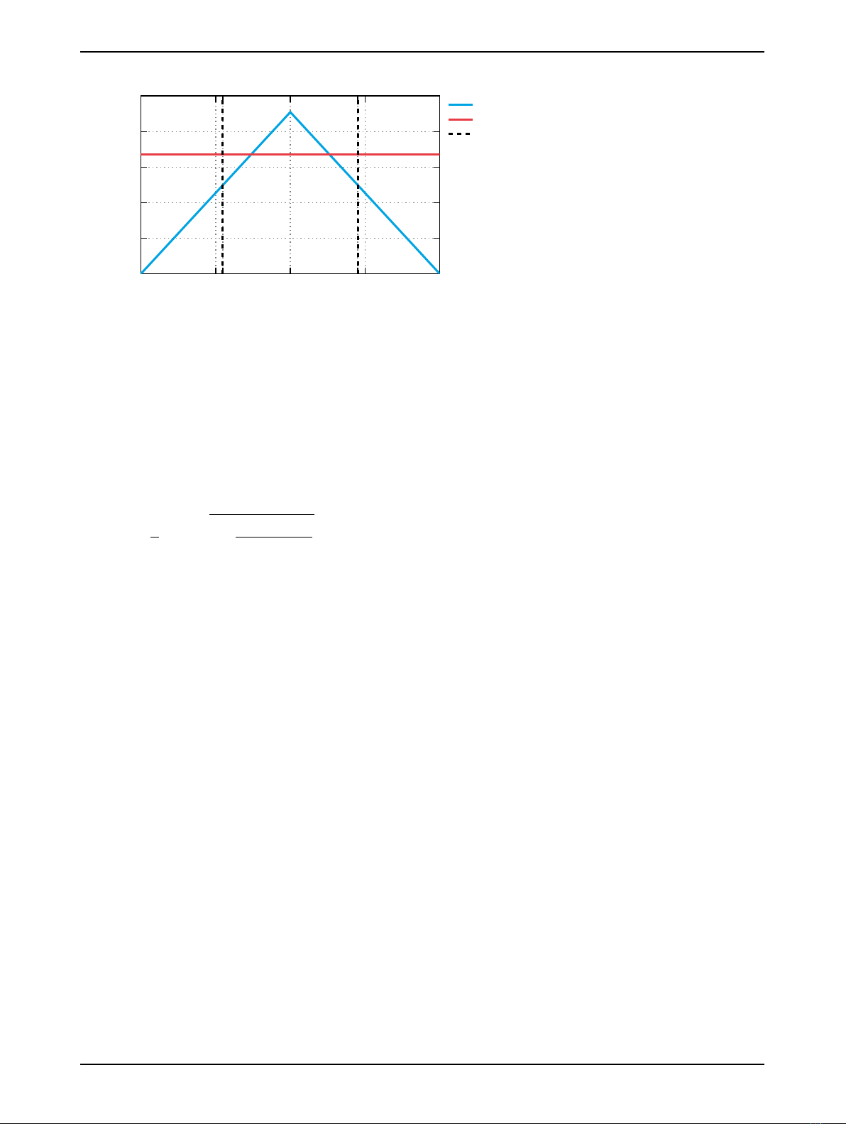
simple Triangular Wave Generator is used with Minimum signal value 0, Maximum signal value 1,
Frequency fsw,duty cycle 0, and Phase delay 0. This generates a ramp, which is 1 at the switching
instant and reaches 0 at the next switching instant.
Fig. 8 shows the “phase shift generator” implementation.
PhaseShift
Angleinrad
PhaseShiftAngles
4PWMinp.u.
[0]
DelayFBLV
>=
0.5
SamplingLevel
0.5=Midcycle
K
rads->p.u.
<0
f(u)
adjustfor
negativePhi
SamplingTrigger
Figure 8: Schematic of the phase shift generator subsystem
Plant Linearization
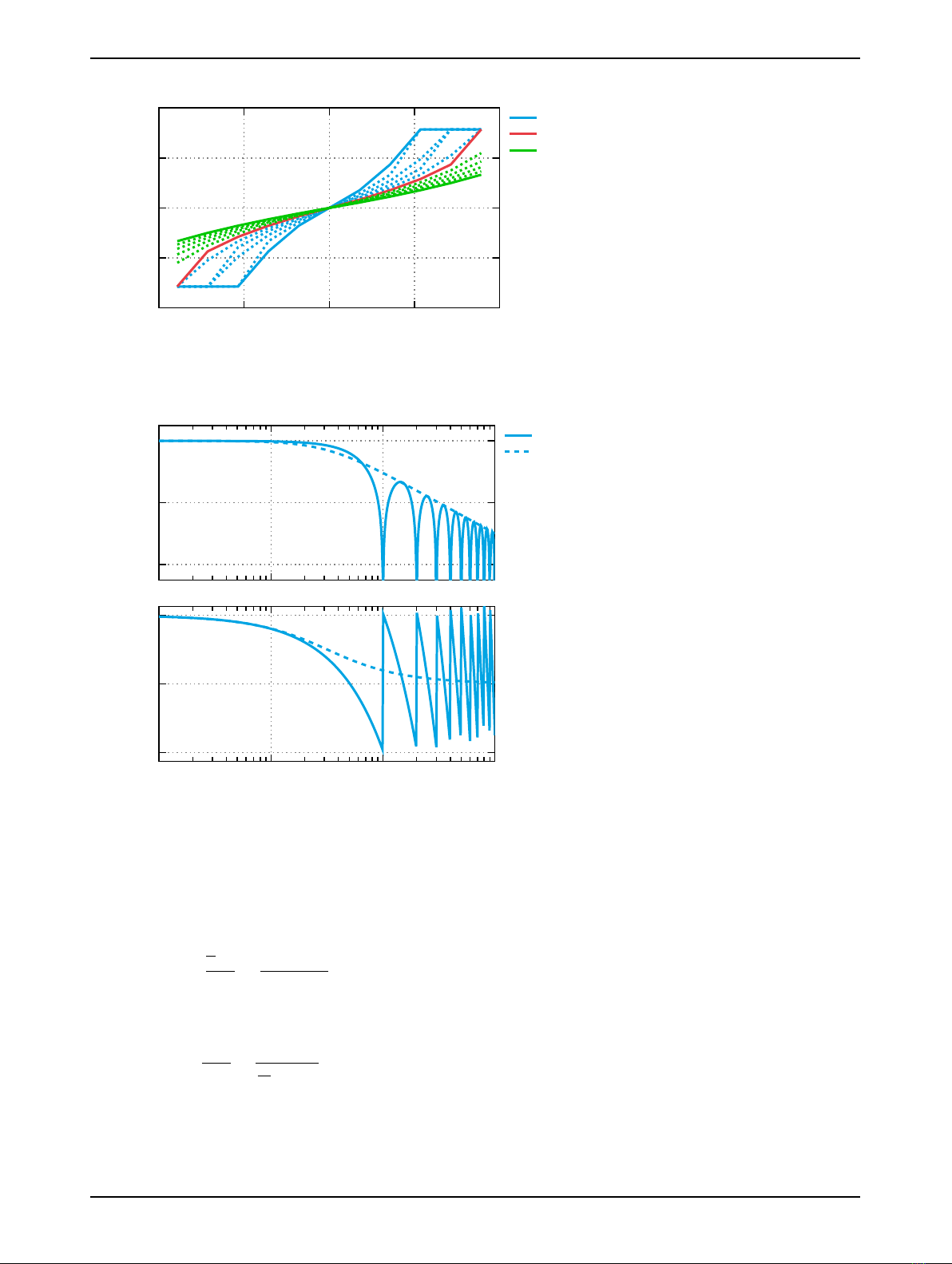
As shown in Fig. 5, the Φ−ILV expression has been linearized for the controller design. The small
signal expression, derived from Eq. (1), between the perturbation of current (∆ILV) and phase shift
angle (∆Φ) is given by:
∆ILV(t) = VHV
2·π2·L·fsw ·n·(π−2·Φ) ·∆Φ(t) = KDABI·∆Φ(t)∀0≤Φ≤π. (4)
Fig. 9 shows the KDABIvalues for different operating points, where KDABIis the current gain as a lin-
ear function of phase angle. For the PI regulator tuning purposes it has been found that the use of a
linear approximation of KDABIis sufficiently accurate to model the closed-loop dynamics of the system
with relatively low closed-loop control bandwidths [2].
www.plexim.com 7

Dual Active Bridge Converter
−π/2−π/4−Φnom 0Φnom π/4π/2
0
100
200
300
400
500
Phaseshift Angle Φ(rad)
KDABI
Non-linear Φ −ILV curve
Linearized KDABI
Nominal Φ
Figure 9: KDABIvalues for different phase shift angles
Feedforward controller
Frequency modulated or phase shift modulated power converters are well suited for controllers with
feedforward control. In this particular example, the relation between the battery current (ILV) and the
control action (Φ) is given in Eq. (1). The required control action can be pre-computed for different op-
erating conditions (e.g. different values of VHV). The expression to calculate the control action is the
following:
ΦFF =π
2"1−s1−8·fsw · |I∗
LV|
VHV/n #·sign(I∗
LV)∀ |I∗
LV| ≤ |ILV,MAX |(5)
with,
sign(I∗
LV) =
1, if I∗
LV ≥0
−1, if I∗
LV <0
.(6)
The feedforward control action provides a good approximation of the required phase shift angle to pro-
vide the required battery current. The PI regulator resolves the difference between estimated phase
shift from the feedforward function and the measured variable ILV. The differences between the cal-
culated and measured values originate from parameter variations (e.g. Lvariation with temperature),
unaccounted losses in the DAB model, and interpolation approximations between two pre-computed
feedforward values. In this demo model a look-up table has been used to implement the ΦFF pre-
computed values, as a function of ILV and VHV.
Measured signals used in the feedforward control path are filtered using a discrete Low Pass Filter
(LPF) in order to avoid instability problems due to high frequency disturbances.
PI controller tuning
The tuning methodology shown in [2] has been used to tune the PI regulator in this work. In order to
derive the closed-loop transfer function, MAF is approximated as a simple LPF. A comparison of the
frequency responses of both LPF and MAF are shown in Fig. 11.
www.plexim.com 8

Dual Active Bridge Converter
−400 −200 0 200 400
−2
−1
0
1
2
Current (A)
Phaseshift Angle Φ(rad)
VHV = 400V
VHV = 800V
VHV = 1200V
Figure 10: Data points for feedforward look-up table
−40
−20
0
Magnitude (dB)
MAF
LPF
fsw/100 fsw/10 fsw 10 ·fsw
0
−π/2
−π
Frequency (Hz)
Phase (rad)
Figure 11: Frequency response of implemented Moving Average Filter and Low Pass Filter approxima-
tion
The expression of the LPF is obtained from a first-order Padé approximation of the MAF expression in
the s-domain. Both expressions are as follows:
GMAF (s) = x(s)
x(s)=1−e−Ts·s
Ts·s(7)
and
GLP F (s) = y(s)
x(s)=1
Ts
2·s+ 1,(8)
where Tsis the MAF window length, which in this model is equal to the switching period.
Once the MAF approximation has been obtained, the open-loop transfer function is shown in Eq. (9).
It is important to remark that the feedforward control path has not been taken into account for the PI
www.plexim.com 9

Dual Active Bridge Converter
regulator tuning procedure.
ILV(s)=[I∗
LV(s)−ILV(s)] ·P I(s)·KDABI·GLPF(s).(9)
Re-arranging the PI regulator transfer function (P I(s) = kp+ki/s), and using the ωLP F = 2/Tsas the
LPF cut-off frequency, the open-loop transfer function is as follows:
ILV(s)=[I∗
LV(s)−ILV(s)] = kp·s+ki/kp
s·KDABI·ωLPF
s+ωLPF
.(10)
A zero-pole cancellation technique is employed by selecting kp/ki=ωLP F , and the closed-loop transfer
function is calculated:
ILV(s)
I∗
LV(s)=kp·KDABI·ωLPF
s+kp·KDABI·ωLPF
.(11)
The zero-pole cancellation simplifies the system to a first-order transfer function. In this scenario, kp
can be selected to achieve the desired current control closed-loop bandwidth, ωCL. The selection of the
PI regulator gains are calculated with the following expressions:
kp=ωCL
KDABI·ωLPF
(12)
and
ki=kp·ωLPF.(13)
3 Simulation
This model can run both, in offline mode on a computer or in real-time mode on the PLECS RT Box.
For the real-time operation, two RT Boxes (referred to as “Plant” and “Controller”) need to be set up as
demonstrated in Fig. 12. The figure shows a RT Box 1 in the setup but other versions of the RT Box
are also possible.
Analog In
Analog Out
Digital In
Digital Out
Analog In
Analog Out
Digital In
Digital Out
Controller Plant
Analog Signals
PWM Signals
Figure 12: Hardware configuration for the real-time operation of the demo model (example), runs
with all versions of the RT Box
Please follow the instructions below to run a real-time model on two RT Boxes:
www.plexim.com 10

Dual Active Bridge Converter
• Connect the Analog Out interface of the “Plant” RT Box to the Analog In interface of the “Con-
troller” RT Box, and the Digital In interface of the “Plant” RT Box to the Digital Out interface of
the “Controller” RT Box (e.g. using two DB37 cables shown in Fig. 12).
• From the System tab of the Coder options... window, select the “DAB Plant” and Build it onto
the “Plant” RT Box. Then, select “Controller" and Build it onto the “Controller” RT Box.
• Once the models are uploaded, from the External Mode tab of the Coder options... window, Con-
nect to the “Controller” RT Box and Activate autrotriggering.
Now, the DAB current reference is toggled between two values, which may be changed between a
maximum (250 A) and minimum (−250 A) value, depending on whether the battery is intended to be
charged or discharged, by modifying the value of the “ILrefmax” and “ILrefmin” blocks within the “Refer-
ence Generator” block of the “Controller” subsystem. The step responses of the closed-loop current con-
trol loop are shown in Fig. 13. It can be seen that the controller tracks the current with the designed
400 Hz bandwidth, when the feed forward action is disabled. The feed forward controller allows for a
faster reference tracking.
4 Conclusion
This RT Box demo model demonstrates a dual active bridge DC/DC converter with closed-loop current
control, based on phase shift modulation, for battery charging applications. The demo model can run
as an offline simulation or in real-time for hardware-in-the-loop or rapid control prototyping testing.
The “Controller” subsystem runs with a discretization step size of 2.5 µs, which is 10 times smaller
than the switching period, allowing for the implementation of an oversampling technique for pulsating
currents. The “DAB Plant” subsystem runs with a discretization step size of 2.5 µs. The actual execu-
tion time on a RT Box 1 is 1.1 µs for the controller, while the plant model runs in 2.3 µs.
References
[1] J. Allmeling, and N. Felderer, “Sub-cycle average models with integrated diodes for real-time simu-
lation of power converters,” IEEE Southern Power Electronics Conference (SPEC), 2017.
[2] F. D. Freijedo, E. Rodriguez, and D. Dujic, “Stable and Passive High-Power Dual Active Bridge
Converters Interfacing MVDC Grids,” IEEE Trans. Ind. Electron., vol. 65, no. 12, pp. 9561-9570,
Dec. 2018.
www.plexim.com 11

Dual Active Bridge Converter
Current Reference Tracking Performance
Phase Shift Angle Calculation
DAB Terminal Voltages
Current (A)
-300
-200
-100
0
100
200
300
Angle (rad)
-1.0
-0.5
0.0
0.5
1.0
× 1e-2
Time (s)
0.0 0.2 0.4 0.6 0.8 1.0 1.2 1.4
Voltage (V)
198
200
202
204
206
I_LV : FF OFF
I_LV* : FF OFF
I_LV : FF ON
I_LV* : FF ON
Phi FF : FF OFF
Phi PI : FF OFF
Phi FF : FF ON
Phi PI : FF ON
V_LV : FF OFF
V_HV/n : FF OFF
V_LV : FF ON
V_HV/n : FF ON
Figure 13: Reference current step test with feedforward enabled/disabled.
www.plexim.com 12

Revision History:
RT Box Target Support Package 1.8.3 First release
RT Box Target Support Package 2.0.5 Add new sub-step event power mod-
ule to plant, update documentation
How to Contact Plexim:
+41 44 533 51 00 Phone%
+41 44 533 51 01 Fax
Plexim GmbH Mail)
Technoparkstrasse 1
8005 Zurich
Switzerland
http://www.plexim.com Web
RT Box Demo Model
© 2002–2021 by Plexim GmbH
The software PLECS described in this document is furnished under a license agreement. The software
may be used or copied only under the terms of the license agreement. No part of this manual may be
photocopied or reproduced in any form without prior written consent from Plexim GmbH.
PLECS is a registered trademark of Plexim GmbH. MATLAB, Simulink and Simulink Coder are regis-
tered trademarks of The MathWorks, Inc. Other product or brand names are trademarks or registered
trademarks of their respective holders.
Other manuals for PLECS RT Box
7
This manual suits for next models
3
Table of contents
Other Plexim Media Converter manuals

Plexim
Plexim RT Box TSP 2.0.5 User manual

Plexim
Plexim PLECS RT Box User manual

Plexim
Plexim PLECS RT Box User manual

Plexim
Plexim PLECS RT Box User manual

Plexim
Plexim PLECS RT Box User manual

Plexim
Plexim PLECS RT Box User manual

Plexim
Plexim PLECS RT Box User manual

Plexim
Plexim PLECS RT Box User manual