Plexim PLECS RT Box User manual

Single-Phase Inverter
1 Overview
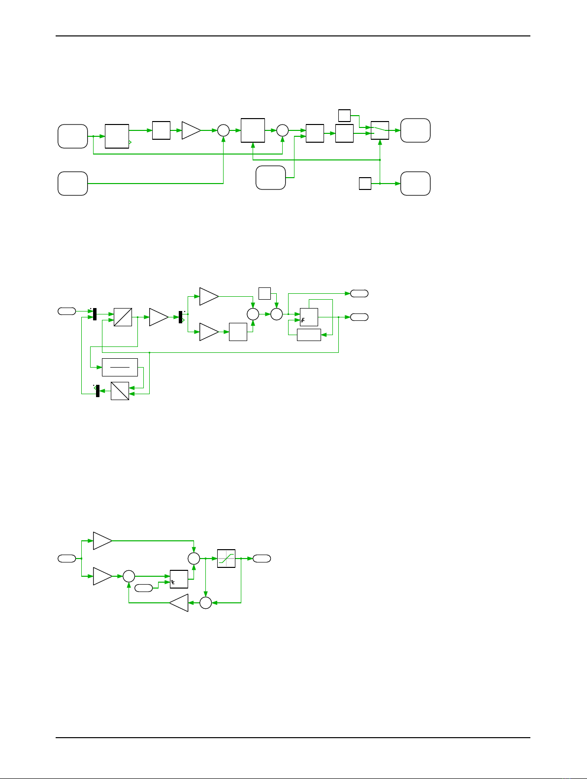
This demo model features a single-phase grid-connected inverter operating at 50 kW and unity power
factor. This document describes the implementation of the power stage and controls using the PLECS
electrical and control domains.
The plant and the controller models are split into two distinct subsystems. The subsystem represent-
ing the plant is deployed on one RT Box and the subsystem representing the controller is deployed on
a second RT Box. The two RT Boxes are connected front-to-front in a virtual prototyping configuration
with two 37 pin Sub-D cables to exchange digital PWM signals and analog current measurements. Vir-
tual prototyping is a potential first step when developing real-time models for Hardware-in-the-loop
(HIL) or rapid control prototyping (RCP) applications.
The chosen discretization step sizes and average execution times for each subsystem in the single-
phase inverter model are shown in Tab. 1. Real-time execution on the RT Box requires the model to
execute using a fixed-step solver. The discretization step size parameter specifies the base sample
time of the generated code and is used to discretize the physical model and control domain state-space
equations. The execution time represents the actual time it takes to execute one discrete step of the
PLECS model on the RT Box hardware. The processor loading is the ratio of the execution time to the
discretization step size.
Table 1: Discretization step size and average execution time of real-time models with two RT Box 1
Subsystem Discretization Step Size Average Execution Time
Plant 2 µs1.05 µs
Controller 62.5 µs(fsw = 16 kHz) 1.1 µs
1.1 Requirements
To run this demo model, the following items are needed (available at www.plexim.com):
• Two PLECS RT Boxes and one PLECS and PLECS Coder license
• The RT Box Target Support Library
• Follow the step-by-step instructions on configuring PLECS and the RT Box in the Quick Start guide
of the RT Box User Manual.
• Two 37 pin Sub-D cables to connect the boxes front-to-front.
Note that this demo model is targeted at two RT Boxes application, with one running the Plant and
the other running the Controller. In this way, the execution time of each real-time target is minimized.
Besides, the setup can easily transition to a HIL or RCP test later on.
However if the user has only one RT Box available, please check the corresponding models targeted
for one RT Box application. In this case, two 37 pin Sub-D cables are still needed to connect in front
Analog Out interface with Analog In interface, and Digital Out interface with Digital In interface.
• For RT Box 2 and 3, by default the multi-tasking feature is enabled in this demo. “Controller” part
is circled with a Task frame block, and runs in one core. The rest of the circuit on the schematic be-
longs to the “Base task”, and runs in another core. In this way the computational effort is split onto
different cores. Please check the default setting under Scheduling tab of the Coder options... win-
dow.
• For RT Box 1, multi-tasking is disabled since there is only one CPU core available for calculating
the model, which includes both Plant and the Controller.
www.plexim.com 1

Single-Phase Inverter
Note This model contains model initialization commands that are accessible from:
PLECS Standalone: The menu Simulation + Simulation Parameters... + Initializations
PLECS Blockset: Right click in the Simulink model window + Model Properties + Callbacks +
InitFcn*
2 Model
The top level schematic contains two separate subsystems representing the plant (“Plant”) and con-
troller (“Controller”) models, as shown in Fig. 1. Both subsystems are enabled for code generation from
the Edit + Subsystem + Execution settings... menu. This step is necessary to generate the model
code for the RT Box. Additional delays in the feedback path are also modeled.
Plant
sw
Vg
Ig
Vdc
CB
Controller
sw
Vg
Ig
Vdc
CB
z-1
Figure 1: Top level schematic of the controller and plant model
2.1 Power Circuit
The power circuit is supplied by a DC voltage source with Vdc = 750 V. The H-bridge is composed of
two IGBT Half Bridge power module components. The switching signals Q1, Q2, Q3and Q4are cap-
tured by the PWM Capture block from the PLECS RT Box Target Support library. The modeling of the
power module components and the sub-cycle averaged handling are described in the work of [2]. The
output of the H-bridge is connected to the power grid via a filter inductor and a circuit breaker. The
low voltage power grid is modeled by an ideal AC voltage source with Vrms = 220 V and f= 50 Hz. The
measurements of DC voltage, grid voltage and grid current are routed out of the subsystem via Analog
Out components from the PLECS RT Box Target Support library. The scaling factors and offsets are
configured to limit the analog output voltages within the range [−4 V,+4 V].
Vin
Lf1
Grid
Q1
Q2
Q3
Q4
sw
PWM
Capture
Q1
Q2
Q3
Q4
V
Vg
Analog
Out
Ig
Analog
Out
A
Rf1
Vdc
Analog
Out
V
CB
Digital
In
Figure 2: Power circuit of the single phase grid-connected inverter
www.plexim.com 2

Single-Phase Inverter
2.2 Controls
The closed-loop controller regulates the line current to be in phase with the grid voltage. A phase-
sw
PWM
Out
PLL
V
θ
ω
Vg
Analog
In
PICtrl
i
o
rst
Ig
Analog
In
sin
K
Ip
+
−
+
+
U(I)
Vdc
Analog
In
*
/
CB
Digital
Out
1
Breaker
C
Figure 3: Controller model of the single-phase grid-connected inverter
locked loop (PLL) based on the quadrature signal generator is included to detect the electrical angle
and frequency of the power grid. More details about this PLL structure have been introduced in [1].
The phase angle output of the PLL is converted into the reference signal of the grid current via one
V
θ
ω
αβ
dq
K
Kpd
Kp
Kp
Ki
Ki
1/s
+
+
+
+
C
ωn
1/s
>=C
αβ
dq
wf
s+wf
Figure 4: Phase-locked loop based on quadrature generator
Trigonometric Function block and a proportional gain Ip.Ipindicates the amplitude of the desired grid
current. The internal structure of the subsystem “Controller” can be switched between a proportional-
integral (PI) or proportional-resonant (PR) regulator. The parameters Kpand Kiof both types of reg-
ulators are set using the Optimum Magnitude rule. More details about the parameter calculation are
included in the description of the “Boost Converter” demo model of the RT Box Target Support Pack-
age. The resonant frequency ω0is selected to be equal to the grid frequency. Moreover, both regulators
are equipped with anti-windup logic, and the gain Kbc is determined by Kbc =Ki/Kp.
i
o
K
Kp
K
Ki
1/s
+
+
+
−
K
+
−
rst
Figure 5: Schematic of the PI regulator
At the output of the regulator, a feedforward of the grid voltage is added to improve the transient re-
sponse. After that, the signal is divided by the DC voltage and fed to the PWM Out block as a modula-
tion index. The PWM Out block has been configured to be synchronized with the execution step size of
the controller, if this model is programmed into the real-time target.
www.plexim.com 3

Single-Phase Inverter
i
o
K
Kp
K
Ki
1/s
+
+
1/s
+
−
K
w0^2
+
−
K
+
−
rst
Figure 6: Schematic of the PR regulator
3 Simulation
This model can run both, in offline mode on a computer or in real-time mode on the PLECS RT Box.
For the real-time operation, two RT Boxes (referred to as “Plant” and “Controller”) need to be set up
as demonstrated in Fig. 7. Please follow the instructions below to run a real-time model on two RT
Boxes:
• Connect the Analog Out interface of the “Plant” RT Box to the Analog In interface of the “Con-
troller” RT Box, and the Digital In interface of the “Plant” RT Box to the Digital Out interface of
the “Controller” RT Box (e.g. using two DB37 cables shown in Fig. 7).
• From the System tab of the Coder options... window, select the “Plant” and Build it onto the
“Plant” RT Box. Then, select “Controller" and Build it onto the “Controller” RT Box.
• Once the models are uploaded, from the External Mode tab of the Coder options... window, Con-
nect to both RT Boxes and Activate autotriggering.
• Change the value of the “Breaker” constant in the “Controller” subsystem to 1in order to engage
the breaker connecting the inverter and the power grid.
Analog In
Analog Out
Digital In
Digital Out
Analog In
Analog Out
Digital In
Digital Out
Controller Plant
Analog Signals
PWM Signals
Figure 7: Hardware configuration for the real-time operation of the demo model
During the real-time operation under External Mode the measurements and intermediate signals
on the controller box can be observed using in the PLECS Scope “Elec”. The grid phase angle, angu-
lar frequency detected by the PLL, and measured grid voltage and current are shown in Fig. 8. In
the plot at the bottom, the reference current and the measured current are compared with each other.
With a PR regulator, slightly less lag of the measured current can be observed, in comparison to that
with a PI regulator. The reference amplitude of the grid current can be changed by varying the gain
www.plexim.com 4

Single-Phase Inverter
Gridangle[rad/s]
Gridanglefrequency[rad/s]
Gridvoltage[V]
Gridcurrent[A]
0
2
4
6
250
300
350
400
-400
-200
0
200
400
0.00 0.01 0.02 0.03 0.04 0.05
-10
0
10
Gridangle[rad/s]
Gridanglefrequency[rad/s]
Gridvoltage[V]
Gridcurrent[A]
0
2
4
6
250
300
350
400
-400
-200
0
200
400
0.00 0.01 0.02 0.03 0.04 0.05
-10
0
10
ref
mes
With PI regulator With PR regulator
ref
mes
Figure 8: Real time measurements and intermediate signals obtained with PI and PR regulator on the
RT Box “Controller”
block “Ip” in the “Controller” subsystem. The inverter can be disconnected from the grid by setting the
“Breaker” constant inside the controller subsystem back to 0.
4 Conclusion
This model demonstrates a single-phase grid-connected inverter model which can run in both offline
simulation and real-time operation for Hardware-in-the-loop testing and rapid control prototyping.
References
[1] R. Teodorescu, M. Liserre and P. Rodriguez, “Grid converters for photovoltaic and wind power sys-
tems”, IEEE, Wiley, 2011
[2] J. Allmeling and N. Felderer, “Sub-cycle average models with integrated diodes for real-time simu-
lation of power converters,” 2017, 10.1109/SPEC.2017.8333566
www.plexim.com 5

Revision History:
RT Box Target Support Package 1.8.3 First release
RT Box Target Support Package 2.1.5 Turn on Assertions in the IGBT
Full Bridge and add deadtime in
the PWM Out block
How to Contact Plexim:
+41 44 533 51 00 Phone%
+41 44 533 51 01 Fax
Plexim GmbH Mail)
Technoparkstrasse 1
8005 Zurich
Switzerland
http://www.plexim.com Web
RT Box Demo Model
© 2002–2021 by Plexim GmbH
The software PLECS described in this document is furnished under a license agreement. The software
may be used or copied only under the terms of the license agreement. No part of this manual may be
photocopied or reproduced in any form without prior written consent from Plexim GmbH.
PLECS is a registered trademark of Plexim GmbH. MATLAB, Simulink and Simulink Coder are regis-
tered trademarks of The MathWorks, Inc. Other product or brand names are trademarks or registered
trademarks of their respective holders.
Other manuals for PLECS RT Box
7
This manual suits for next models
3
Table of contents
Other Plexim Media Converter manuals

Plexim
Plexim PLECS RT Box User manual

Plexim
Plexim RT Box TSP 2.0.5 User manual

Plexim
Plexim PLECS RT Box User manual

Plexim
Plexim PLECS RT Box User manual

Plexim
Plexim PLECS RT Box User manual

Plexim
Plexim PLECS RT Box User manual

Plexim
Plexim PLECS RT Box User manual

Plexim
Plexim PLECS RT Box User manual