Plexim RT Box TSP 2.0.5 User manual

dx
www.plexim.com
Request a PLECS and PLECS Coder trial license
Get the latest RT Box Target Support Package
Check the PLECS and RT Box documentation
RT Box
DEMO MODEL
Modular Multilevel Converter
Multi-tasking simulation of a grid-connected modular multilevel con-
verter on the RT Box 2/3
Last updated in RT Box TSP 2.0.5

Modular Multilevel Converter
1 Overview
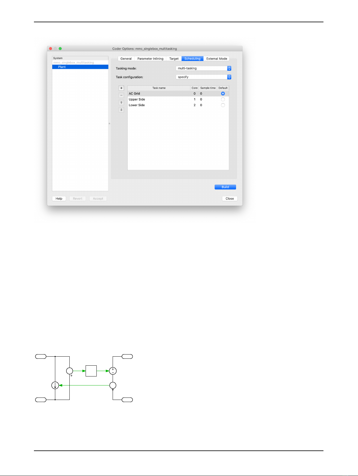
This RT Box demo model features a grid-connected modular multilevel converter (MMC) with open-
loop controls. The demo model can be simulated either in single-tasking or multi-tasking mode. To al-
low multi-tasking mode, the physical model has to be split into different parts. This can be done with
the Task Frame component from the PLECS library. This block associates the enclosed components
with a specified task in a multi-tasking environment. For real-time simulation on the RT Box 2 or RT
Box 3 each specified task is then executed on a different CPU core to reduce the overall discretization
step size. For the PLECS RT Box 1 only single-tasking mode is available. The chosen discretization
step size and average execution times for the two different tasking modes are shown in Tab. 1.
Table 1: Discretization step size and average execution time of real-time models with both tasking
modes for 5 submodules per arm on RT Box 2
Discretization Step Size Average Execution Time Single-Tasking Average Execution Time Multi-Tasking
6µs3.7 µs2.0 µs
1.1 Requirements
To run this demo model, the following items are needed (available at www.plexim.com):
• One PLECS RT Box 1, 2 or 3 and one PLECS Coder license
• One 37 pin Sub-D cable to connect the digital I/Os of the box front-to-front
• The RT Box Target Support Library
• Follow the step-by-step instructions on configuring PLECS and the RT Box in the Quick Start guide
of the RT Box User Manual.
Note This model contains model initialization commands that are accessible from:
PLECS Standalone: The menu Simulation + Simulation Parameters... + Initializations
PLECS Blockset: Right click in the Simulink model window + Model Properties + Callbacks +
InitFcn*
2 Model
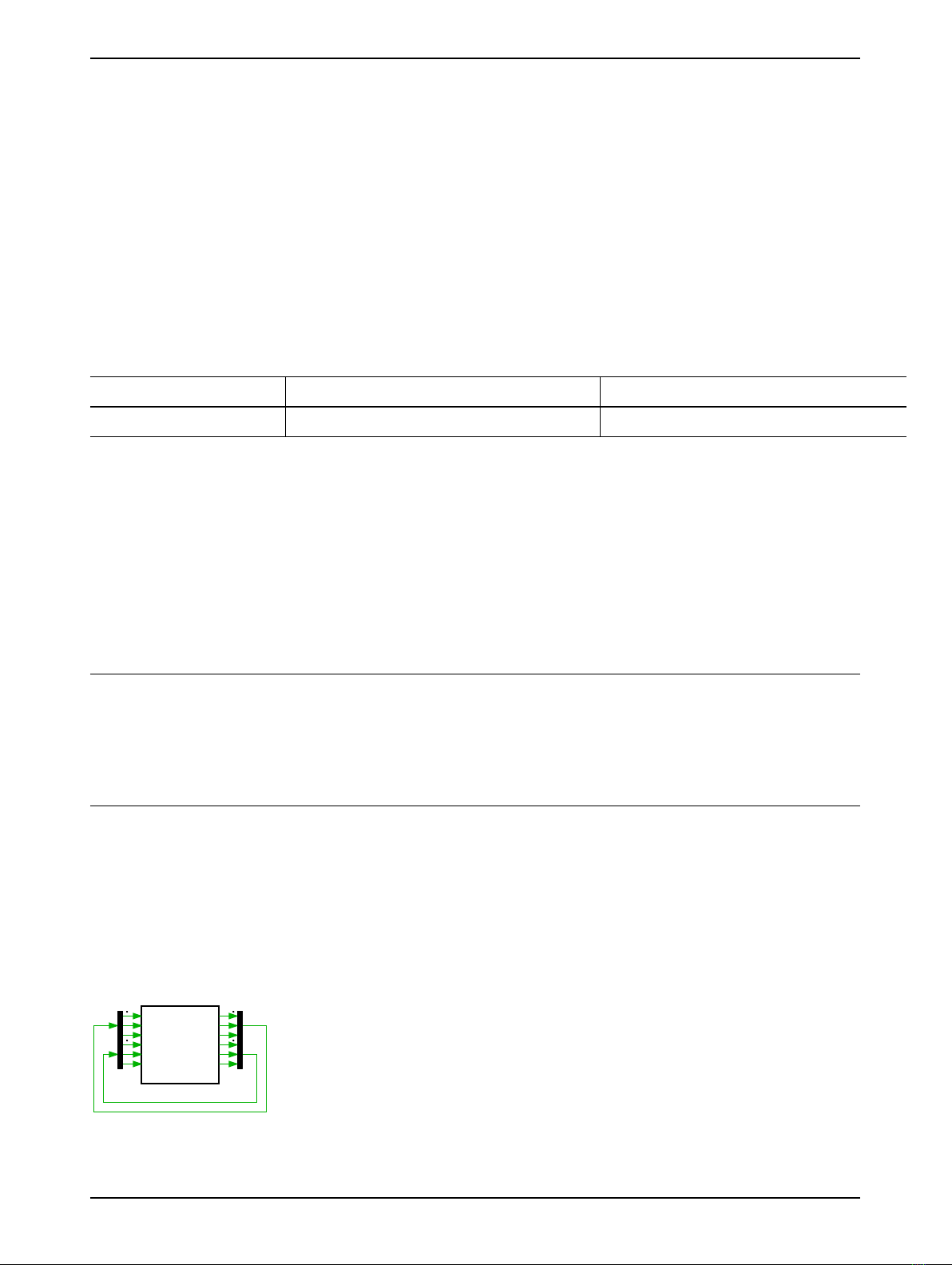
The top level schematic of the demo model is depicted in Fig. 1. Since the demo model runs in open-
loop, the PWM generation and the power circuit run on the same RT Box. To run the subsystem on
an RT Box, the subsystem has to be configured as atomic and enabled for code generation by right-
clicking on the subsystem and choosing Subsystem +Execution settings....
Plant+OpenloopControls
Swa
PWMa
Swb
PWMb
Swc
PWMc
PWMa1
Swa1
PWMb1
Swb1
PWMb2
Swc1
Figure 1: Top level schematic of MMC demo model
www.plexim.com 1

Modular Multilevel Converter
2.1 Power Circuit
Fig. 2 shows the circuit model of the “Plant”, which comprises an MMC connecting the AC system and
the DC system. The MMC has a configurable number of submodules per arm with a default value of
5. Every submodule is composed of one full-bridge and a DC-link capacitor and each single-phase pair
of converter arms, together with their arm inductors, is then connected to the AC grid. The converter
arms are implemented with the Full Bridges (Series Connected) power module library component.
This component has two configurations: a Switched implementation where ideal switches represent
the semiconductors, and an sub-cycle averaged configuration that uses controlled voltage and current
sources. This model is configured to use the Sub-cycle averaged implementation of the power module
components which is suitable for offline and real-time simulation.
The implementation of both the power module and the PWM generation is such that the number of
cells can be configured with a variable num_sm in the Model initialization commands without having to
extend the model with additional wiring or components. This concept is called implicit vectorization of
the model structure and is further explained in the tutorial “Implicit Model Vectorization” available in
the tutorials section of the Plexim website.
Swa
PWM
Capture
PWMa
PWM
Out
ma
Qa+1
Qa+4
Qa+2
Qa+3
U(I)
Qa-2
Qa-3
Qa-1
Qa-4
Swb
PWM
Capture
PWMb
PWM
Out
mb
Qb+1
Qb+4
Qb+2
Qb+3
Qb-2
Qb-3
Qb-1
Qb-4
Swc
PWM
Capture
PWMc
PWM
Out
mc
Qc+1
Qc+4
Qc+2
Qc+3
Qc-2
Qc-3
Qc-1
Qc-4
U(I)
U(I)
U(I)
U(I)
U(I)
U(I)
U(I)
U(I)
U(I)
U(I)
U(I)
U(I)
U(I)
U(I)
PWMa1
PWM
Out
Swa1
PWM
Capture
PWMb1
PWM
Out
Swb1
PWM
Capture
PWMb2
PWM
Out
Swc1
PWM
Capture
Qa+3
Qa+4
Qa+1
Qa+2
Qa-3
Qa-4
Qa-1
Qa-2
V_3ph
Qb+3
Qb+4
Qb+1
Qb+2
Qb-3
Qb-4
Qb-1
Qb-2
Qc+3
Qc+4
Qc+1
Qc+2
Qc-3
Qc-4
Qc-1
Qc-2
V_dc
Model
Settings
Model
Settings
Model
Settings
Model
Settings
Model
Settings
Model
Settings
Model
Settings
V
UpperSide
UpperSide
UpperSide
LowerSide
LowerSide
LowerSide
Measurements
Figure 2: Schematic of the grid-connected MMC inverter
Tasking modes
In order to distribute the physical model on different CPU cores of the RT Box 2/3, the model has to be
split with the Task frame component from the PLECS library. The tasking mode can be configured in
the Coder Options in the Scheduling tab of the Coder Options window, as shown in Fig. 3.
Single-tasking If the Tasking mode is configured as single-tasking, all task frame components
are ignored and the physical system is executed in a single base task. This configuration is needed for
real-time simulation of the demo model on the RT Box 1.
www.plexim.com 2

Modular Multilevel Converter
Figure 3: Scheduling task in the Coder Options
Multi-tasking If the Tasking mode is configured as Multi-tasking the physical model is split into
three different tasks and those tasks are associated with the three available CPU cores of the RT Box
2/3, as shown in Fig. 3.
The physical model is split as follows:
• Core 0: AC Grid and phase inductance/resistance and DC bus
• Core 1: All high-side sub-cells and DC-link capacitors
• Core 2: All low-side sub-cells and DC-link capacitors
To allow this system splitting, the physical model has to be split at strategic locations by using a
coupling circuit. To do so, a controlled current source is placed in one part of the model and a con-
trolled voltage source in the other part. Both sources are controlled by the respectively measured volt-
age/current state variables from the other part of the model. To avoid state/source dependence, one
measured signal has to be delayed by one discretization step. This approach is shown in Fig. 4.
A
z-1
V
1
2
3
4
Figure 4: Circuit to allow physical system splitting
The individual CPU load for each core becomes smaller and due to this, the average execution time
can be reduced considerably. A reduced discretization step size leads to a better frequency resolution,
www.plexim.com 3

Modular Multilevel Converter
and therefore fidelity of the real-time simulation is improved.
2.2 Controls
The demo model is operated in open-loop. The PWM generation is executed in the same box and
routed to the digital output be means of the PWM Out block. Those PWM signals are then feed back
to the digital inputs by using a physical loop-back cable. The PWM signals are then brought into the
real-time simulation with the PWM Capture block.
3 Simulation
This model can run both in offline mode on a computer or in real-time mode on the PLECS RT Box.
Please follow the instructions below to run in real-time mode on an RT Box:
• Connect the Digital In interface to the Digital Out interface of the RT Box, i.e. by using a 37 pin
Sub-D cable.
• From the System tab of the Coder options... window, select the “Plant” and go to the Scheduling
tab. Chose either single-tasking or multi-tasking as the tasking mode and accept your choice.
Please note that multi-tasking mode is only available for RT Box 2 and RT Box 3.
• Return to the System tab, select the “Plant” and Build it onto the RT Box.
• Once the model is uploaded, from the External Mode tab, Connect to the RT Box and Activate
autotriggering.
During the real-time operation under External Mode the measurements can be observed using the
PLECS Scope “Measurements”. The arm voltage and AC grid currents are shown in Fig. 5.
Arm Voltage
Grid current
voltage (V)
-400
-200
0
200
400
× 1e-20.0 0.5 1.0 1.5 2.0 2.5 3.0 3.5
current (A)
-1000
0
1000
Figure 5: Real-time measurements obtained on the RT Box in multi-tasking mode
4 Conclusion
This RT Box demo model demonstrates a grid-connected MMC inverter under open-loop control. The
demo model can run both in single-tasking mode on one CPU core of the RT Box 1, 2 or 3, or in multi-
tasking mode on three CPU cores of the RT Box 2 or 3. Multi-tasking has the benefit that the average
execution time can be reduced considerably.
www.plexim.com 4

Revision History:
RT Box TSP 2.0.5 First release
How to Contact Plexim:
+41 44 533 51 00 Phone%
+41 44 533 51 01 Fax
Plexim GmbH Mail)
Technoparkstrasse 1
8005 Zurich
Switzerland
http://www.plexim.com Web
RT Box Demo Model
© 2002–2020 by Plexim GmbH
The software PLECS described in this document is furnished under a license agreement. The software
may be used or copied only under the terms of the license agreement. No part of this manual may be
photocopied or reproduced in any form without prior written consent from Plexim GmbH.
PLECS is a registered trademark of Plexim GmbH. MATLAB, Simulink and Simulink Coder are regis-
tered trademarks of The MathWorks, Inc. Other product or brand names are trademarks or registered
trademarks of their respective holders.
Table of contents
Other Plexim Media Converter manuals