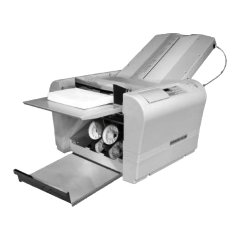
Plockmatic SQF-200 SquareFolder User manual

Provided By
http://www.MyBinding.com
http://www.MyBindingBlog.com
Plockmatic SQF200
Squarefolder
Service Manual

SQUAREFOLDER SQF 200
SERVICE MANUAL
12 February 2007
Subject to change

Page intentionally blank

V
29 November 2006
TABLE OF CONTENTS
1 INSTALLATION PROCEDURE
1.1 INSTALLATION PROCEDURE........................................................SQF-1-1
2 PREVENTIVE MAINTENANCE SCHEDULE
2.1 PREVENTIVE MAINTENANCE SCHEDULE..................................SQF-2-1
3 REPLACEMENT AND ADJUSTMENT
3.1 COVERS..........................................................................................SQF-3-1
3.1.1 FRONT COVER......................................................................SQF-3-1
3.1.2 REAR COVER ........................................................................SQF-3-2
3.1.3 INFEED COVER.....................................................................SQF-3-3
3.1.4 OUTFEED COVER.................................................................SQF-3-4
3.1.5 TOP COVER...........................................................................SQF-3-6
3.1.6 TILT THE MACHINE ...............................................................SQF-3-7
3.2 MOTORS.........................................................................................SQF-3-9
3.2.1 TRANSPORT BELT MOTOR (M1)..........................................SQF-3-9
3.2.2 STOP GATE MOTOR (M2) ...................................................SQF-3-10
3.2.3 CLAMP MOTOR (M3)...........................................................SQF-3-11
3.2.4 ROLLER MOTOR (M4)AND PRESSURE ROLLER.............SQF-3-12
3.3 SENSORS AND SWITCHES.........................................................SQF-3-15
3.3.1 STOP GATE SENSOR (Q1)..................................................SQF-3-15
3.3.2 ROLLER MOTOR FRONT/REAR SENSORS (Q2AND Q3)SQF-3-16
3.3.3 CLAMP MOTOR HOME POSITON SENSOR (Q4) ..............SQF-3-17
3.3.4 INFEED / OUTFEED SENSORS (Q5 AND Q7)....................SQF-3-18
3.3.5 CLAMP SENSOR (Q6)..........................................................SQF-3-20
3.3.6 MOTOR M4 ENCODER SENSOR (Q8)................................SQF-3-21
3.3.7 TOP COVER INTERLOCK SWITCHES (S2 & S4)...............SQF-3-22
3.3.8 UPPER TRANSPORT BELT CLUTCHES (SOL1 & SOL3)...SQF-3-23
3.3.9 LOWER TRANSPORT BELT CLUTCHES (SOL2 & SOL4)..SQF-3-24
3.4 BELTS............................................................................................SQF-3-25
3.4.1 UPPER TRANSPORT BELT.................................................SQF-3-25
3.4.2 LOWER TRANSPORT BELT ................................................SQF-3-26
3.4.3 TEFLON TAPE LOWER TRANSPORT BELT ....................SQF-3-29
3.5 MECHANICS.................................................................................SQF-3-31
3.5.1 SET CLAMPS........................................................................SQF-3-31
3.5.2 STOP GATE..........................................................................SQF-3-34
3.6 PCB ...............................................................................................SQF-3-37
3.6.1 PCB MD6DC “D”...................................................................SQF-3-37
3.7 POWER REQUIREMENTS...........................................................SQF-3-39
3.7.1 TAPPING THE TRANSFORMER..........................................SQF-3-39
4. TROUBLESHOOTING
4.1 FAULT CODE DESCRIPTIONS.......................................................SQF-4-1
4.2 BLOWN FUSE CONDITION..........................................................SQF-4-13
4.3 LED’S.............................................................................................SQF-4-15
4.4 TEST POINTS...............................................................................SQF-4-17
VI
29 November 2006
5 SERVICE TABLES
5.1 SERVICE TABLES...........................................................................SQF-5-1
6. DETAILED SECTION DESCRIPTION
6.1 ELECTRICAL COMPONENT LIST..................................................SQF-6-1
6.1.1 COMPONENT LAYOUT..........................................................SQF-6-2
6.2 BOARD STRUCTURE .....................................................SQF-6-5
6.2.1 CONTROLLER MD6DC “D”....................................................SQF-6-5
6.3 PRINCIPLE OF OPERATION..........................................................SQF-6-7
SPECIFICATIONS
SPECIFICATIONS..............................................................................SQF-Spc-1
WIRING
Squarefolder........................................................................................SQF-Wir-1

SQF-1-1
29 November 2006
Installation
1 INSTALLATION PROCEDURE
1.1 INSTALLATION PROCEDURE
Squarefolder installation procedure is located in the Booklet Maker BM 200
Service Manual ( 1.6)

Page intentionally blank

SQF-2-1
29 November 2006
Preventive
Maintenance
2 PREVENTIVE MAINTENANCE SCHEDULE
2.1 PREVENTIVE MAINTENANCE SCHEDULE
Squarefolder preventive maintenace schedule is located in the Booklet Maker BM
200 Service Manual ( 2)

Page intentionally blank

SQF-3-1
Replacement
Adjustment
29 November 2006
3 REPLACEMENT AND ADJUSTMENT
3.1 COVERS
3.1.1 FRONT COVER
COVERS
[A]
Removal
1. Open top cover.
2. Remove screws [A] ( x 3 ).
3. Remove screws [B] ( x 2 )
[A]
[B]

SQF-3-2
29 November 2006
3.1.2 REAR COVER
[A] [A]
Removal
1. Loosen screws [A] ( x 2 ).
NOTE: Lift out lower part and unhook the Rear cover.
COVERS

SQF-3-3
Replacement
Adjustment
29 November 2006
3.1.3 INFEED COVER
[A]
Removal
1. Open Top cover.
2. Remove nuts [A] ( x 4 ).
3. Remove nuts [B] and remove locking bracket ( x 2 ).
4. Tilt machine ( 3.1.6 ).
5. Remove nuts [C] ( x 2 ).
Replacement
4. Reverse the removal procedure.
NOTE: Make sure that the springs to the Upper Transport Belts are in correct
position.
[A]
[C]
COVERS
[B]
Bottom view

SQF-3-4
29 November 2006
3.1.4 OUTFEED COVER
COVERS
[A]
Removal
1. Remove Top cover gas spring lower end from joint [A].
NOTE: Press plastic stud from pivot point.
2. Remove screws [B] ( x 2).
3. Remove Front and Rear cover ( 3.1.1, 3.1.2 ).
4. Remove screws [C] ( x 2).
5. Remove Belt Stacker hangers [E] ( x 2).
6. Remove screws [F] ( x 4).
7. Lift Out feed cover carefully and disconnect wiring to sensor Q7 Phototransistor
[G] ( x 1).
[C]
[B]
Front view
Rear view
[D]

SQF-3-5
Replacement
Adjustment
29 November 2006
[E]
[F]
[G]
Top view, Outfeed
cover slightly tilted

SQF-3-6
29 November 2006
3.1.5 TOP COVER
Removal
1. Open Top cover.
2. Remove Top cover gas spring lower end from joint [A].
NOTE: Press plastic stud from pivot point.
3. Remove screws [B] ( x 4).
[B]
[A]
COVERS
Bad
Top cover too low Good Bad
Top cover too high

SQF-3-7
Replacement
Adjustment
29 November 2006
3.1.6 TILT THE MACHINE
Removal
1. Remove Belt stacker ( Service manual BM 200 3.8.1).
2. Remove the Trim bin.
3. Remove the Service bracket [A] by removing two nuts ( x 2 ).
4. Remove the foot screw [C] and mount it in the oposite hole up-side-down.
5. Place the Service bracket [B] in the Squarefolder base.
6. Turnfootscrew[C]ontheServicebracket,untiltheServicebracketrmly
contactstheoor.
7. Remove the screw [D] securing the machine with the base.
8. Remove Front cover ( 3.1.1).
9. Remove Rear cover ( 3.1.2).
10.Loosen screws [E] half a turn. One on each side ( x 2).
COVERS
[A]
[B]
[C]
[D]
WARNING
Squarefolder may Tip. Install Service bracket before separating the Square-
folder from the Trimmer.
WARNING
Before tilting make sure pivot screws [E] are NOT tightened.
Infeed view Infeed view
from below

SQF-3-8
29 November 2006
11.Remove screws [F]. One on each side ( x 2).
NOTE: Keep the screws. They will be used later in this procedure.
[F]
COVERS
Front view Rear view
Front view,
machine tilted Rear view,
machine tilted
CAUTION
When lowering or raising the machine, lift in infeed area only.
[G]
[E]
12.Tilt machine by lifting infeed cover.
13.Secure machine with both the screws [G]. One on each side. Use the screws
previously removed from [F]. ( x2).
WARNING
When tilting SQF 200, make sure to tighten BOTH screws [G],
one on each side.

SQF-3-9
Replacement
Adjustment
29 November 2006
Removal
1. Tilt machine ( 3.1.6).
2. Remove R-pin [A] ( x 1).
3. Remove sprocket [B].
4. Disconnect the motor connectors ( x 2) .
5. Remove screws [C] ( x 4).
6. Remove Motor.
Replacement
1. Reinstall the motor, and secure it by tighten screws [C] ( x 4).
2. Connect the motor connectors ( x 2) .
NOTE: The Orange wire on ”+”, and the Violet wire on ”-”.
3. Reverse the rest of the removal procedure.
3.2 MOTORS
3.2.1 TRANSPORT BELT MOTOR (M1)
MOTORS
M1
[C]
[A] [B]

SQF-3-10
29 November 2006
3.2.2 STOP GATE MOTOR (M2)
MOTORS
M2
Removal
1. Tilt machine ( 3.1.6).
3. Remove cam by loosening allen screw [A] ( x 1).
4. Remove screws [B] ( x4).
5. Disconnect the Motor ( x 2).
6. Remove Motor.
Replacement
1. Reinstall the motor, but do not tighten screws [B] ( x 4).
2. Connect the motor connectors ( x 2) .
NOTE: The Orange wire on ”+”, and the Violet wire on ”-”.
3. Reverse the rest of the removal procedure.
4. Perform Stop Gate adjustment B ( 3.5.2).
[A] [B]

SQF-3-11
Replacement
Adjustment
29 November 2006
3.2.3 CLAMP MOTOR (M3)
Removal
1. Remove Outfeed Cover ( 3.1.4 ).
2. Remove the E-Clips and Washers [A] ( x 2, x 2).
3. Remove the driving disc [B] by loosening allen screw ( x 1).
4. Disconnect the motor connectors ( x 2).
5. Remove screws [C] holding Motor bracket ( x 4).
6. Remove screws holding Motor bracket ( x 3).
Replacement
1. Mount Motor to Motor bracket ( x 3).
2. Reinstall motor, by tighten screw [C] ( x 4).
3. Connect the motor connectors ( x 2) .
NOTE: The Orange wire on ”1”, and the Violet wire on ”2”.
4. Reverse the rest of the removal procedure.
MOTORS
M3
[A][C] [C][B]
[C]
CAUTION
Be careful not to damage sensor SQF-Q4
[SQF-Q4]
Table of contents
Popular Folding Machine manuals by other brands

Dahle
Dahle 10560 operating instructions

MBO
MBO America B115 Operator's manual

Formax
Formax FD 332 Operator's manual

Hefter
Hefter TF MEGA-A instruction manual

FP Mailing Solutions
FP Mailing Solutions FPi 4700 installation guide

Martin Yale
Martin Yale intimus 2020VS Installation, maintenance & operating instructions

Martin Yale
Martin Yale 1811 operating manual

Martin Yale Indastries
Martin Yale Indastries 1217A Installation, maintenance & operating instructions

Magnum
Magnum MFM-PS Product instruction manual

Pressure Seal Group
Pressure Seal Group PS 600 Operator's manual

Morgana
Morgana Digifold 5000P Operator's manual

Galaxy
Galaxy PH40V instruction manual