Please take the time and read these operating instructions before use and
retain them for future reference. Failure to follow these instructions may lead to serious
injury and damage to property.
2. Safety Notes
1. When measuring, do not enter a limit that exceeds the range.
2. When changing the function and range, the test leads should leave the test point.
3. In the resistance mode, please do not add voltage to the input.
In general, if something unusual happens or if you suspect that something is wrong or has
malfunctioned, do not do anything with the product and immediately contact the seller for
3. General Characteristics
- Maximum display value: 1999 (31/2) bit, automatic polarity display
- Sampling rate: about 3 times per second
- Over range indication: the highest bit is "1"
- Low voltage display: " " symbol appears
- Working environment: (0~40) °C, relative humidity < 80%
- Power: 3 V battery (2 x AAA)
- Accuracy: ± (reading % + the least significant digits)
- Ambient temperature: (23±5) °C, relative humidity < 75%, calibration guarantee period for
one year from the day of production.
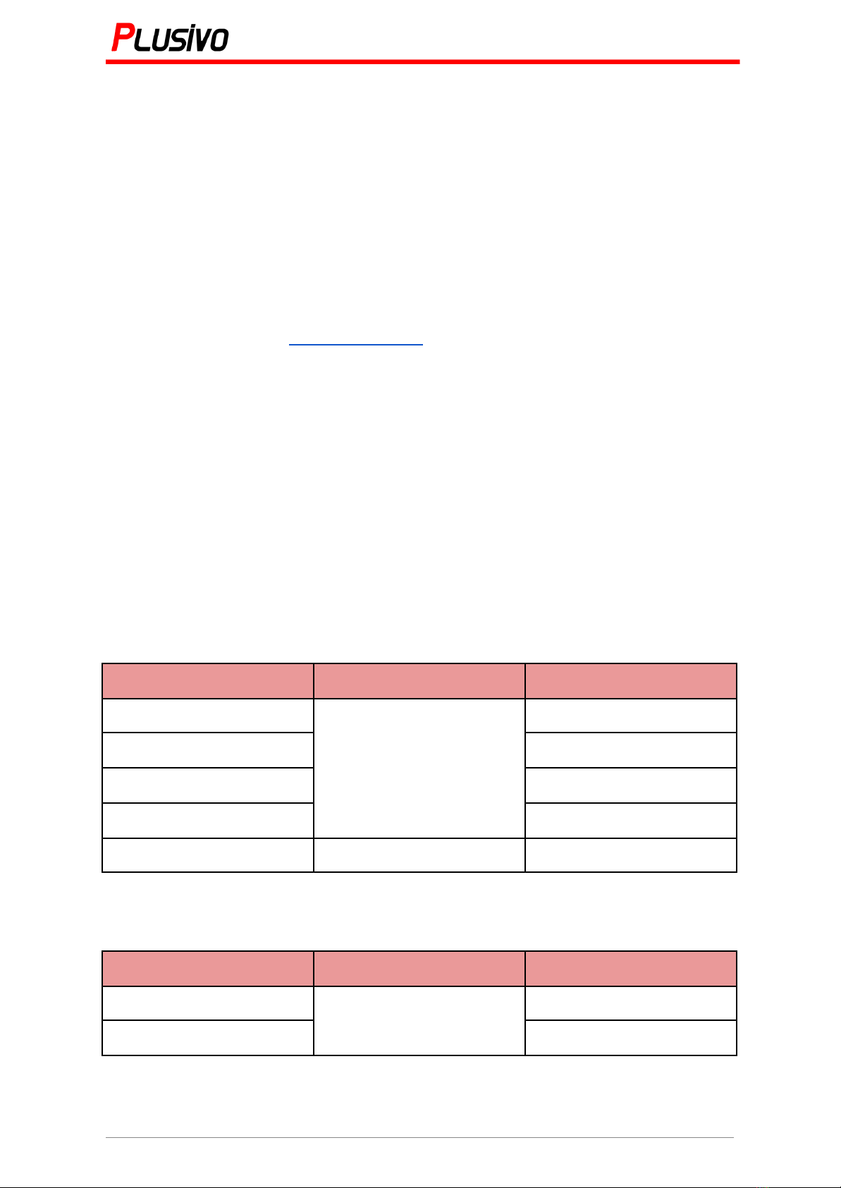
3.1 DC Voltages (DC Volts)