PLX Legion Solar User manual

Legion Solar Installation and Operations Manual
V3.1 March 26, 2021
www.legionsolar.com
+1 (408)745-7591
1
Read this material before using this product. Failure to do so can result in
serious injury, property damage, and/or electrical shock.
SAVE THIS MANUAL
Keep this manual for safety warnings, precautions, operating, installation, inspection, and
maintenance procedures. Write the product’s device ID numbers in the back of the manual.

Legion Solar Installation and Operations Manual
Important Safety Information 4
Read this First 4
Safety Instructions 4
Legion Solar Overview 5
Included Items 7
Location Planning 8
Optimal Tilt Angle 8
Optimal Direction 8
Mounting Solutions 9
Hardware Installation 9
Install the MicroInverter to the Photovoltaic Panel 9
Install the Battery Commander to the Photovoltaic Panel 11
Install ‘Z’ Brackets for Do-it-Yourself Mounting 11
Electrical Installation 12
Connect the DC Wires (Inverter Only) 12
Connect the DC Wires (Inverter + Battery Commander) 13
Connect the Battery (Lithium) 14
Connect the Battery (Lead Acid) 15
Connect the AC Wires 17
Maximum System Size 17
Grid Connection Method1: Plug and Play 18
Grid Connection Method2: Hardwire 19
Wire Selection Guide 20
AC Connection Schematic 21
Expanding your System 22
Installing Solar Regulator 23
Installing OffGrid Controller and OffGrid Inverter 24
Troubleshooting 28
MicroInverters 28
Battery Commander V2.0 28
Battery Commander V1.0 29
Solar Regulator 30
Copyright © 2021 PLX Devices Inc.
2

Legion Solar Installation and Operations Manual
OffGrid Controller 30
OffGrid Inverter 31
Helpful Videos 31
Helpful 3rd Party Tools 31
Maintenance 33
Technical Data 33
Device IDs 38
PV Panel Drawing 39
Part Descriptions 40
230VAC Micro Inverters on 120VAC Grids 41
Legion Solar with Utility Approved Grid Tied Solar Systems 41
Warranty 41
Limitations of Liability 42
Service and Support 42
Copyright © 2021 PLX Devices Inc.
3

Legion Solar Installation and Operations Manual
Important Safety Information
Read this First
This document contains instructions for use during installation and maintenance of Legion Solar System.
To reduce the risk of electrical shock, and to ensure the safe installation and operation of Legion Solar
System, pay close attention to following safety symbols that appear throughout this document.
DANGER! A hazardous condition, if not avoided, will result in death, serious injury, equipment or
property damage.
WARNING! A hazardous condition, if not avoided, could result in death, serious injury,
equipment or property damage.
WARNING! An electrical condition, if not avoided, could result in death, serious injury, fire,
equipment or property damage. Use extreme caution and follow instructions carefully.
Safety Instructions
• Before installing or using Legion Solar System, read all instructions and cautionary markings in this
document.
• Do not use Legion Solar equipment in a manner not specified by the manufacturer. Doing so may
cause death or injury to persons, or damage to equipment and/or property.
•Only qualified personnel should install or replace Legion Solar components and accessories.
• Perform all electrical installations in accordance with all applicable electrical and local jurisdiction
codes.
• The DC conductors of this photovoltaic system are ungrounded and may be energized.
• Do not attempt to repair the MicroInverter, Battery Commander, OffGrid Controller, OffGrid Inverter
and/or any Legion Solar components/accessories. They contain no user serviceable parts. If it fails
contact PLX Devices customer service to obtain an RMA (return merchandise authorization).
Tampering with Legion Solar components will void the warranty.
• If the AC cable and/or connectors are broken or damaged, do not install the unit.
• Wear gloves when handling the PV panels to avoid injury, as some edges may be sharp.
• The MicroInverter may get hot during operation can and reach temperatures above 80°C (176° F). To
reduce the risk of burns, use caution when working with MicroInverters.
• Do NOT disconnect the photovoltaic modules from the MicroInverter without first disconnecting the
AC power.
Copyright © 2021 PLX Devices Inc.
4

Legion Solar Installation and Operations Manual
Legion Solar Overview
Legion Solar is a permission free off-grid solar system with on-grid benefits. The Photovoltaic panels are
high efficiency ‘A’ Grade silicon and specifically designed to be lightweight enough for one person to
handle. The high efficiency MicroInverters installed on the rear of the PV panel simplifies the design and
maximizes energy production efficiency. Legion Solar’s optimized design methodology makes the system
modular, low cost, high output, easy to install and features inverter anti-islanding for safety. Legion Solar
is designed to outperform all other solar system solutions with the best price/performance ratio on the
market thus enabling you to achieve higher energy production and faster return on investment in both
day and night conditions.
Stage 1 - Get familiar with Legion Solar and it's components with the Starter Set. Sets up in minutes and
experience instant results. A 300W Starter Set is enough to make a noticeable impact to your electric bill.
Stage 2 - Scale your solar output with expansion sets to offset more of your daytime usage.
Copyright © 2021 PLX Devices Inc.
5

Legion Solar Installation and Operations Manual
Stage 3 - Once your system is large enough to have excess energy to store during daytime, add
expansion sets with BatteryCommander™ for night time consumption. BatteryCommander™ enables the
solar panels to charge the batteries, solar panels to supply power to the micro inverters, and batteries to
supply power to the micro inverters.
Stage 4 - Add OffGridController™ and an offgrid inverter so that you have emergency power during grid
power outages. OffGrid controller is a battery capacity multiplier and grid power outage detector. When
grid power goes out, it automatically supplies power to your OffGrid Inverter. OffGrid Inverter converts
battery energy to grid compatible power so that you can power your appliances.
Copyright © 2021 PLX Devices Inc.
6

Legion Solar Installation and Operations Manual
Included Items
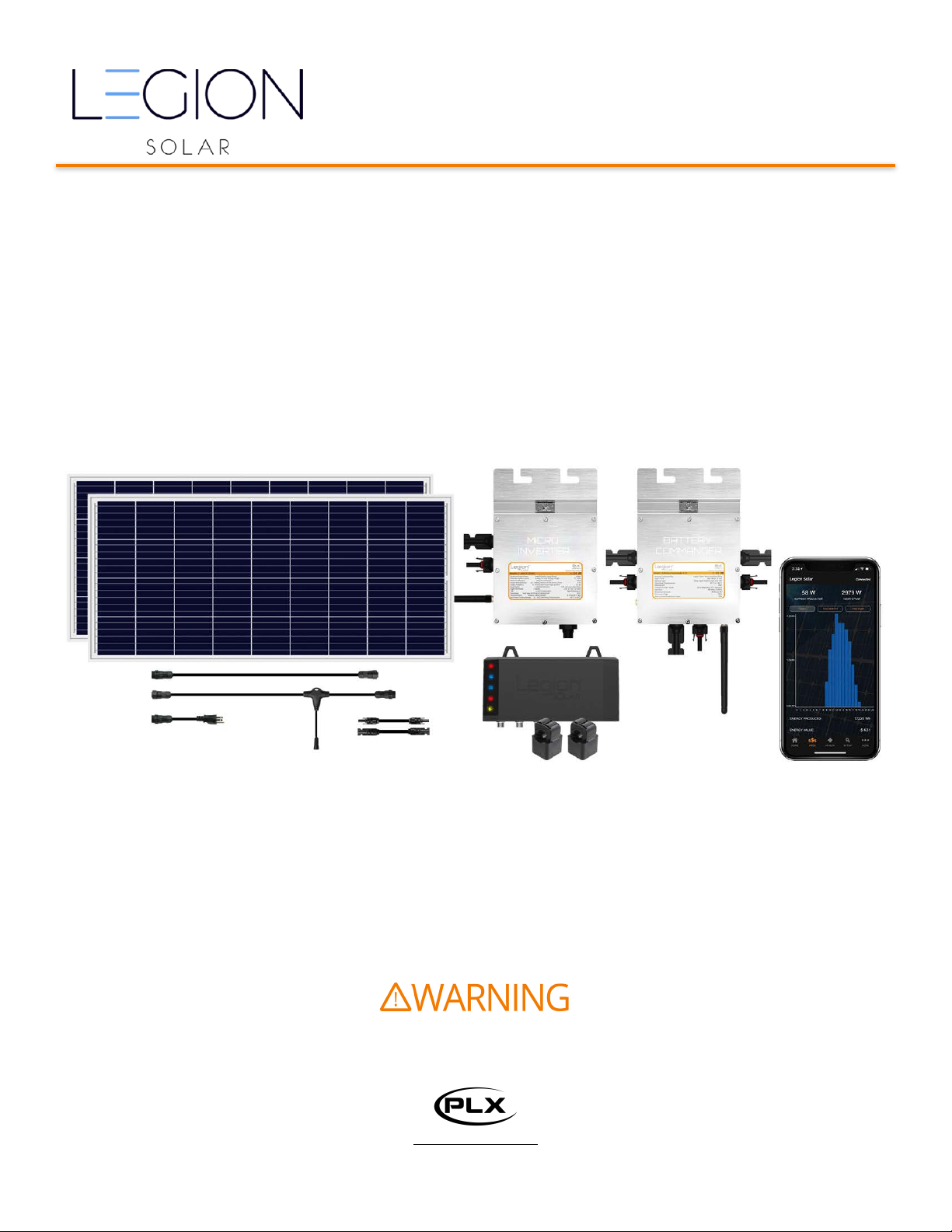
Legion Solar Starter Set
• 1QTY Legion Solar Installation and Operations Manual
• 1QTY Legion Solar Regulator with Bluetooth
• 2QTY Split Core Transformers
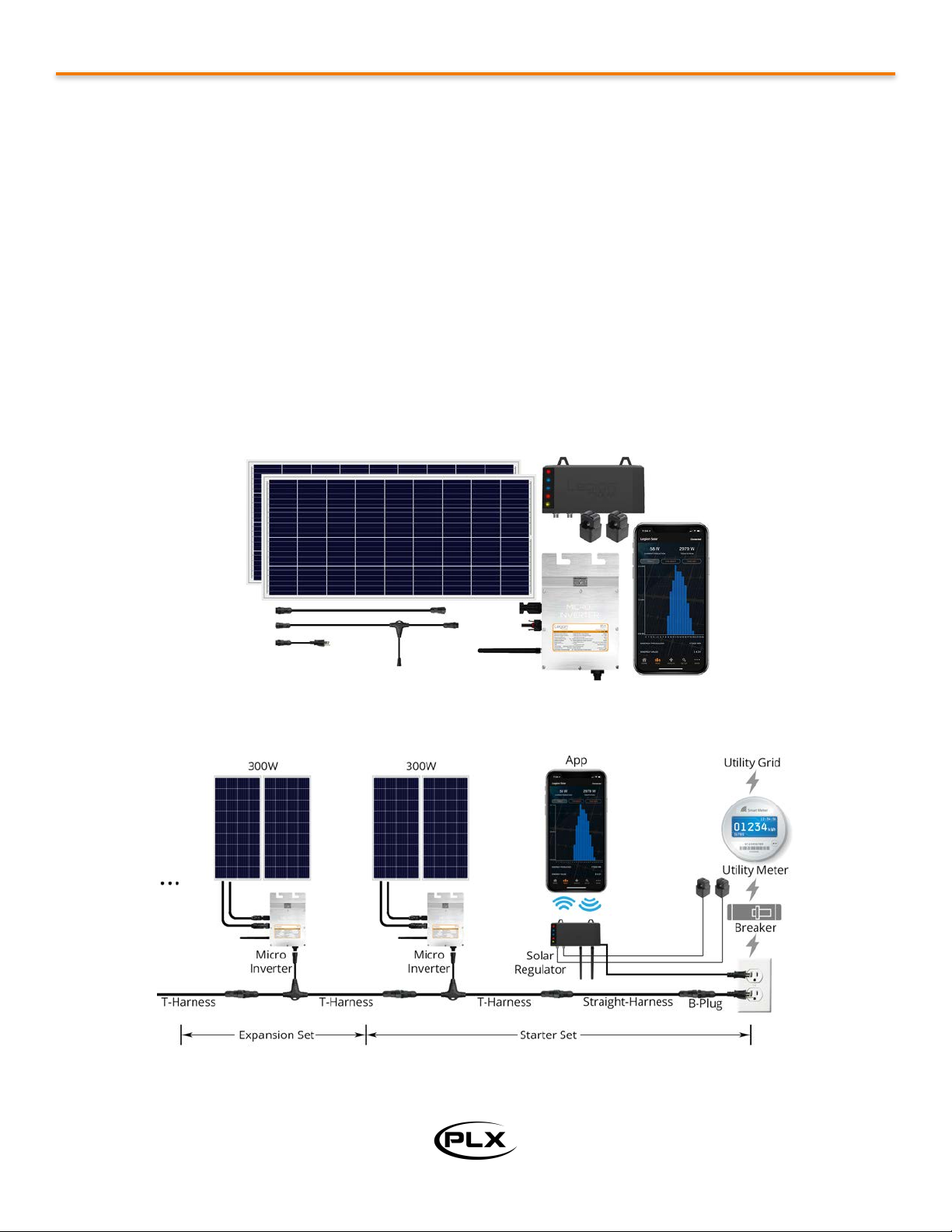
• 2QTY 150Watt LS-150P PhotoVoltaic Panels
• 8QTY Aluminum ‘Z’ Brackets for DIY Mounting Solution
• 8QTY Hex Screw Fine Thread 28 A2-70 0.25" x 5/8”
• 8QTY Nut Fine Thread 28 A2-70 0.25”
• 8QTY Washer A2-70 0.25”
• 8QTY Lock Washer A2-70 0.25”
• 8QTY Self Drill Screw with Plastic Spacer 32mm long 5.0 x 32mm M8
• 1QTY 260Watt LS-260I-xx0VAC MicroInverter
• 1QTY LS-THarness-Vx AC 4ft T-Harness
• 1QTY LS-SHarness-Vx AC 4ft Straight-Harness
• 1QTY LS-PlugNPlay-TypeX AC 1ft Plug and Play Adapter
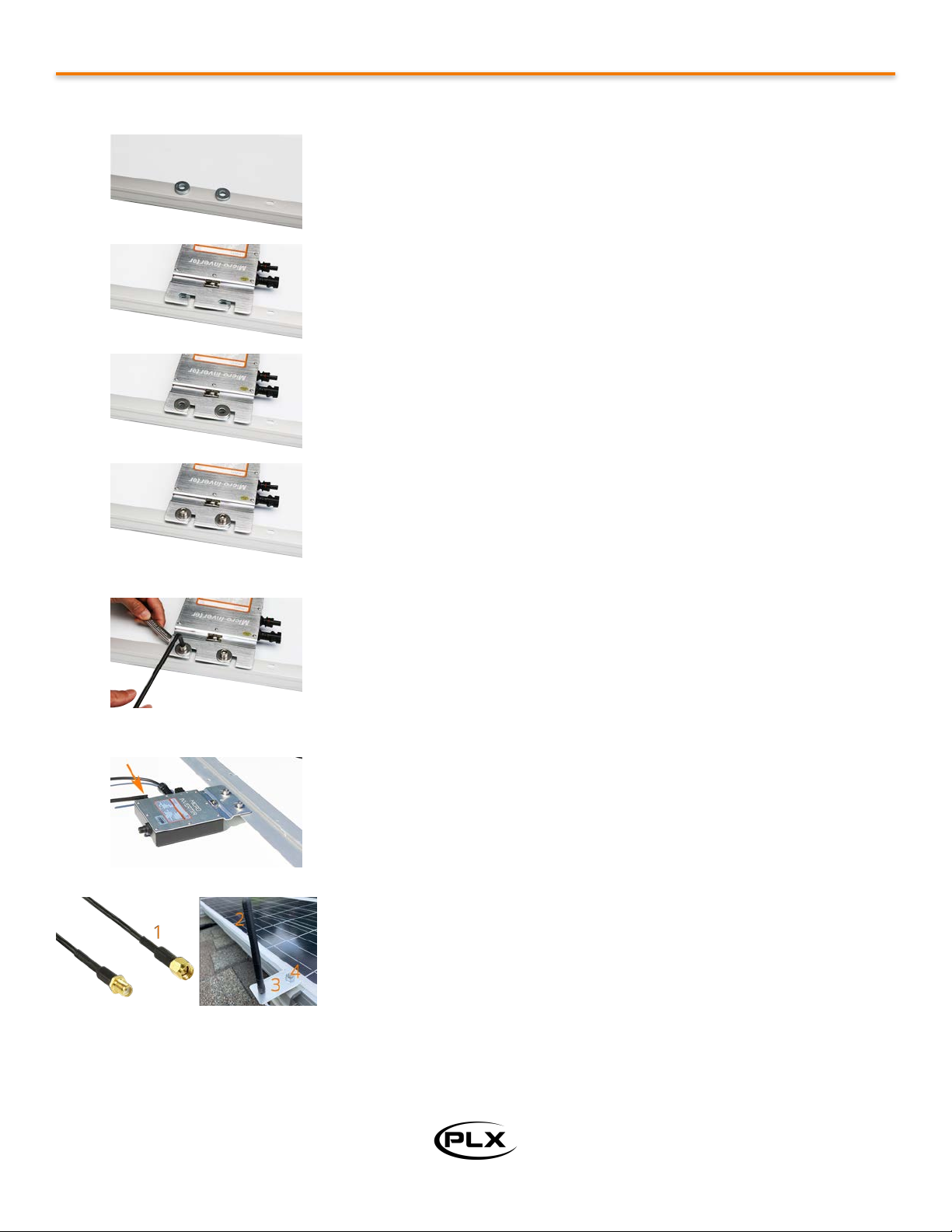
• 2QTY Hex Screw Thread 1.25mm M8 x 20mm long
• 2QTY Hex Nut Thread 1.25mm M8
• 2QTY Lock Washer M8
• 1QTY 3ft SMA Antenna Wire Extension Cable
• 1QTY Antenna Aluminum Bracket
• 1 QTY 2.4GHz Antenna
• 4QTY Washer M8
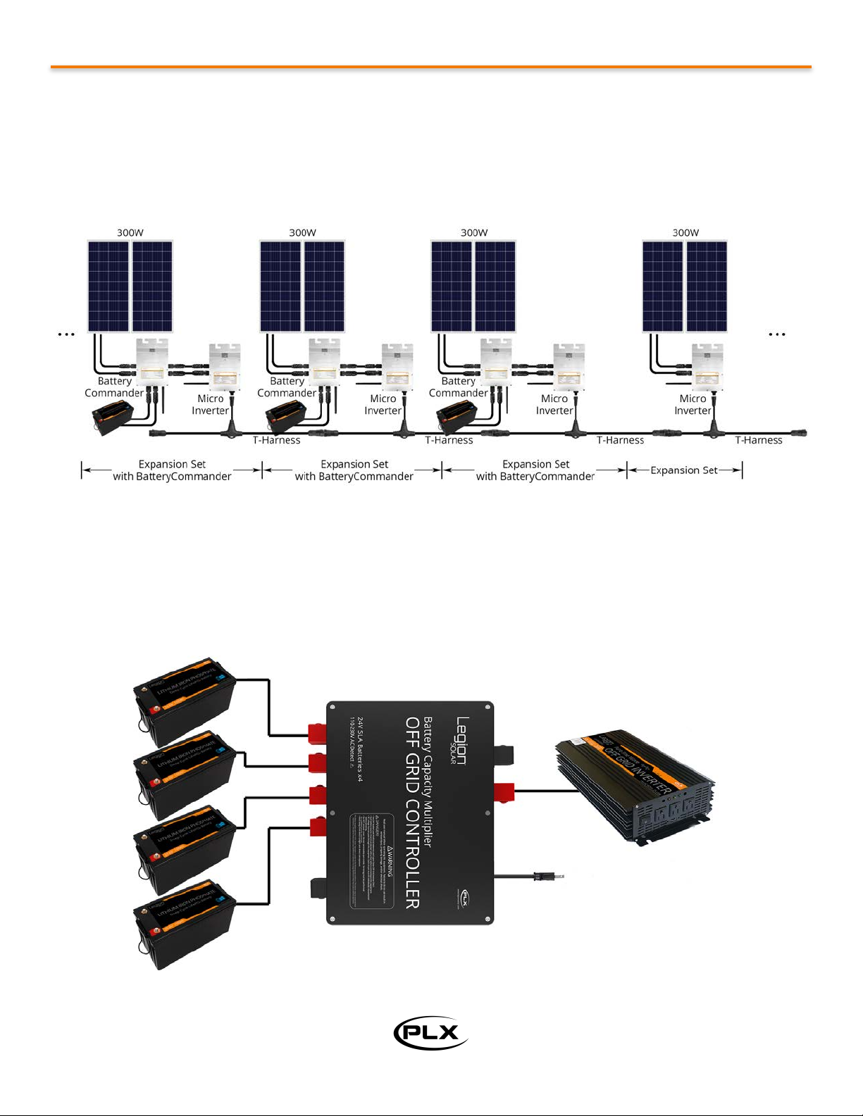
• *1QTY Battery Commander
• *1QTY Set of MC4 Male-Male, Female-Female Wire
• *2QTY Hex Screw Thread 1.25mm M8 x 20mm long
• *2QTY Hex Nut Thread 1.25mm M8
• *2QTY Lock Washer M8
• *1QTY 150A Fuse Wire
• *2QTY Set of Positive and Negative Lead Acid Battery Terminals
• *2QTY Set of Positive and Negative Silicone Battery Terminal Covers
• *1QTY 3ft SMA Antenna Wire Extension Cable
• *1QTY Antenna Aluminum Bracket
• *1 QTY 2.4GHz Antenna
* Included with Deluxe Starter Set or with the addition of Battery Commander with the Basic Starter Set.
Legion Solar Expansion Set
• 1QTY Legion Solar Installation and Operations Manual
• 2QTY 150Watt LS-150M PhotoVoltaic Panels
• 8QTY Aluminum ‘Z’ Brackets for DIY Mounting Solution
• 8QTY Hex Screw Fine Thread 28 A2-70 0.25" x 5/8”
• 8QTY Nut Fine Thread 28 A2-70 0.25”
• 8QTY Washer A2-70 0.25”
• 8QTY Lock Washer A2-70 0.25”
• 8QTY Self Drill Screw with Plastic Spacer 32mm long 5.0 x 32mm Hex is M8
• 1QTY 260Watt LS-260I-xx0VAC MicroInverter
• 1QTY LS-THarness-Vx AC T-Harness
•2QTY Hex Screw
•2QTY Hex Nut
• 2QTY Lock Washer
• 2QTY Washer M8
• 1QTY 3ft SMA Antenna Wire Extension Cable
• 1QTY Antenna Aluminum Bracket
• 1 QTY 2.4GHz Antenna
Copyright © 2021 PLX Devices Inc.
7

Legion Solar Installation and Operations Manual
Location Planning
Optimal Tilt Angle
Tip: Use your smartphone to download a leveler app to measure tilt angle. Calibrate to 0° from a known flat surface.
Optimal Direction
Tip: To achieve a more even power production, spread out your panels facing east, south, west (for northern
hemisphere), or facing east, north, west (for southern hemisphere).
Latitude
Full Year Angle
Latitude
Full Year Angle
0°
0.0°
30°
25.9°
5°
4.4°
35°
29.7°
10°
8.7°
40°
33.5°
15°
13.1°
45°
37.3°
20°
17.4°
50°
41.4°
25°
22.1°
55°
44.9°
Hemisphere
Direction
Production
Northern
True South
Best All Around
Northern
West
Better for peak demand 3pm - 7pm
Southern
True North
Best All Around
Southern
West
Better for peak demand 3pm - 7pm
Copyright © 2021 PLX Devices Inc.
8
Install the PV panels where the entire surface area is
exposed to direct sunlight. Avoid any shaded areas
to achieve maximum energy production.

Legion Solar Installation and Operations Manual
Mounting Solutions
Racking solutions are available from www.legionsolar.com. Tap on SHOP to configure your system and Add to Cart.
All hardware components are automatically calculated. Items that you already own such as Starter and Expansion
Sets can be removed from your shopping cart prior to check out.
Individual Legion Solar components and accessories can also be purchased from www.plxdevices.com. Tap on
LEGION SOLAR.
Detailed step by step how-to videos are available from www.legionsolar.com. Tap on TUTORIALS.
Hardware Installation
Install the MicroInverter to the Photovoltaic Panel
Copyright © 2021 PLX Devices Inc.
9
Step1:
1 MicroInverter is used for every 2 photovoltaic panels.
Locate the 4 round (not oval) holes on the rear of the PV
panel as indicated by the arrows.
If you do NOT have a Battery Commander paired with this
set, install the Micro Inverter in location A.
If you HAVE a Battery Commander paired with this set, install
the Micro Inverter in Location B.

Legion Solar Installation and Operations Manual
Copyright © 2021 PLX Devices Inc.
10
Step2:
Place 2 M8 washers on the frame above the two holes. 1
washer per side.
Step3:
Place the MicroInverter on top washers and align the holes
with the 2 L shaped notches.
Step4:
Place 2 M8 washers on top of the L shaped notches. Align the
washers with the hole.
Step5:
Insert the 2 Hex Screw Thread 1.25mm M8 x 20mm long into
the hole making sure the screw goes through the washers.
Step6:
Insert the lock washer M8 followed by the Hex Nut Thread
1.25mm M8. Tighten the screws with 6mm hex key and
14mm wrench.
Step7:
Install the Antenna. If the Inverter is within 30ft of Solar
Regulator and is unobstructed by dense materials such as
metal, concrete, brick, tile you may install the Antenna
directly on the Inverter.
Otherwise, we recommend using the included SMA coax wire
(1) to locate your Antenna (2) out and above the PV panels
for improved wireless performance and reliability.
Use the included aluminum plate (3) designed to be installed
on the Legion Solar End Clamp or Mid Clamp with a 1/4-20
nut (4).

Legion Solar Installation and Operations Manual
Install the Battery Commander to the Photovoltaic Panel
Install ‘Z’ Brackets for Do-it-Yourself Mounting
Note: Skip this section if you are installing the PV panels on a roof racking rail system.
Copyright © 2021 PLX Devices Inc.
11
Step1:
1 Battery Commander is used for every 2 photovoltaic
panels.
Install Battery Commander in Location A.
Fasten Battery Commander to the PV panel in the same
manner as the Micro Inverter.
Step2:
Install the Antenna. If Battery Commander is within 30ft of
Solar Regulator and is unobstructed by dense materials such
as metal, concrete, tile you may install the Antenna directly
on Battery Commander.
Otherwise, we recommend using the included SMA coax wire
(1) to locate your Antenna (2) out and above the PV panels
for improved wireless performance and reliability.
Use the included aluminum plate (3) designed to be installed
on the Legion Solar End Clamp or Mid Clamp with a 1/4-20
nut (4).
Step1:
8 ‘Z’ Brackets are used for every 2 photovoltaic panels.
Locate the 8 oval holes on the rear of the PV panel.

Legion Solar Installation and Operations Manual
Electrical Installation
Connect the DC Wires (Inverter Only)
Copyright © 2021 PLX Devices Inc.
12
Step1:
Orient the two PV panels where the MicroInverter on panel
(A) is adjacent to the other PV panel (B).
Step2:
Connect the minus (-) terminal from panel (A) to the
MicroInverter.
Step3:
Connect the plus (+) terminal from panel (A) to the minus (-)
terminal from panel (B). This connection may be easier to
perform at the time of installation with racking system.
Step2:
Place the ‘Z’ bracket over the oval hole and insert the Hex
Screw Fine Thread 28 A2-70 0.25" x 5/8”.
Step3:
Insert the Washer A2-70 0.25”, followed by the Lock Washer
A2-70 0.25”, then followed by Nut Fine Thread 28 A2-70 0.25.”
Tighten the screw and nut with 7/16” wrenches.
Step4:
Use the Self Drill Screw with Plastic Spacer 32mm long 5.0 x
32mm M8 to affix the PV panels to your mounting solution.
Use 8mm socket wrench to tighten.

Legion Solar Installation and Operations Manual
Connect the DC Wires (Inverter + Battery Commander)
Copyright © 2021 PLX Devices Inc.
13
Step4:
Connect the plus (+) terminal from panel (B) to the
MicroInverter. This connection may be easier to perform at
the time of installation with racking system.
Step1:
Orient the two PV panels where the MicroInverter and
Battery Commander on panel (A) is adjacent to the other PV
panel (B).
Step2:
Connect the two Male-Male, Female-Female MC4 wires
between the Inverter and Battery Commander.
Step3:
Connect the minus (-) terminal from panel (A) to Battery
Commander.
Step4:
Connect the plus (+) terminal from panel (A) to the minus (-)
terminal from panel (B). This connection may be easier to
perform at the time of installation with racking system.

Legion Solar Installation and Operations Manual
Connect the Battery (Lithium)
Copyright © 2021 PLX Devices Inc.
14
Step5:
Connect the plus (+) terminal from panel (B) to the Battery
Commander. This connection may be easier to perform at
the time of installation with racking system.
Step6:
Connect the 25ft RED and BLACK wires to Battery
Commander. This connection may be easier to perform at
the time of installation with racking system.
Note: It is recommended that these wires are kept as short
as possible to minimize loss. If longer wires are required, you
may extend them up to 100ft/ea. Extension wires are
available from www.plxdevices.com. Tap LEGION SOLAR or
search for Battery Commander in the search box.
DANGER! A hazardous condition, if not avoided, will result in death, serious injury, equipment
or property damage.
ALWAYS keep opposite polarity terminals covered. A short circuit with wrenches, and/or other
metal tools is extremely dangerous. Wear eye protection and gloves.
Lithium Batteries may ONLY be used with Battery Commander V2.0 and Micro Inverter G4 or
later. Battery Commander V1.0 and Micro Inverter G3/G3B is NOT compatible with Lithium
Batteries. This will cause damage and void your warranty.
Step1:
Battery Selection - Use Legion Solar 24V 100Ah Lithium Iron
Phosphate Batteries ONLY. Legion Solar Lithium batteries
have a built-in Battery Management System (BMS) designed
specifically for use with Battery Commander 2.0 or later.
Using other branded lithium batteries may have an
incompatible BMS configuration that will cause Battery
Commander not to operate properly.

Legion Solar Installation and Operations Manual
Connect the Battery (Lead Acid)
Copyright © 2021 PLX Devices Inc.
15
Step2:
Install the battery posts with a 18mm wrench. Note the
diameter size difference between the supplied posts with
Legion Solar Lithium Batteries. Install the battery post with
the larger diameter on the positive (+) terminal indicated on
the battery in red with a + symbol. Install the smaller
diameter battery post on the negative (-) terminals indicated
on the battery in black with a - symbol.
Step3:
Install the (+) terminal over positive terminal of the battery.
Install the (-) terminal over the negative terminal of the
battery. Tighten with 13mm wrench. Note: The 150A black
fuse wire is NOT used for Lithium Battery installations.
Step4:
Insert the black protective sleeve and install the stripped bare
end of there 25ft BLACK wire to the (-) side of the battery. Insert
the red protective sleeve and install the stripped bare end of
the 25ft RED wire to the (+) side of the battery. Listen for 5 click
sound on Battery Commander and verify the LED is lit. Tip: If
the connection is too loose and the wire slides back out, flip the
silver pressure plate on the battery terminal upside-down to
secure a more reliable connection.
IMPORTANT! Reverse polarity connection will damage Battery
Commander and is not covered by warranty. Double check
your battery polarity before making the connections. Tip: Use a
digital multi-meter (DMM) to confirm the battery’s voltage.
Step1:
Battery Selection - Use Two 12V Sealed Lead Acid Deep Cycle
batteries ONLY. For best price and performance, select 12V
batteries with capacity rating between 60-80Ah. Larger
capacity batteries (such as 100Ah) may also be used if
desired.

Legion Solar Installation and Operations Manual
Copyright © 2021 PLX Devices Inc.
16
Step2:
Install the (+) terminal over the positive battery terminal of
battery A. Install the (-) terminal over the negative battery
terminal of battery B. Tighten with 13mm wrench. Leave the
(-) terminal of battery A and (+) terminal of battery B covered
for safety.
Step3:
Insert the Black Fuse Wire wire through the red protective
cover on one side and the black protective cover on the other
side. Install the Black Fuse Wire with red protective cover on
the (+) positive terminal of battery A. Install the other end of
the fuse wire with black protective cover on the (-) negative
terminal of battery B. Tighten with 10mm wrench and place
protective sleeve over terminal for safety.
DANGER! Do not install the Black Fuse wire across the (+) and
(-) terminals of the same battery.
Step4:
Install the (+) terminal over positive terminal of battery B.
Install the (-) terminal over the negative terminal of battery A.
Tighten with 13mm wrench.
Step5:
Insert the black protective sleeve and install the stripped
bare end of there 25ft BLACK wire to the (-) side of the
battery A. Insert the red protective sleeve and install the
stripped bare end of the 25ft RED wire to the (+) side of the
battery B. Listen for 5 click sound on Battery Commander
and verify the LED is lit. Tip: If the connection is too loose and
the wire slides back out, flip the pressure plate on the battery
terminal upside-down to secure a more reliable connection.
IMPORTANT! Reverse polarity connection will damage Battery
Commander and is not covered by warranty. Double check
your battery polarity before making the connections. Tip: Use
a digital multi-meter (DMM) to confirm the battery’s voltage.

Legion Solar Installation and Operations Manual
Connect the AC Wires
WARNING! Do NOT exceed system power on a single circuit breaker specified in Maximum System Size
section below. Risk of fire, electric shock, equipment and/or property damage may result. See Legion Solar
Electrical Connection Notes for details. www.plxdevices.com/legionsolarelectricalconnections
Maximum System Size
Utility
Voltage
Circuit Breaker
Amps
Max System
Power
Max Number 300W Sets
Connection
110VAC
10 Amps
1200 Watts
4
Plug&Play or Hard Wire
110VAC
15 Amps
1800 Watts
6
Plug&Play or Hard Wire
110VAC
20 Amps
2400 Watts
8
Hard Wire Required
110VAC
30 Amps
3600 Watts
12
Hard Wire Required
230VAC
5 Amps
1200 Watts
4
Plug&Play or Hard Wire
230VAC
10 Amps
2400 Watts
8
Plug&Play or Hard Wire
230VAC
15 Amps
3600 Watts
12
Hard Wire Required
230VAC
20 Amps
4800 Watts
16
Hard Wire Required
Copyright © 2021 PLX Devices Inc.
17
Step1:
Connect the ’T’ Harness to the MicroInverter.
Tip: As you bring a new system online, it is recommended
that you test the system by connecting new sets in 300 watt
intervals instead of bringing the entire system up all at once.
Step2:
Connect additional MicroInverters by mating the male and
female connectors of the ’T’ Harnesses. Cap the exposed end
of the last ’T’ Harness in the chain to protect against weather
and exposed high voltage AC.

Legion Solar Installation and Operations Manual
Grid Connection Method1: Plug and Play
Copyright © 2021 PLX Devices Inc.
18
Step1:
Connect the T-Harness with the Straight-Harness
Step2:
Connect the Straight-Harness with the B-Plug.
Step3A:
Plug the B-Plug into your receptacle.
Step3B:
You may choose to extend the length of your
wire with outdoor wire. We recommend
industrial grade connectors like the photo
depicted. Connectors are available at your local
hardware store in the electrical section. Refer to
the wire selection guide below for sizing.
Step4:
Wrap the connector with moisture sealing
electrical tape available at your local hardware
store in the electrical section. Use 3M 2228 or
equivalent.

Legion Solar Installation and Operations Manual
Grid Connection Method2: Hardwire
Copyright © 2021 PLX Devices Inc.
19
Step1:
Ensure the T-Harness and the Straight-Harness
are NOT connected.
Step2:
Cut the male side of the Straight-Harness
Step3:
Obtain the following parts from your local
hardware store in the electrical section.
1. Outlet box Three hole 1/2 in. All-weather
2. Outlet box blank cover. All-weather
3. UF Cable Connector 1/2 in.
4. Cord Grip Connector 1/2 in.
5. Wing nut wire connectors
6. Outdoor cable type UF-B two conductor with
ground. See table below for gauge selection
Step4:
Install the Cord Grip Connector 1/2 in. Cut the
black insulation sheeting, and strip the 3 wires
from the Straight-Harness like the photo
Step5:
Check your outdoor cable and ensure that the
electricity is OFF.
WARNING! An electrical condition, if not
avoided, could result in death, serious injury,
fire, equipment or property damage. Use
extreme caution and follow instructions
carefully.

Legion Solar Installation and Operations Manual
Wire Selection Guide
*Greater than 20 Amps per array not recommended for DIY installation
5 Amps
10 Amps
15 Amps
20 Amps
25 Amps
30 Amps
50 Feet
14 AWG
14 AWG
12 AWG
12 AWG
10 AWG
10 AWG
100 Feet
14 AWG
12 AWG
10 AWG
8 AWG
6 AWG
6 AWG
150 Feet
12 AWG
10 AWG
8 AWG
6 AWG
6 AWG
4 AWG
200 Feet
12 AWG
8 AWG
6 AWG
6 AWG
4 AWG
4 AWG
250 Feet
10 AWG
6 AWG
6 AWG
4 AWG
4 AWG
3 AWG
Copyright © 2021 PLX Devices Inc.
20
Step6:
Install the UF Cable Connector 1/2 in. Cut the
insulation and strip the wires like the photo
depicted. Refer to the wire size selection table
below for sizing. Tip: Run cable inside grounded
conduit pipe for improved durability and safety.
Step7:
Use the wire connectors to twist the
connections in place.
1. Connect the Yellow/Green wire from the
Straight-Harness to ground. Ground is the
exposed wire without insulation.
2. Connect the Brown wire from the Straight-
Harness to Hot.
3. Connect the Blue wire from the Straight-
Harness to Neutral.
Step8:
Close the outlet box with the cover to provide a
weatherproof seal.
Tighten the UF Cable Connector and the Cord
Grip Connector to provide a weatherproof seal.
Reconnect the T-Harness with the Straight
Harness. Restore power to the circuit.
Table of contents