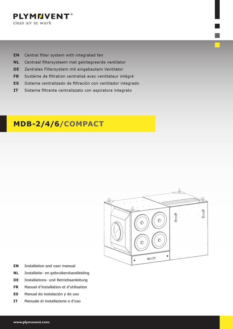
Plymovent SFS User manual

www.plymovent.com
EN Self-cleaningstationaryweldingfumelter
NL Zelfreinigendstationairlasrooklter
DE SelbstreinigenderstationärerSchweißrauchlter
FR Filtre autonettoyant stationnaire de fumées de soudure
EN User manual
NL Gebruikershandleiding
DE Betriebsanleitung
FR Manuel opérateur
SFS

0507320010/061112/D SFS 1
EN – ORIGINAL INSTRUCTION
All rights reserved. The information given in this document has been collected for the general convenience of our clients. It has been
based on general data pertaining to construction material properties and working methods known to us at the time of issue of the
document and is therefore subject at any time to change or amendment and the right to change or amend is hereby expressly
reserved. The instructions in this publication only serve as a guideline for installation, use, maintenance and repair of the product
mentioned on the cover page of this document. This publication is to be used for the standard model of the product of the type given
on the cover page. Thus the manufacturer cannot be held responsible for any damage resulting from the application of this
publication to the version actually delivered to you. This publication has been written with great care. However, the manufacturer
cannot be held responsible, either for any errors occurring in this publication or for their consequences.
NL –VERTALING VAN DE OORSPRONKELIJKE GEBRUIKSAANWIJZING
Alle rechten voorbehouden. De in deze handleiding verstrekte informatie is gebaseerd op algemene gegevens aangaande de ons ten
tijde van verschijnen bekende constructies, materiaaleigenschappen en werkmethoden, zodat wijzingen worden voorbehouden. Om
deze reden dienen de gegeven instructies slechts als richtlijn voor het installeren, gebruiken, onderhouden en repareren van het op
de voorzijde van dit document vermelde product. Deze handleiding is geldig voor het product in de standaard uitvoering. De
fabrikant kan derhalve niet aansprakelijk worden gesteld voor eventuele schade voortvloeiend uit de van de standaard uitvoering
afwijkendespecicatiesvanhetaanugeleverdeproduct.Dezehandleidingismetallemogelijkezorgsamengesteld,maarde
fabrikant kan geen verantwoording op zich nemen voor eventuele fouten in deze handleiding of voor de gevolgen daarvan.
DE – ÜBERSETZUNG DER ORIGINALBETRIEBSANLEITUNG
Alle Rechte vorbehalten. Die in dieser Anleitung enthaltenen Informationen basieren auf allgemeinen Daten bezüglich der
Konstruktion, der Materialeigenschaften und der Arbeitsmethoden, die uns zur Zeit der Veröffentlichung bekannt waren; Änderungen
werden somit vorbehalten. Aus diesem Grunde dienen die gegebenen Vorschriften nur als Leitfaden für das Installieren, Benutzen,
Warten und Reparieren des auf der Vorderseite dieser Anleitung angegebenen Produktes. Diese Ausgabe gilt für die
Standardausführung des Produktes. Der Hersteller haftet daher nicht für eventuelle Schäden, die sich aus der Anwendung dieser
Ausgabe auf Ihr von der Standardausführung abweichendes Produkt ergeben. Diese Ausgabe wurde mit größter Sorgfalt
zusammengestellt. Der Hersteller haftet jedoch nicht für eventuelle Fehler in dieser Ausgabe oder für daraus resultierende Folgen.
FR – TRADUCTION DE LA NOTICE ORIGINALE
Tous droits réservés. Le présent manuel a été mis au point à partir de données relatives à la construction, aux caractéristiques des
matériaux et aux méthodes de production dont nous étions au courant à la parution du manuel. Le manuel est donc sujet à
modicationàtoutmomentetnousnousréservonsexplicitementledroitàunetellemodication.Pourlamêmeraison,cemanuel
servirasimplementdeguideàl’installation,l’emploi,l’entretienetlaréparationduproduitgurantenpremièrepagedecouverture
decedocument.Leprésentmanuels’appliqueaumodèlestandardduproduit.Parconséquent,lefabricantn’estpasresponsable
pourlesdommageséventuelsdécoulantdel’applicationdecedocumentauxmodèlesnonstandarddesproduitslivrés.Nousavons
apporté tous nos soins à la rédaction de ce manuel, mais le fabricant ne peut pas accepter la responsabilité pour les erreurs
éventuelles ni pour les dommages qui en découlent.

0507320010/061112/D SFS 2
ENGLISH Page NEDERLANDS Pag. DEUTSCH Seite
Preface 3 Voorwoord 11 Vorwort 20
1 Safety 3 1 Veiligheid 11 1 Sicherheitsvorschriften 20
2Technicalspecications 42Technischespecicaties 12 2 Technische daten 21
3 General description 5 3 Algemene beschrijving 13 3 Allgemeine Beschreibung 22
4 Installation 6 4 Installatie 14 4 Installation 23
5 Use 7 5 Gebruik 16 5 Betrieb 25
6 Maintenance 8 6 Onderhoud 16 6 Wartung 25
7 Troubleshooting 9 7 Verhelpen van storingen 18 7 Fehlerbehebung 27
8 Spare parts 10 8 Reserveonderdelen 19 8 Ersatzteile 28
9 Disposal 10 9 Afdanken 19 9 Entsorgung 28
CE declaration 10 CE verklaring 19 EG Konformitätserklärung 28
FRANÇAIS Page
Avant-propos 29
1 Instructions de sécurité 29
2Spécicationstechniques 30
3 Description générale 31
4 Installation 32
5 Utilisation 34
6 Entretien 35
7 Reparation des pannes 36
8Piècesdétachées 37
9 Mettre au rancart 37
Déclaration de Conformité 37
TABLE OF CONTENTS

0507320010/061112/D SFS EN - 3
PREFACE
Using this manual
This manual is intended to be used as a work of reference for
professional, well-trained and authorised users to be able to
safely install, use, maintain and repair the product mentioned
on the cover of this document.
Pictograms and symbols
The following pictograms and symbols are used in this
manual:
Suggestions and recommendations to simplify
carrying out tasks and actions.
CAUTION!
Procedures which, if not carried out with the
necessary caution, may damage the product, the
workshop or the environment.
WARNING
Procedures which, if not carried out with the
necessary caution, may damage the product or
cause serious personal injury.
WARNING
Firehazard!Neverusetheproductforltering
inammable,glowingorburningparticlesorsolids
orliquids.Neverusetheproductforltering
aggressive fumes (such as hydrochloric acid) or
sharp particles.
WARNING
Denotes risk of electric shock.
Service and technical support
Forinformationaboutspecicadjustments,maintenanceor
repair jobs which are not dealt with in this manual, please
contact the supplier of the product. Make sure you have the
followingspecicationsathand:
- product name
- serial number
Thesedatacanbefoundontheidenticationplate.
1 SAFETY
General
The manufacturer does not accept any liability for damage to
the product or personal injury caused by non-observance of
the safety instructions in this manual, or by negligence during
installation, use, maintenance and repair of the product
mentioned on the cover of this document and any
corresponding accessories.
Specicworkingconditionsorusedaccessoriesmayrequire
additional safety instructions. Immediately contact your
supplier if you detect a potential danger when using the
product.
The user of the product is always fully responsible for
observing the local safety instructions and regulations.
Observe all safety instructions and regulations which
apply to handling welding equipment.
User manual
- Everyone working on or with the product must be familiar
with the contents of this manual and must strictly observe
the instructions therein. The management should instruct the
personnel in accordance with the manual and observe all
instructions and directions given.
- Neverchangetheorderofthestepstoperform.
- Always keep the manual with the product.
Pictograms and instructions on the product
(if present)
- The pictograms, warnings and instructions attached to the
product are part of the safety features. They must not be
covered or removed and must be present and legible during
the entire life of the product.
- Immediately replace or repair damaged or illegible
pictograms, warnings and instructions.
Users
The use of this product is exclusively reserved to authorised,
well-trainedandqualiedusers.Temporarypersonneland
personnel in training can only use the product under
supervision and responsibility of skilled engineers.
Intended use1
The product has been designed exclusively for harmful fumes
and gases which are released during the most common
welding processes, with the strict restriction that these fumes
and gases can only be supplied through one extraction arm,
while using one extraction fan (FAN-28). Using the product for
other purposes is considered contrary to its intended use. The
manufacturer accepts no liability for any damage or injury
resulting from such use. The product has been built in
accordance with state-of-the-art standards and recognised
safety regulations. Only use the product in technically perfect
condition in accordance with its intended use and the
instructions laid down in the user manual.
Technical specications
Thespecicationsgiveninthismanualmustnotbealtered.
Safety features
- All safety features must be correctly mounted and can only
be removed for maintenance and repair jobs by skilled and
authorised service engineers.
- The product must not be used if the safety features are not
or only partly present, or defective.
- The safety features should be regularly checked for their
proper functioning, and if required, be immediately repaired.
Modications
Modicationof(partsof)theproductisnotallowed.
Use
WARNING
Firehazard!Neverusetheproductforltering
inammable,glowingorburningparticlesorsolids
orliquids.Neverusetheproductforltering
aggressive fumes (such as hydrochloric acid) or
sharp particles.
- Inspect the product and check it for damage. Verify the
functioning of the safety features.
- Check the working environment. Do not allow unauthorised
persons to enter the working environment.
- Use common sense. Stay alert and keep your attention to
your work. Do not use the product when your are tired or
undertheinuenceofdrugs,alcoholormedicine.
- Makesuretheroomisalwayssufcientlyventilated,this
appliesespeciallytoconnedspaces.
- Neverinstalltheproductinfrontofentrancesandexits
which must be used by emergency services.
- Makesurethattheworkshopcontainssufcientapproved
reextinguishers.
- Protect the product against water and humidity.
1. “Intendeduse”aslaiddowninEN-ISO12100istheuseforwhichthetechnical
productissuitedasspeciedbythemanufacturer-inclusiveofhisdirectionsin
the sales brochure. In case of doubt it is the use which can be deducted from
the construction, the model and the function of the technical product which is
considered normal use. Operating the machine within the limits of its intended
use also involves observing the instructions in the user manual.

0507320010/061112/D SFS EN - 4
- Theself-cleaningweldingfumelterfunctionsonlyifthe
harmful fumes and particles are blown directly through an
extractionfanintothelter.Therefore,neverconnectthe
SFS to the suction opening of the extraction fan.
- The SFS must only be connected to the recommended
junction box (CB).
- Theself-cleaningweldingfumelterhasbeendesignedtobe
usedinacongurationwithonlyone extraction arm and
one extraction fan (FAN-28).NeverconnecttheSFS to more
than one extraction arm or extraction fan.
- Air containing particles such as chromium, nickel, beryllium,
cadmium, lead, etc., which is a health hazard, should never
be recycled.
- Theproductmaybeusedforextractingand/orltering
fumes and gases which are released during the following
welding processes:
- MIG/MAG solid wire (GMAW);
- MIG/MAGuxcoredwire(FCAW);
- stick welding (MMA or SMAW);
- TIG (GTAW) welding;
- autogeneous welding.
- Neverusetheproductforextractingdustparticleswhichare
released when welding surfaces treated with primer.
- Neverusetheproductforextractingand/orlteringfumes
and gases which are released during the following (welding)
processes:
- arc-air gouging;
- oil mist;
- paint mist;
- heavy oil mist in welding fumes;
- hot gases (more than 40°C/104°F continuously);
- aggressive fumes (such as acids);
- plasma cutting;
- grinding aluminium and magnesium;
- amecutting;
- extraction of cement, saw dust, wood dust, etc.;
- sucking cigarettes, cigars, oiled tissues and other burning
particles, objects and acids;
- in all situations where explosions can occur.
(This list is not a limited list.)
- Neverswitchontheproductwithoutprelterboxandlter.
- Wait approximately 10 seconds after switching off the motor
oftheconnectedextractionfanbeforedismountingthelter.
Service, maintenance and repairs
This manual clearly makes a distinction between
service maintenance and repair jobs which have to
be carried out by the user and those which have to
be exclusively carried out by well-trained and
authorised service engineers.
- Observe the maintenance intervals given in this manual.
Overdue maintenance can lead to high costs for repairs and
revisions and can render the guarantee null and void.
- Always use tools, parts, materials, lubricants and service
techniques which have been approved by the manufacturer.
Neveruseworntoolsanddonotleaveanytoolsinoronthe
product.
- Safety features which have been removed for service,
maintenance or repairs, must be put back immediately after
nishingthesejobsanditmustbecheckedthattheystill
function properly.
- Regularly clean the inside of the housing.
- Replacetheltersintime.
- Empty the dust barrel in time.
- PreventimproperuseoftheltercoveroftheSFS as work
bench or welding table.
2 TECHNICAL SPECIFICATIONS
2.1 Identication of the product
Theidenticationplatecontainsthefollowingdata:
- serial number
- product name
- power
- supply voltage
2.2 General
Netweight 85 kg (187.4 lbs)
Extractionairowrate 1.100 m3/h (647 CFM)
Filter surface 30 m2(325 ft2)
Filter output in accordance
withDIN24185
EU 7-9
Compressed air consumption max. 60 nl/min. (2 SCFM)
(depending on the degree of
saturationofthelter)
TheextractionairowgivenappliestoaFAN-28
connected SFSwithacleanlteranda1m(3.3 ft)
long air duct (Ø 160 mm/6.3 in.). The combination
extraction fan (FAN-28)-weldingfumelter(SFS)
has its limitations with respect to the maximum air
ductsystemtobeconnected.Forthispurposerst
contact your supplier.
2.3 Dimensions
See Fig. 2.1.
mm inch
A 720 28.3
B 670 26.4
C 660 26.0
D 360 14.2
E Ø 160 Ø 6.30
F 920 36.2
G 515 20.3
H Ø 160 Ø 6.30
I 45 1.77
J 175 6.9
K 130 5.12
L Ø 330 Ø 13.0
Fig. 2.1
A
B
C
D
E
F
G
H
I
J
K
L

0507320010/061112/D SFS EN - 5
2.4 Pressure drop
See Fig. 2.2.
Fig. 2.2
A Static pressure (Pa)
B Airow(m3/h)
1 Soiledlter
2 Cleanlter
2.5 Ambient conditions
Min. operating temperature 5°C (41°F)
Max. operating temperature 45°C (113°F)
Max. relative humidity 80%
3 GENERAL DESCRIPTION
3.1 General description
Theproducthasbeenspeciallydesignedforlteringharmful
fumes and gases which are released during the most common
welding processes. For this purpose the SFS is often integrated
incongurationswhichcontainbesidetheweldingfumelter,
an extraction arm, an extraction fan (FAN-28) and an air duct
system.
Theself-cleaningweldingfumelterconsistsofthefollowing
main components (see Fig. 3.1):
Fig. 3.1:
A ltercover
B magnetic valve (24 VAC)
C lterbody
D control panel
E outlet opening (left and right)
F dust barrel
G prelterbox(shownseparately)
H inlet opening (left and right)
I wall mounting bracket
J lter
K cleaning unit with quick air relief valve
A
K
J
I
H
H
E
E
F
B
C
D
Fig. 3.1

0507320010/061112/D SFS EN - 6
3.2 Operation
Thepollutedfumeisblownintotheweldingfumelterbyan
externalextractionfanviaaspiralo-tubeoraexiblehoseand
viatheprelterbox(seeFig.3.1G),wherethelargerparticles
and any sparks are separated.
Subsequentlytheairbythelter(Fig.3.1J)withaltering
surface or approximately 30 m2(325 ft2) in which almost all
particles (from 0,3 µm) are caught.
Via the outlet opening(s) (Fig. 3.1 E) the clean air leaves the
lterandifdesireditcanbereturnedtotheworkshopor
discharged outside.
Whenthelterbecomesheavilysaturated-andconsequently
the extraction capacity strongly reduces - a pressure difference
switch activates the RoboClean compressed air cleaning
mechanismwhichthoroughlycleansthelterusingsections
controlled compressed air charges. The dust and dirt particles
fall in a plastic dust barrel (Fig. 3.1 F) on the outside of the
lter.
4 INSTALLATION
4.1 Unpacking
• Check that the product is complete. The package should
contain:
- weldingfumelter(SFS)
- wall mounting bracket
- supply cable (NCW-11)
- cap nut (PG-7)
- electric diagram
- prelterbox
If parts seem to be missing or damaged, contact your supplier.
4.2 Mounting
CAUTION!
Theself-cleaningweldingfumelterfunctionsonly
if the harmful fumes are blown directly through an
extractionfanintothelter.Therefore,never
connect the SFS to the extraction opening of the
fan.Theself-cleaningweldingfumelterhasbeen
designedtobeusedinacongurationwithonly
one extraction arm and one extraction fan (FAN-
28).NeverconnecttheSFS to more than one
extraction arm or extraction fan. Only connect the
SFS to the CB junction box.
Mount the SFS (Fig. 4.1 C) in such a way that the
inlet opening (Fig. 4.1 B) is horizontally in line with
the outlet opening (Fig. 4.1 D) of the extraction fan.
In the standard set-up the SFS is positioned to the
right of the extraction fan (Fig. 4.1 A). See Fig. 4.2
for the recommended height of the wall mounting
bracket. For mounting the (NMB or TNB) wall
mounting brackets (Fig. 4.1 E) and the extraction
fan, see the corresponding manuals.
CAUTION!
Before mounting the wall mounting bracket
(Fig. 4.2 A) check that the wall is strong enough.
The net weight of the SFS is approx. 85 kg (187
lbs). When drilling holes note any gas, water or
electricity lines. Do not position the SFS where it is
exposed to vibrations or heat radiation from heat
source. Observe the earlier described ambient
conditions.
Fig. 4.1
CB
A
E
D
2600

0507320010/061112/D SFS EN - 7
Fig. 4.2
Fig. 4.3
4.2.1 Installation
• Mount the wall mounting bracket (Fig. 4.2 A). See Fig. 4.2
for the recommended height and the drilling dimensions.
Notethatthemountingheightgivenonlyappliesifthe
extraction arm is mounted at 2,600 mm (102.4 in.) and
the SFS is horizontally in line with the outlet opening of the
extractionfan.Makesurethereissufcientspaceatthe
top(min.700mm[27.6in.]);whenreplacingthelterthe
cover must be removed.
• Position the complete SFS (Fig. 4.3 A) over the wall bracket
(Fig. 4.3 B).
• Subsequently, as desired, mount on the inlet opening of
the SFS:
- aspiralo-tube(Ø160mm[6.3in.]),overtheT-prole;
- aCKS(exibleextractionhose[Ø160mm/6.3in.]with
two hose clamps).
• Saw one or both outlet opening(s) open (they are located
in the recesses of the dust barrel) and, if necessary,
connect the outlet opening(s) to an air duct system.
• Check that the complete extraction system is airtight. If it
is not allowed to recycle the air, connect the outlet opening
to an air duct system which leads the air to the outside.
• Finally, lock the complete unit by inserting two bolts in the
slottedholesinthelterbody;thisisnecessary.
Installation of the prelter box
Toinstalltheprelterbox,refertotheinstructionsheet.
4.2.2 Electric connection
The 24 VAC supply for the SFS is obtained via the CB control
box. For this purpose the supply cable (NCW-11) and the cap
nut (PG-7) are also included. The cap nut must be mounted in
the CB.
• Connect the NCW-11 to the three-pin connection block on
the rear of the SFS and on the CB (see the corresponding
manual).
WARNING
Preventdamage.Notethecolourcodeofthecable
when connecting.
WARNING
Switch OFF the mains supply of the CB before
connecting the NCW-11.
4.2.3 Compressed air connection
The cleaning mechanism functions on compressed air with a
recommended working pressure of 400-500 kPa/4-5 bar (1600
- 2000 in. WG/60 - 75 psi). Always make sure that the
working pressure is between 400-500 kPa/4-5 bar (1600
- 2000 in. WG/60 - 75 psi). Preferably the pressure should be
at 450 kPa/4.5 bar (1800 in. WG/65 psi). If required, mount a
pressure reducing valve to prevent the safety valve from being
actuated.
WARNING
Prevent damage to the cleaning mechanism.
Make sure that the compressed air is free from oil
en moisture.
• Connect the compressed air hose to the cap nut (1/4” int.)
on the rear of the SFS.
5 USE
Fig. 5.1
CAUTION!
Before use carefully read the safety instructions.
Determine based on the local regulations and the
welding process applied whether or not materials
can be recycled.
B A

0507320010/061112/D SFS EN - 8
5.1 Controls
Thecontrolpanelisttedwiththefollowingcontrols
(see Fig. 5.1):
Fig. 4.1:
A Indicator (yellow)
Theindicatorlights(“CLEANING”)indicatingthattheSFS is
busy performing the (self) cleaning process. The indicator
blinks(“ALARM”)indicatingthatthelterissaturatedand
cannot be cleaned. A blinking indicator may also indicate
thatthepressureistoolowtocleanthelter.
B Reset/start button
Black button for manually switching the cleaning
mechanismonandoff(“STARTCLEANING”and“STOP
CLEANING/ALARM”).
5.2 Control
The processes below also apply in combination with WL and
AST (if activated).
5.2.1 Normal operation
During normal operation (i.e. with a clean, non-saturated
lter)theSFS functions fully independently; the welding fumes
which are released during welding activities are blown into the
lterbytheswitched-onextractionfan.Assoonas,asaresult
ofclogging,theminimumairowhasbeenreached,apressure
difference switch activates the RoboClean compressed air
cleaningmechanismwhichsubsequentlycleansthelterusing
section controlled jets of compressed air (3x). The dust and
dirt particles then fall into the dust barrel.
During this (self) cleaning process the indicator lights and
extinguishes after cleaning. The fan keeps turning normally.
5.2.2 Saturation of the system
Iftheltercannotbecleanedagain,aftertenbytheSFS itself
initiated attempts, the indicator starts blinking. However, the
work that is being carried out can continue as the extraction
fan may continue to turn. A blinking indicator usually indicates
asaturatedlter.Alsorefertochapter7.
• Switch off the blinking indicator by pressing the reset/start
button.
• Replacethelterand/oremptythedustbarrel
(see chapter 6).
5.2.3 Manual operation
CAUTION!
AVOIDmanualoperationduringtherst10net
operationhours;ifthishappensthelterefciency
will be reduced.
Using the black reset/start button the cleaning mechanism can
be manually switched on and off. When switching on ("START
CLEANING")theextractionfanis/remainsswitchedonand
lights the indicator continuously during the full cleaning cycle
(approx. 40-50 min. = 40 jets of compressed air).
The cleaning process can be stopped at any moment by
pressingthereset/startbuttonagain(“STOPCLEANING/
ALARM”).
The cleaning mechanism returns to normal operation.
6 MAINTENANCE
The product has been designed to function without problems
for a long time with a minimum of maintenance. In order to
guarantee this, some simple, regular maintenance and
cleaning activities are required which are described in this
chapter. If you observe the necessary caution and carry out
the maintenance at regular intervals, any problems occurring
will be detected and corrected before they lead to a total
standstill.
The indicated maintenance intervals can vary depending on
thespecicworkingandambientconditions.Thereforeitis
recommended to thoroughly inspect the complete product
once every year beside the indicated periodic maintenance.
For this purpose contact your supplier.
WARNING
Overduemaintenancecancausere.
WARNING
Always switch OFF the connected extraction fan
before carrying out the activities below. First read
the maintenance regulations at the beginning of this
manual.
6.1 Periodic maintenance
The maintenance activities in the table below indicated by [1]
can be carried out by the user; other activities are strictly
reserved for well-trained and authorised service engineers.
Action 1-3
months
every 3
months
every 6
months
Checkthesteelmeshlterof
theprelterboxfordamage,
clogging and saturation. If
damaged, clogged or
saturated, refer to section
6.2.2.
X[1]
Clean the inside of the
prelterboxusingan
industrial vacuum cleaner.
X[1]
Clean the outside with a mild
detergent.
X[1]
Clean the inside using an
industrial vacuum cleaner
and remove the dust from
theltercompartment.
X[1]
Checkthelterfordamage,
clogging and saturation.
X[1]
Check the functioning of the
cleaning mechanism via
manual operation (turning,
leakage).
X
Check whether the dust
barrel is full.
X[1]
6.2 Replacing the lter, the steel mesh lter of
the prelter box and/or emptying the dust
barrel
WARNING
Saturatedltersand/orfulldustbarrelsoften
contain dust and particles which at inhalation may
form a health hazard. When replacing them always
wear a high-quality and approved face mask. Wrap
everything in a properly closed plastic bag and
dispose of it in compliance with the local
regulations.

0507320010/061112/D SFS EN - 9
6.2.1 Filter
Replacethelter:
- when damaged;
- whentheextractioncapacityremainsinsufcient;
- when the indicator keeps blinking, with the cleaning
mechanism running.
Youmustlearnfromexperiencewhentoreplacethelter,
sincethelifespanofthelterstronglydependsonthe
composition of the welding fumes, the humidity, etc.
• Removetheltercover(Fig.6.1A)bylooseningthestar
knob and loosening the four clips.
• Removethelter(Fig.6.1B).Itisrecommendedtoclean
theltercompartmentusinganindustrialvacuumcleaner.
• Positionthenewlterandmounttheltercover.
Fig. 6.1
6.2.2 Prelter box
Replacethesteelmeshlter:
- when it is clogged or saturated and cannot be cleaned using
a vacuum cleaner; or
- when it has been damaged.
Incasethesteelmeshlterhasbeendamaged,itis
recommendedtoalsoreplacetheltercartridge.
Toreplacethesteelmeshlter,proceedasfollows:
• Disconnect the extraction fan from the input power.
• Loosenthetwoclipsandremovetheltercover.
• Removethesteelmeshlter.
• If required by federal, state and/or local regulations and
guidelines,concealprelterinappropriatebag,e.g.plastic
bag.
Sparepreltersaresuppliedinaplasticbag.This
bag can be used to pack and dispose of the used
prelter.
• Cleantheinsideoftheprelterboxwithanindustrial
vacuum cleaner.
• Installanewsteelmeshlter.
• Replacetheltercoverandfastenthetwoclips.
6.2.3 Dust barrel
Empty the dust barrel (Fig. 6.2):
- when full;
- (preferably)uponreplacementofthelter.
Fig. 6.2
7 TROUBLESHOOTING
• If the machine does not function (correctly), consult the
checklist below to see if you can remedy the error yourself.
Should this not be possible, contact your supplier.
WARNING
Always switch OFF the connected extraction fan
before carrying out the activities below. First read
the maintenance regulations at the beginning of this
manual.
A number of problems in the checklist below can
also be caused by defects in the connected
equipment. This manual only deals with problems
and solutions directly related to the product itself.
Problem Cause Solution
Extraction remains
insufcient.
Incorrect direction of
rotation of extraction
fan.
Change the directions
of rotation. See the
corresponding manual.
Filter clogged or
saturated.
Replacelter.
Steelmeshlter
insideprelterbox
clogged.
Clean (see section 6.1)
or replace (see section
6.2.2) the steel mesh
lter.
Cleaning mechanism
defective.
Repair cleaning
mechanism.
Dust or smoke from
outlet opening.
Filter ripped or
placed incorrectly.
Replacelterorplaceit
correctly.
Dust or smoke from
inlet opening.
Outlet(s) blocked. Remove obstructions
from the outlet
opening(s) and/or
connected ductwork.
Filter cartridge
clogged.
Replaceltercartridge
(see section 6.2.1).
Steelmeshlter
insideprelterbox
clogged.
Clean (see section 6.1)
or replace (see section
6.2.2) the steel mesh.
Dust or smoke from
dust barrel.
Sealing of dust
barrel leaky.
Replace sealing of dust
barrel.

0507320010/061112/D SFS EN - 10
Problem Cause Solution
Indicator
extinguished.
Indicator defective. Replace indicator.
Control PCB
defective.
Replace control PCB.
24 VAC supply
defective.
Remedy the 24 VAC
supply.
Indicator keeps
blinking.
Filter saturated. Replace.
See chapter 6.
Cleaning mechanism defective:
- 24 VAC magnetic
valve defective.
Replace magnetic coil
or the diaphragm.
- Control PCB
defective.
Replace PCB.
- Cleaning
mechanism
defective or worn.
Replace the cleaning
mechanism.
- Nocompressedair
or compressed air
pressure too low.
Check the compressed
air system and/or the
compressed air
connection.
- Pressure difference
switch defective.
Replace the pressure
difference switch.
SFS does not react
to pressing the
reset/start button.
Reset/start button
defective.
Replace reset/start
button.
Control PCB
defective.
Replace control PCB.
24 VAC supply
defective.
Remedy the 24 VAC
supply.
8 SPARE PARTS
The following spare parts are available for the product (refer to
Fig. I on page 38).
• Address your order to your supplier and always state the
data below:
- product name, supply voltage and serial number
(seetheidenticationplate);
- article number of the particular part;
- description;
- quantity.
Art. no. Description
0042000040 Membrane valve
0046030010 Pressure relief valve 6-10 bar
0324150120 Control lamp 28V, yellow
0326701020 PC board control MFS/SFS
0328290010 Reset/start button
0401102030 Sealing ring
0690150070 Lock SFD/SFS
0806010160 Handle barrel SFS
0806014020 Cover star knob M8
0809040040 Cover Ø 160 mm
0810100050 Sealing membrane valve
9822010010 Sealing SFD/SFS (2,5 m)
9824000030 Pressure difference switch SFS (670 Pa)
9824000090 Piston mechanism MFS/SFS/SCS
9850060110 DuraFilter FCC-30
9850060120 Barrel15LforlterresidueSFS (reusable)
0102080100 Spark arrester MFS/SFS (HD) (not shown)
9 DISPOSAL
After life of the product, dispose it of in accordance with
federal, state or local regulations.
CE DECLARATION
CE declaration of conformity for machinery
We, Plymovent Manufacturing B.V., Wezelkoog 11, 1822 BL
Alkmaar,theNetherlands,herewithdeclare,onourown
responsibility, that the product(s):
- SFS
which this declaration refers to, is/are in accordance with the
conditions of the following Directives:
- Machine Directive 2006/42 EC
- EMC 2004/108 EC
and is/are in conformity with the following harmonized
standard(s) and/or other such normative documents +
amendments, if any:
- EN-ISO12100:2010(safetyofmachinery)
- EN-ISO13857:2008(safetydistances)
- EN-IEC60204-1:2006(electricalsafety)
Alkmaar,theNetherlands,6November2012
Ir. F. Coehoorn
Vice President Research & Development
Aninstallationisdenedasacombinationofseveralnished
products or components that are assembled by an installer at
a given place. The various parts of the installation are intended
to operate together in a particular environment and to perform
aspecictask.Theentireinstallationmustcomplywiththe
relevant directives and standards. The assembly instructions
given by the manufacturer, as well as the whole method of
installation, must be in accordance with good engineering
practices within the context of installations, as well as
installation rules. Considering the above, the installer will be
responsibleforcompletingtheinstallationandissuingthenal
CE Declaration of Conformity.

0507320010/061112/D SFS NL - 11
VOORWOORD
Gebruik van de handleiding
Deze handleiding is bedoeld als naslagwerk waarmee
professionele, geschoolde en daartoe bevoegde gebruikers het
aan de voorzijde van dit document vermelde product op veilige
wijze kunnen installeren, gebruiken, onderhouden en
repareren.
Pictogrammen en symbolen
In deze handleiding worden de volgende pictogrammen en
symbolen gebruikt:
Suggesties en adviezen om de betreffende taken of
handelingen gemakkelijker te kunnen uitvoeren.
VOORZICHTIG!
Procedures die -wanneer ze niet met de nodige
voorzichtigheid worden uitgevoerd- schade aan het
product, de omgeving of het milieu tot gevolg
kunnen hebben.
WAARSCHUWING
Procedures die -wanneer ze niet met de nodige
voorzichtigheid worden uitgevoerd- ernstige schade
aan het product of lichamelijk letsel tot gevolg
kunnen hebben.
WAARSCHUWING
Brandgevaar! Gebruik het product nooit voor het
afzuigen van brandbare, gloeiende of brandende
deeltjes of (vloei)stoffen. Gebruik het product nooit
voorhetafzuigenen/oflterenvanagressieve
dampen (zoals zoutzuur) of scherpe deeltjes.
WAARSCHUWING
Gevaar voor elektrische spanning.
Service en ondersteuning
Voorinformatiebetreffendespeciekeafstellingen,
onderhouds- of reparatiewerkzaamheden die buiten het bestek
van deze handleiding vallen, gelieve contact op te nemen met
de leverancier van het product. Deze is altijd bereid u te
helpen. Zorg ervoor dat u de volgende gegevens bij de hand
heeft:
- productnaam
- serienummer
Dezegegevensvindtuophetidenticatieplaatje.
1 VEILIGHEID
Algemeen
De fabrikant aanvaardt geen enkele aansprakelijkheid voor
schade of letsel veroorzaakt door het niet (strikt) naleven van
de veiligheidsvoorschriften en -instructies in deze handleiding,
dan wel door onachtzaamheid tijdens installatie, gebruik,
onderhoud en reparatie van het op de voorzijde van dit
document vermelde product en de eventuele bijbehorende
accessoires.
Afhankelijkvandespeciekewerkomstandighedenof
gebruikte accessoires kunnen aanvullende
veiligheidsinstructiesnodigzijn.Neems.v.p.directcontactop
met uw leverancier indien u bij het gebruik van het product
een potentieel gevaar hebt geconstateerd.
De gebruiker van het product is te allen tijde volledig
verantwoordelijk voor de naleving van de plaatselijk
geldende veiligheidsvoorschriften en -richtlijnen.
Respecteer alle veiligheidsvoorschriften en -richtlijnen
die van toepassing zijn bij het omgaan met
lasapparatuur.
Gebruikershandleiding
- Een ieder die aan of met het product werkt, dient van de
inhoud van deze handleiding op de hoogte te zijn en de
instructies daarin nauwgezet op te volgen. De bedrijfsleiding
dient het personeel aan de hand van de handleiding te
onderrichten en alle voorschriften en aanwijzingen in acht te
nemen.
- Wijzig nooit de volgorde van de te verrichten handelingen.
- Bewaar de handleiding steeds in de nabijheid van het
product.
Pictogrammen en instructies op het product
(indien aanwezig)
- Op het product aangebrachte pictogrammen,
waarschuwingen en instructies maken deel uit van de
getroffen veiligheidsvoorzieningen. Ze mogen niet worden
afgedekt of verwijderd en dienen gedurende de gehele
levensduur van het product aanwezig en leesbaar te zijn.
- Vervang of herstel onmiddellijk onleesbaar geworden of
beschadigde pictogrammen, waarschuwingen en instructies.
Gebruikers
Gebruik van het product is uitsluitend voorbehouden aan
daartoe opgeleide en bevoegde gebruikers. Tijdelijke
werkkrachten en personen in opleiding mogen het product
uitsluitend onder toezicht en verantwoording van vaklui
gebruiken.
Gebruik volgens bestemming1
Hetproductisuitsluitendontworpenvoorhetlterenvan
schadelijke rook en stoffen die vrijkomen bij de meest
voorkomende lasprocessen, met de nadrukkelijke restrictie dat
deze rook en stoffen slechts door een afzuigarm -en met
gebruikmaking van een afzuigventilator (FAN-28)- mogen
worden toegevoerd. Elk ander of verdergaand gebruik geldt
niet als conform de bestemming. Voor schade of letsel dat
hiervan het gevolg is, aanvaardt de fabrikant geen enkele
aansprakelijkheid. Het product is in overeenstemming met de
vigerende normen en richtlijnen. Gebruik het product
uitsluitend in technisch perfecte conditie, conform de
hierboven beschreven bestemming.
Technische specicaties
Deindezehandleidingvermeldespecicatiesmogenniet
worden gewijzigd.
Veiligheidsvoorzieningen
- Alle veiligheidsvoorzieningen moeten correct zijn gemonteerd
en mogen uitsluitend voor onderhouds- en
reparatiewerkzaamheden worden verwijderd door daartoe
opgeleide, bevoegde service-technici.
- Het product mag nooit worden gebruikt indien de
veiligheidsvoorzieningen niet compleet of niet aanwezig zijn,
dan wel buiten werking zijn gesteld of geraakt.
- De veiligheidsvoorzieningen moeten regelmatig op correcte
werking worden gecontroleerd en, indien nodig, onmiddellijk
worden gerepareerd.
Modicaties
Modicatievan(onderdelenvan)hetproductisniet
toegestaan.
1. Het“Gebruikvolgensbestemming”zoalsvastgelegdindeEN-ISO12100ishet
gebruik waarvoor het technisch product volgens de opgave van de fabrikant
-inclusief diens aanwijzingen in de verkoopbrochure- geschikt is. Bij twijfel is
dat het gebruik dat uit de constructie, uitvoering en functie van het product als
gebruikelijk naar voren komt. Tot het gebruik volgens bestemming behoort ook
het in acht nemen van de instructies in de gebruikershandleiding.

0507320010/061112/D SFS NL - 12
Gebruik
WAARSCHUWING
Brandgevaar! Gebruik het product nooit voor het
lterenvanbrandbare,gloeiendeofbrandende
deeltjes of (vloei)stoffen. Gebruik het product nooit
voorhetlterenvanagressievedampen(zoals
zoutzuur) of scherpe deeltjes.
- Inspecteer het product en controleer het op beschadigingen.
Verieerdewerkingvandeveiligheidsvoorzieningen.
- Controleer de werkomgeving. Laat onbevoegden niet in de
werkomgeving toe.
- Gebruik uw gezond verstand. Blijf voortdurend opletten en
houd uw aandacht bij het werk. Gebruik het product niet als
u vermoeid bent of onder invloed verkeert van drugs, alcohol
of medicijnen.
- Zorg altijd voor voldoende ventilatie, met name in kleinere
ruimten.
- Installeer het product nooit voor in-, uit- en doorgangen die
zijn bedoeld voor hulpdiensten.
- Zorg ervoor dat op de werkplek voldoende goedgekeurde
brandblussers aanwezig zijn.
- Bescherm het product tegen water of vocht.
- Hetzelfreinigendelasrooklterwerktuitsluitendindiende
schadelijke rook en stoffen door een afzuigventilator in het
lterwordengeblazen.SluitdeSFS dan ook nooit aan op de
aanzuigopening van de afzuigventilator.
- Sluit de SFS uitsluitend aan op de aanbevolen aansluitkast
(CB).
- Hetzelfreinigendelasrooklterisontworpenomteworden
gebruiktineenconguratiemetslechtséén afzuigarm en
één afzuigventilator (FAN-28). Sluit de SFS dan ook nooit
aan op meerdere afzuigarmen of meerdere
afzuigventilatoren.
- Lucht die deeltjes bevat die een bedreiging vormen voor de
gezondheid -zoals chroom, nikkel, beryllium, cadmium, lood,
etc.- mag nooit worden gerecycleerd. Deze lucht moet altijd
buiten de werkruimte worden gebracht.
- Hetproductisgeschiktvoorhetafzuigenen/oflterenvan
dampen die ontstaan tijdens de volgende lasprocessen:
- MIG/MAG massief draad (GMAW);
- MIG/MAG gevulde draad (FCAW);
- elektrisch lassen (MMA of SMAW);
- TIG (GTAW) lassen;
- autogeen lassen.
- Gebruik het product nooit voor het afzuigen van stofdeeltjes
die vrij komen bij laswerkzaamheden aan geprimerde
oppervlakken.
- Gebruikhetproductnooitvoorhetafzuigenen/oflteren
van dampen van, of tijdens:
- gutsen;
- olienevels;
- vernevels;
- zware olienevels in lasdampen;
- hete gassen (continu boven 40°C);
- agressieve gassen (zoals van zuren);
- plasma snijden;
- aluminium of magnesium slijpsel;
- vlamspuiten;
- cement, zaagsel of houtstof e.d.;
- brandende sigaretten, sigaren, olie doeken en andere
brandende deeltjes, voorwerpen en zuren;
- in alle explosiegevaarlijke situaties.
(Deze lijst is niet allesomvattend.)
- Schakelhetproductnooitzondervoorlterboxenlterin.
- Wacht na het uitschakelen van de motor circa 10 seconden
alvorenshetltertedemonteren.
Service, onderhoud en reparaties
In deze handleiding wordt een duidelijk onderscheid
gemaakt in service-, onderhouds- en
reparatiewerkzaamheden die door de gebruiker
mogen worden verricht, en die welke uitsluitend zijn
voorbehouden aan daartoe opgeleide en bevoegde
service-technici.
- Respecteer de in deze handleiding gegeven
onderhoudsintervallen. Achterstallig onderhoud kan leiden
tot hoge kosten voor reparaties en revisies en kan
aanspraken op garantie doen vervallen.
- Gebruik altijd door de fabrikant goedgekeurde
gereedschappen, onderdelen, materialen, smeermiddelen en
service-technieken. Gebruik nooit versleten gereedschap en
laat geen gereedschap in of op het product achter.
- Veiligheidsvoorzieningen die ten behoeve van service,
onderhoud of reparatie zijn verwijderd, moeten na deze
werkzaamheden onmiddellijk worden gemonteerd en op
correct functioneren worden gecontroleerd.
- Reinig regelmatig de binnenkant van de behuizing.
- Vervangdelterstijdig.
- Leeg tijdig het stofvat.
- Voorkomoneigenlijkgebruikvandelterkapalswerkbankof
lastafel.
2 TECHNISCHE SPECIFICATIES
2.1 Identicatie van het product
Hetidenticatieplaatjebevatdevolgendegegevens:
- serienummer
- productnaam
- vermogen
- aansluitspanning
2.2 Algemeen
Nettogewicht 85 kg
Afzuigdebiet 1.100 m3/h
Filteroppervlak 30 m2
Filterrendement volgens
DIN24185
EU 7-9
Persluchtverbruik max. 60 nl/min. (afhankelijk van
vervuilingsgraadvanhetlter)
Het vermelde afzuigdebiet geldt voor een op een
FAN-28 aangesloten SFSmeteenschoonlteren
een luchtkanaal van 1 m lengte (Ø 160 mm). De
combinatie afzuigventilator (FAN-28)-lasrooklter
(SFS) kent beperkingen met betrekking tot het
maximaalaantesluitenluchtkanaalsysteem.Neem
hiertoe eerst contact op met de leverancier.

0507320010/061112/D SFS NL - 13
2.3 Afmetingen
Zie Fig. 2.1.
mm
A 720
B 670
C 660
D 360
E Ø 160
F 920
G 515
H Ø 160
I 45
J 175
K 130
L Ø 330
Fig. 2.1
2.4 Drukval
Zie Fig. 2.2.
Fig. 2.2
A Statische druk (Pa)
B Luchtstroom (m3/h)
1 Vervuildlter
2 Schoonlter
2.5 Omgevingscondities
Min. bedrijfstemperatuur 5°C
Max. bedrijfstemperatuur 45°C
Max. relatieve vochtigheid 80%
3 ALGEMENE BESCHRIJVING
3.1 Algemene beschrijving
Hetproductisspeciaalontworpenvoorhetlterenvan
schadelijke rook en stoffen die vrijkomen bij de meest
voorkomende lasprocessen. De SFS wordt daartoe veelal
geïntegreerdinconguratiesdie,naasthetlasrooklter,een
afzuigarm, een afzuigventilator (FAN-28) en een
luchtkanaalsysteem omvatten.
Hetzelfreinigendelasrooklterbestaatuitdevolgende
hoofdcomponenten (zie Fig. 3.1):
Fig. 3.1:
A lterkap
B magneetklep (24 VAC)
C lterbody
D bedieningspaneel
E uitblaasopening (links en rechts)
F stofvat
G voorlterbox(afzonderlijkafgebeeld)
H inblaasopening (links en rechts)
I wandbevestigingsbeugel
J lter
K reinigingsunit met snelontluchtventiel
3.2 Werking
Devervuilderookwordtinhetlasrookltergeblazendooreen
externeafzuigventilatorviaeenspiraalbuisofeenexibele
slangenviadevoorlterbox(zieFig.3.1G),waarbijde
grotere deeltjes en vonken worden afgescheiden.
Vervolgenswordtdeluchtdoorhetlter(zieFig.3.1J)met
eenlteroppervlakvancirca30m2gezuiverd waarbij
nagenoeg alle deeltjes (vanaf 0,3 µm) worden afgevangen.
Via de uitblaasopening(en) (zie Fig. 3.1 E) verlaat de
gereinigdeluchthetlterenkannaarkeuzenaardewerkplek
of naar buiten worden gevoerd.
Ophetmomentdathetlterzwaarvervuildraakt-en
dientengevolge de afzuigcapaciteit sterk afneemt-, activeert
een drukverschilschakelaar het RoboClean perslucht-
reinigingsmechanisme dat vervolgens met behulp van
sectiegestuurdepersluchtstotenhetltergrondigreinigt.
Destof-envuildeeltjesvallenaandebuitenzijdevanhetlter
in een kunststof stofvat (zie Fig. 3.1 F).
A
B
C
D
E
F
G
H
I
J
K
L

0507320010/061112/D SFS NL - 14
Fig. 3.1
A
K
J
I
H
H
E
E
F
B
C
D
4 INSTALLATIE
4.1 Uitpakken
• Controleer of het product compleet is. De inhoud van de
verpakking bestaat uit:
- lasrooklter(SFS)
- wandbevestigingsbeugel
- voedingskabel (NCW-11)
- aansluitwartel (PG-7)
- elektrisch schema
- voorlterbox
Indien onderdelen ontbreken of beschadigd zijn, neem dan
contact op met uw leverancier.
4.2 Montage
VOORZICHTIG!
Hetzelfreinigendelasrooklterwerktuitsluitend
indien de schadelijke rook en stoffen door de
afzuigventilatorinhetlterwordengeblazen. Sluit
de SFS dan ook nooit aan op de aanzuigopening van
deafzuigventilator.Hetlasrooklterisontworpen
omtewordengebruiktineenconguratiemetéén
afzuigarm en één afzuigventilator (FAN-28). Sluit
de SFS dan ook nooit aan op meerdere afzuigarmen
of meerdere afzuigventilatoren. Sluit de SFS
uitsluitend aan op de CB aansluitkast.
Monteer de SFS (Fig. 4.1 C) zodanig dat de
inblaasopening (Fig. 4.1 B) horizontaal in één lijn
ligt met de uitblaasopening (Fig. 4.1 D) van de
afzuigventilator. In de standaardopstelling wordt de
SFS rechts van de afzuigventilator (Fig. 4.1 A)
geplaatst. Zie Fig. 4.2 voor de advieshoogte van de
wandbevestigingsbeugel. Voor montage van de
(NMB of TNB) wandbevestigingsbeugels (Fig. 4.1 E)
en de afzuigventilator, zie de betreffende
handleidingen.
VOORZICHTIG!
Controleer -alvorens de wandbevestigingsbeugel
(Fig. 4.2 A) te monteren- of de muur sterk genoeg
is. Het nettogewicht van de SFS is ca. 85 kg. Let bij
het boren op eventueel aanwezige gas-, water- en
elektriciteitsleidingen. Plaats de SFS niet op
plaatsen waar deze is blootgesteld aan trillingen of
aan warmtestraling afkomstig van warmtebronnen.
Respecteer de eerder vermelde omgevingscondities.

0507320010/061112/D SFS NL - 15
Fig. 4.1
Fig. 4.2
Fig. 4.3
4.2.1 Installatie
• Monteer de wandbevestigingsbeugel (Fig. 4.2 A).
Zie Fig. 4.2 voor de advieshoogte en de boormaten. De
aangegeven advieshoogte is van toepassing indien de
afzuigarm op 2.600 mm wordt gemonteerd en de SFS
horizontaal in één lijn ligt met de uitblaasopening van de
afzuigventilator. Zorg voor voldoende ruimte (min. 700
mm)aandebovenzijde;bijhetvervangenvanhetlter
moetimmersdelterkapwordengedemonteerd.
• Plaats de complete SFS (Fig. 4.3 A) over de wandbeugel
(Fig. 4.3 B).
• Monteer vervolgens naar keuze op de inblaasopening van
de SFS:
- eenspiralo-buis(Ø160mm),overhetT-proel;
- eenCKS(exibeleafzuigslang[Ø160mm]mettwee
slangklemmen).
• Zaag één of beide uitblaasopening(en) open (te vinden in
de uitsparingen van het stofvat) en sluit de
uitblaasopening(en) eventueel aan op een kanaalsysteem.
• Controleer of het gehele afzuigsysteem luchtdicht is. Indien
niet mag worden gerecycleerd, sluit dan de
uitblaasopening(en) altijd aan op een kanaalsysteem dat
de lucht naar buiten voert.
• Borg tenslotte de gehele unit met bijvoorbeeld twee
fretbouten in de sleufvormige uitsparingen van de
lterbody;ditisnoodzakelijk.
Installatie van de voorlterbox
Raadpleeg het instructieblad voor installatie van de
voorlterbox.
4.2.2 Elektrische aansluiting
De 24 VAC voeding voor de SFS wordt verkregen via de CB
aansluitkast. Hiertoe worden een voedingskabel (NCW-11) en
PG-7 wartel meegeleverd. De wartel moet in de CB worden
gemonteerd.
• Sluit de NCW-11 aan op het driepolige aansluitblok aan de
achterzijde van de SFS en op de CB (zie de betreffende
handleiding).
WAARSCHUWING
Voorkom schade. Let bij het aansluiten van de kabel
op de kleurcodes.
CB
A
E
D
2600
B A

0507320010/061112/D SFS NL - 16
WAARSCHUWING
Schakel de netvoeding van de CB UIT alvorens de
NCW-11 aan te sluiten.
4.2.3 Persluchtaansluiting
Het reinigingsmechanisme werkt op perslucht met een
aanbevolen werkdruk van 400-500 kPa (4-5 bar). Zorg er
altijd voor dat de werkdruk tussen 400-500 kPa (4-5 bar) ligt.
Bij voorkeur moet de druk op 450 kPa (4,5 bar) liggen.
Monteer indien nodig een reduceerventiel om te voorkomen
dat het veiligheidsventiel in werking treedt.
WAARSCHUWING
Voorkom schade aan het reinigingsmechanisme.
Zorg ervoor dat de perslucht vrij is van olie en
vocht.
• Sluit de persluchtslang aan op de aansluitwartel (1/4" inw.)
aan de achterzijde van de SFS.
5 GEBRUIK
Fig. 5.1
VOORZICHTIG!
Neemvóórgebruikdeveiligheidsvoorschriften
zorgvuldig door. Bepaal aan de hand van de
plaatselijk geldende voorschriften en het gebruikte
lasproces of er al dan niet wordt gerecycleerd.
5.1 Bedieningsorganen
Het bedieningspaneel is voorzien van de volgende
bedieningsorganen (zie Fig. 5.1):
Fig. 4.1:
A Signaallamp (geel)
Designaallamplichtop(“CLEANING”)tentekendatde
SFS bezig is met het (zelf)reinigingsproces. De signaallamp
knippert(“ALARM”)tentekendathetlterisverzadigden
niet kan worden gereinigd, dan wel dat de druk niet
toereikendisomhetltertereinigen.
B Reset-/startknop
Zwarte knop voor het handmatig in- en uitschakelen van
hetreinigingsmechanisme(resp.“STARTCLEANING”en
“STOPCLEANING/ALARM”).
5.2 Bediening
Onderstaande processen zijn ook van toepassing in combinatie
met een WL en AST (indien geactiveerd).
5.2.1 Normaal bedrijf
Tijdens normaal bedrijf (d.w.z. bij een schoon, niet-verzadigd
lter)werktdeSFS geheel zelfstandig; de bij de
laswerkzaamheden vrijkomende rook en stoffen worden door
deingeschakeldeafzuigventilatorinhetltergeblazen.Zodra
-alsgevolgvaneenvervuildlter-deminimumairowis
bereikt, activeert een drukverschilschakelaar het RoboClean
perslucht-reinigingsmechanisme dat vervolgens met behulp
vansectiegestuurdepersluchtstoten(3x)hetlterreinigt.De
stof- en vuildeeltjes vallen dientengevolgde in het stofvat.
Tijdens dit (zelf)reinigingsproces brandt de signaallamp en
dooft weer na reiniging. De ventilator blijft hierbij gewoon
doordraaien.
5.2.2 Verzadiging van het systeem
Indienhetlter-natien,doordeSFS zelf geïnitieerde
pogingen-, niet meer kan worden gereinigd, begint de
signaallamp te knipperen.
Er kan echter wel worden doorgewerkt, immers de
afzuigventilator kan blijven draaien. Een knipperende
signaallampduidtveelalopeenverzadigdlter.Zieook
hoofdstuk 7.
• Schakel de knipperende signaallamp uit door het indrukken
van de reset-/startknop.
• Vervanghetlteren/ofleeghetstofvat(ziehoofdstuk6).
5.2.3 Handmatige bediening
VOORZICHTIG!
GebruikdehandmatigebedieningNOOITgedurende
deeerste10nettoarbeidsuren;hetlterrendement
zal hierdoor afnemen.
Met behulp van de zwarte reset-/startknop kan het
reinigingsmechanisme handmatig worden in- en uitgeschakeld.
Bijhetinschakelen(“STARTCLEANING”)wordt/blijftde
afzuigventilator uitgeschakeld en brandt de signaallamp
continu gedurende de gehele reinigingscyclus (ca. 40-50 min.
= 40 persluchtstoten). Het reinigingsproces kan op elk
moment worden gestopt door nogmaals de reset-/startknop in
tedrukken(“STOPCLEANING/ALARM”).
Het reinigingsmechanisme valt hierna in normaal bedrijf.
6 ONDERHOUD
Het product is ontworpen om gedurende lange tijd
probleemloos te functioneren met een minimum aan
onderhoud. Om dit te garanderen zijn echter enkele
eenvoudige, regelmatig uit te voeren onderhouds- en
reinigingswerkzaamheden noodzakelijk die in dit hoofdstuk
worden beschreven. Indien u met de nodige voorzichtigheid te
werk gaat en regelmatig onderhoud uitvoert, zullen eventuele
problemen veelal ontdekt en gecorrigeerd kunnen worden
voordat ze tot stilstand leiden.
De aangegeven onderhoudsintervallen kunnen variëren
afhankelijkvandespeciekearbeids-en
bedrijfsomstandigheden. Daarom wordt aanbevolen -naast het
hier aangegeven periodieke onderhoud- het product jaarlijks
aaneengrondige,algeheleinspectieteonderwerpen.Neem
hiertoe contact op met uw leverancier.
WAARSCHUWING
Achterstallig onderhoud kan leiden tot brand.
WAARSCHUWING
Schakel de aangesloten afzuigventilator altijd UIT
alvorens onderstaande werkzaamheden te
verrichten. Lees eerst de onderhoudsvoorschriften
vooraan in deze handleiding.

0507320010/061112/D SFS NL - 17
6.1 Periodiek onderhoud
De met een [1] aangegeven onderhoudswerkzaamheden in
onderstaande tabel mogen door de gebruiker worden
uitgevoerd; de overige werkzaamheden zijn voorbehouden aan
daartoe opgeleide en bevoegde service-technici.
Actie 1-3
mnd
elke
3 mnd
elke
6 mnd
Controleerhetstalenmaaslter
vandevoorlterboxopschade,
verstopping en verzadiging.
Raadpleeg paragraaf 6.2.2
indienhetmaaslter
beschadigd, verstopt of
verzadigd is.
X[1]
Reinigdevoorlterboxmet
behulp van een industriële
stofzuiger.
X[1]
Reinig de buitenzijde met een
mild schoonmaakmiddel.
X[1]
Reinig de binnenzijde met
behulp van een industriële
stofzuiger en verwijder het stof
uithetltercompartiment.
X[1]
Controleerhetlterop
beschadiging, vervuiling en
verzadiging.
X[1]
Controleer -via handmatige
bediening- de werking van het
reinigingsmechanisme
(ronddraaien, lekkage).
X
Controleer of het stofvat vol is. X[1]
6.2 Vervanging van het lter, het stalen
maaslter van de voorlterbox en/of legen
van het stofvat
WAARSCHUWING
Volleltersen/ofstofvatenbevattenvaakstof-en
vuildeeltjes die bij inademing een bedreiging
kunnen vormen voor de gezondheid. Draag bij het
vervangen ervan dan ook een deugdelijk,
goedgekeurd gezichtsmasker. Verpak het geheel in
een goed afgesloten plastic zak en voer het af
conform de plaatselijk geldende voorschriften.
6.2.1 Filter
Vervanghetlter:
- bij beschadiging;
- zodra de afzuigcapaciteit ontoereikend blijft;
- zodra de signaallamp blijft knipperen, terwijl het
reinigingsmechanisme werkt.
Daardelevensduurvanhetltersterkafhankelijkisvan
bijvoorbeeld de samenstelling van de lasrook, de
vochtigheidsgraad, etc., is het bepalen van het moment van
vervanging veelal een ervaringskwestie.
• Neemdelterkap(Fig.6.1A)afdoorhetlosdraaienvan
de sterknop en het losnemen van de vier beugelsluitingen.
• Neemhetlter(Fig.6.1B)uit.Aanbevolenwordthet
ltercompartimenttereinigenmeteenindustriële
stofzuiger.
• Plaatshetnieuwelterenmonteerdelterkap.
Fig. 6.1
6.2.2 Voorlterbox
Vervanghetstalenmaaslter:
- wanneer dit verstopt of verzadigd is en niet met een
stofzuiger kan worden gereinigd; of
- wanneer het beschadigd is.
Alshetstalenmaaslterbeschadigdis,danverdient
hetaanbevelingookdelterpatroontevervangen.
Hetstalenmaaslterwordtalsvolgtvervangen:
• Onderbreek de stroomtoevoer naar de afzuigventilator.
• Maakdetweeclipslosenverwijderdelterafdekking.
• Verwijderhetstalenmaaslter.
• Berghetvoorlteropineengeschiktezak,bijvoorbeeld
een plastic zak, als dit wettelijk of anderszins wordt
voorgeschreven.
Reserve-voorlterswordengeleverdineenplastic
zak. Deze zak kan worden gebruikt om het
gebruiktevoorlterintepakkenenaftedanken.
• Reinigdebinnenkantvandevoorlterboxmeteen
industriële stofzuiger.
• Installeereennieuwstalenmaaslter.
• Plaatsdelterafdekkingterugenmaakdetweeclipsvast.
6.2.3 Stofvat
Leeg het stofvat (Fig. 6.2):
- zodra het vat vol is;
- telkenswanneeruhetltervervangt.

0507320010/061112/D SFS NL - 18
Fig. 6.2
7 VERHELPEN VAN STORINGEN
• Wanneer het product niet (correct) functioneert, raadpleeg
dan de volgende checklist om te zien of u het probleem zelf
kunt verhelpen. Is dit niet het geval, neem dan contact op
met uw leverancier.
WAARSCHUWING
Schakel de aangesloten afzuigventilator en de
aansluitkast (CB) altijd UIT alvorens onderstaande
werkzaamheden te verrichten. Lees eerst de
reparatievoorschriften vooraan in deze handleiding.
Een aantal problemen in onderstaande checklist kan
tevens het gevolg zijn van defecten in de
aangesloten apparatuur. In deze handleiding worden
echter uitsluitend de oorzaken en oplossingen
behandeld die verband houden met het product zelf.
Probleem Mogelijke oorzaak Oplossing
Afzuigcapaciteit
blijft ontoereikend.
Draairichting
afzuigventilator
verkeerd.
Wijzig de
draairichting. Zie de
betreffende
handleiding.
Filter vervuild of
verzadigd.
Vervanghetlter.
Stalenmaaslterbinnen
invoorlterboxverstopt.
Reinig (zie paragraaf
6.1) of vervang (zie
paragraaf 6.2.2) het
stalenmaaslter.
Reinigingsmechanisme
defect.
Herstel het
reinigings-
mechanisme.
Stof of rook uit
uitblaasopening.
Filter gescheurd of
incorrect geplaatst.
Vervanghetlterof
plaats het op
correcte wijze.
Probleem Mogelijke oorzaak Oplossing
Stof of rook uit de
aanzuigopening.
Uitlaatdeel/delen
geblokkeerd.
Verwijder obstructies
uit de
uitblaasopening(en)
en/of aangesloten
leidingwerk.
Filterpatroon verstopt. Vervang de
lterpatroon(zie
paragraaf 6.2.1).
Stalenmaaslterbinnen
invoorlterboxverstopt.
Reinig (zie paragraaf
6.1) of vervang (zie
paragraaf 6.2.2) het
stalenmaaslter.
Stof of rook uit het
stofvat.
Afdichting van het
stofvat lekt.
Vervang de
afdichting van het
stofvat.
Signaallamp brandt
niet meer.
Signaallamp defect. Vervang de
signaallamp.
Besturingsprint defect. Vervang de
besturingsprint.
24 VAC voeding defect. Herstel de 24 VAC
voeding.
Signaallamp blijft
knipperen.
Filter verzadigd. Vervang. Zie
hoofdstuk 6.
Reinigingsmechanisme defect:
- 24 VAC magneetklep
defect.
Vervang de
magneetspoel of het
membraan.
- besturingsprint defect. Vervang de
besturingsprint.
- reinigings-
mechanisme defect of
versleten.
Vervang het
reinigings-
mechanisme.
- geen perslucht, of te
geringe perslucht.
controleer het
persluchtsysteem
en/of de
persluchtaansluiting.
- drukverschil-
schakelaar defect.
Vervang de
drukverschil-
schakelaar.
SFS reageert niet
meer op het
indrukken van de
reset/startknop.
Reset/startknop defect. Vervang reset/
startknop.
Besturingsprint defect. Vervang
besturingsprint.
24 VAC voeding defect. Herstel de 24 VAC
voeding.

0507320010/061112/D SFS NL - 19
8 RESERVEONDERDELEN
Voor het product zijn de volgende reserveonderdelen
verkrijgbaar (zie Fig. I op pagina 38).
• Richt uw bestelling aan uw leverancier en vermeld altijd
onderstaande gegevens:
- productnaam, aansluitspanning en serienummer
(ziehetidenticatieplaatje);
- artikelnummer van het betreffende onderdeel;
- benaming;
- aantal.
Artikelnr. Omschrijving
0042000040 Membraanventiel
0046030010 Overdrukventiel 6-10 bar
0324150120 Waarschuwingslampje 28V, geel
0326701020 Besturingsprint MFS/SFS
0328290010 Reset-/startschakelaar
0401102030 Afdichtingsring
0690150070 Beugelsluiting SFD/SFS
0806010160 Handgreep vat SFS
0806014020 Sterknop M8
0809040040 Afdichtdeksel Ø 160 mm
0810100050 Pakking membraanventiel
9822010010 AfdichtproelSFD/SFS (2,5 m)
9824000030 Drukverschilschakelaar SFS (670 Pa)
9824000090 Zuigerhuis MFS/SFS/SCS
9850060110 DuraFilter FCC-30
9850060120 Vat15lt.b.v.lterresiduSFS (herbruikbaar)
0102080110 Vonkenvanger MFS/SFS (HD) (niet
afgebeeld)
9 AFDANKEN
Voer het product na het einde van de levensduur af conform
de lokaal geldende voorschriften en/of richtlijnen.
CE VERKLARING
EG-verklaring van overeenstemming
Wij, Plymovent Manufacturing B.V., Wezelkoog 11, 1822 BL
Alkmaar,Nederland,verklarengeheelondereigen
verantwoordelijkheid dat het product/de producten:
- SFS
waarop deze verklaring betrekking heeft, in overeenstemming
is/zijn met de bepalingen van de volgende richtlijn(en):
- Machinerichtlijn 2006/42 EC
- EMC 2004/108 EC
en (in voorkomend geval) in overeenstemming is/zijn met de
volgende geharmoniseerde normen en/of andere normatieve
documenten + eventuele amendementen:
- EN-ISO12100:2010(machineveiligheid)
- EN-ISO13857:2008(veiligheidsafstanden)
- EN-IEC60204-1:2006(elektrischeveiligheid)
Alkmaar, 6 november 2012
Ir. F. Coehoorn
Vice President Research & Development
Eeninstallatiewordtgedenieerdalseencombinatievan
diverse afgewerkte producten of componenten die door een
installateur op een bepaalde plaats zijn geassembleerd. De
diverse onderdelen van de installatie zijn bedoeld om in een
bepaaldeomgevingsamentewerkeneneenspecieketaak
uit te voeren. De gehele installatie moet voldoen aan de
relevante richtlijnen en normen. De assemblage-instructies
van de fabrikant, evenals de gehele installatiemethode,
moeten binnen de context van installaties in overeenstemming
zijn met goede technische werkmethoden, en met de
installatievoorschriften. In dit verband is de installateur
verantwoordelijk voor voltooiing van de installatie en afgifte
van de uiteindelijke CE Verklaring van Conformiteit.
Other manuals for SFS
1
Table of contents
Languages:
Other Plymovent Water Filtration System manuals

Plymovent
Plymovent Smart"one" User manual

Plymovent
Plymovent MISTWIZARD User manual

Plymovent
Plymovent MistEliminator ME-31 User manual

Plymovent
Plymovent EDS User manual

Plymovent
Plymovent MultiDust BANK 2X User manual

Plymovent
Plymovent SFS User manual

Plymovent
Plymovent MultiDust Bank-2/COMPACT User manual

Plymovent
Plymovent MDB GO User manual

Plymovent
Plymovent MDB GO User manual