PMT TTU Series User manual

E-mail: in[email protected]
Website: www.tamson.com
van 't Hoffstraat 12
2665 JL Bleiswijk, THE NETHERLANDS
T. 31 (0) 10 522 43 73
ttu-tb-tlb-tlc.docx Rev. 1.04 UK 0720
Tamson Instruments B.V.
Page 1/39
VAT: NL 80 66 34 984 B01
Bank account no.:
NL28
INGB 0007 350 370
NL95 RABO
0160100046
Chamber of commerce 27 16 95 41
ISO 9001 : 2015
NL/PRO 238239125
USER-MANUAL
TTU - TBxx - TLBxx
TLCxx

E-mail: in[email protected]
Website: www.tamson.com
van 't Hoffstraat 12
2665 JL Bleiswijk, THE NETHERLANDS
T. 31 (0) 10 522 43 73
ttu-tb-tlb-tlc.docx Rev. 1.04 UK 0720
Tamson Instruments B.V.
Page 2/39
VAT: NL 80 66 34 984 B01
Bank account no.:
NL28
INGB 0007 350 370
NL95 RABO
0160100046
Chamber of commerce 27 16 95 41
ISO 9001 : 2015
NL/PRO 238239125
CONTENTS
1 SAFETY AND WARNINGS ....................................................................................................................... 3
2 WARRANTY .............................................................................................................................................. 3
3 EC DECLARATION OF CONFORMITY ................................................................................................... 4
4 PRECAUTIONS AND HAZARDS ............................................................................................................. 8
5 INSTALLATION ......................................................................................................................................... 8
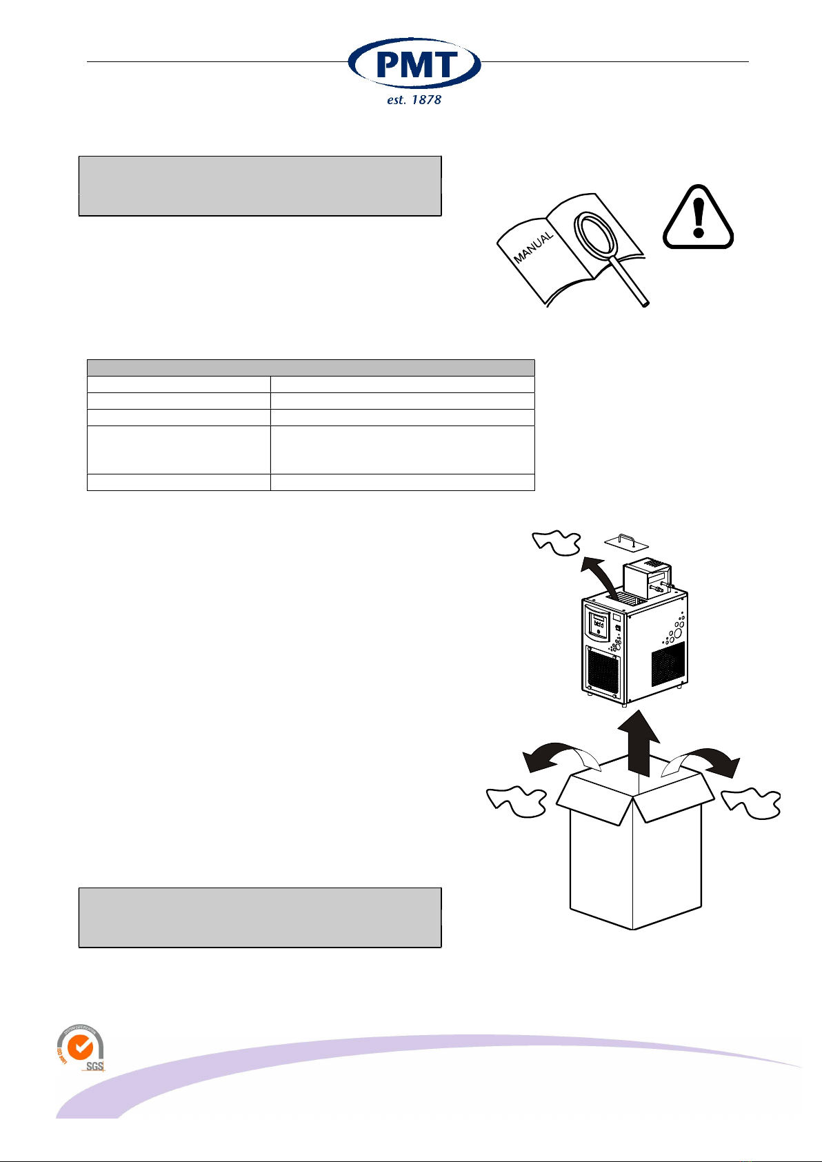
5.1 UNPACKING ..................................................................................................................................................... 8
5.2 INITIAL USE ...................................................................................................................................................... 9
5.3 PLACEMENT AND VENTILATION .................................................................................................................... 9
5.4 FILLING THE BATH ......................................................................................................................................... 10
6 CONNECTING ........................................................................................................................................ 14
7 INTRODUCTION TO THE SERIES ........................................................................................................ 15
7.1 GENERAL ........................................................................................................................................................ 15
7.2 BACKSIDE OF APPARATUS .......................................................................................................................... 16
7.3 USING THE OVERFLOW OUTLET ................................................................................................................. 17
7.4 EXTERNAL PUMP ........................................................................................................................................... 19
7.5 COOLING THE BATH (TTU - TB) .................................................................................................................... 20
8 OPERATION ........................................................................................................................................... 22
8.1 SWITCHING ON .............................................................................................................................................. 22
8.2 CAUTION WITH POWERING ON/OFF ............................................................................................................ 22
8.3 CONTROL PANEL ........................................................................................................................................... 22
8.3.1 USING OVER-TEMPERATURE PROTECTION ...................................................................................... 22
8.3.2 FRONT PANEL KEYS ............................................................................................................................. 23
8.3.3 DISPLAY READOUT ............................................................................................................................... 24
8.4 MENU ITEMS .................................................................................................................................................. 24
8.5 PID CONFIGURATION .................................................................................................................................... 27
9 QUICK START ........................................................................................................................................ 28
10 USING PID FOR STABLE TEMPERATURE CONTROL ....................................................................... 29
10.1 ADJUST SET POINT ....................................................................................................................................... 29
10.2 TUNING THE BATH ......................................................................................................................................... 29
10.3 MANUAL TUNING ........................................................................................................................................... 30
10.4 DRAINING BATH FLUID .................................................................................................................................. 31
10.5 USING THE DRAIN TAP .................................................................................................................................. 31
10.6 MAINTENANCE ............................................................................................................................................... 33
11 TROUBLE SHOOTING ........................................................................................................................... 34
11.1 GENERAL ........................................................................................................................................................ 34
12 SPECIFICATION ..................................................................................................................................... 35
12.1 TECHNICAL SPECIFICATIONS OVERVIEW .................................................................................................. 35
13 SPARE PARTS ....................................................................................................................................... 37
14 DISCLAIMER .......................................................................................................................................... 39

E-mail: in[email protected]
Website: www.tamson.com
van 't Hoffstraat 12
2665 JL Bleiswijk, THE NETHERLANDS
T. 31 (0) 10 522 43 73
ttu-tb-tlb-tlc.docx Rev. 1.04 UK 0720
Tamson Instruments B.V.
Page 3/39
VAT: NL 80 66 34 984 B01
Bank account no.:
NL28
INGB 0007 350 370
NL95 RABO
0160100046
Chamber of commerce 27 16 95 41
ISO 9001 : 2015
NL/PRO 238239125
1 SAFETY AND WARNINGS
Make sure before installing or operating the equipment to read and understand all instructions and safety
precautions listed in this manual. If there are any questions concerning the operation of the equipment or
about the information given in this manual please contact your local dealer or our sales department first.
Performance of installation, operation, or maintenance other than those described in this manual may result
in a hazardous situation and may void the manufactures warranty.
Never operate equipment that is not correctly installed. Unqualified personnel must not operate the
equipment. Avoid damage to the equipment, or its accessories, caused by incorrect operation.
Important:
- When performing service, maintenance or moving the apparatus, always disconnect the line cord of
the apparatus,
- Proper skilled and trained personnel are only allowed to operate this equipment,
- Take notice of warning labels and never remove them,
- Refer service and repairs to qualified technician,
- If a problem persists, call your supplier or Tamson Instruments B.V..
2 WARRANTY
Tamson Instruments B.V. warrants that all their manufactured equipment is free from defects in material and
workmanship, preventing the machine from normal operation. Tamson Instruments B.V. does not warranty
that the equipment is fit for any other use than stated in this manual. The manufacturer can only be held
responsible for the security, reliability and performance of the equipment, when operated in accordance with
the operating instructions, extensions, adjustments, changes and/or if repair is performed by Tamson
Instruments B.V. or authorized persons only. This warranty is limited to one year from the date of invoicing.
All equipment and materials are subject to standard production tolerances and variations.

E-mail: in[email protected]
Website: www.tamson.com
van 't Hoffstraat 12
2665 JL Bleiswijk, THE NETHERLANDS
T. 31 (0) 10 522 43 73
ttu-tb-tlb-tlc.docx Rev. 1.04 UK 0720
Tamson Instruments B.V.
Page 4/39
VAT: NL 80 66 34 984 B01
Bank account no.:
NL28
INGB 0007 350 370
NL95 RABO
0160100046
Chamber of commerce 27 16 95 41
ISO 9001 : 2015
NL/PRO 238239125
3 EC DECLARATION OF CONFORMITY
Following equipment is in complience with EMC Directive 2014/30/EU:
Product: Thermostatic bath and circulator
Model: TC6b, TC10b, TC20b, TLC10, TLC15, TLC30, TB30, TLB50
Serial code: Effective from 07Txxx
Manufacturer: Tamson Instruments bv
van 't Hoffstraat 12
2665 JL Bleiswijk
The Netherlands
The products are in conformity with the following specifications:
Item
Reference
Description
Test result
a
RoHS Directive
2011/65EU p
b EN61010-2-010 Safety requirements for electrical
equipment for measurement, control,
and laboratory use. Particular require-
ments for laboratory equipment for the
heating of material
c Machine Directive
2006/42/EC
Machinery Directive, of the European
Parliament and of the Council of 17 May
2006/42/EC 2nd Edition June 2010
p
d EN 60204 Machinery Directive and Safety
requirements
p, pi
e
EN60950
-
1
Low Voltage Directive p
f
EN61000
-
3
-
2:2014
Harmonics p
g
EN61000
-
3
-
3
Flicker p3
h
EN61000
-
4
-
2 +A1+A2
ESD p
j
EN61000
-
4
-
3 +A1+A2
Radiated immunity p (anechoic room)
k
EN61000
-
4
-
4
Electrical Fast Transients Minimum requirements pass
l
EN61000
-
4
-
5+A1
Surges Minimum requirements pass
m
EN61000
-
4
-
6+A1
Conducted immunity p
n
EN61000
-
4
-
11 +A1
Voltage dips and Voltage variations p
o
EN55016
-
2
-
1
Conducted emission p
p
EN55016
-
2
-
3
Radiated emission p (anechoic room)
q Pr EN 378 Refrigerating systems and heat pumps -
Safety and environmental requirements
r EN 13445-5 PED Inspection and Testing Maximum working pressure level
of 20 Bar is confirmed.
On each apparatus following
pressure and leak tests have
been carried out with positive
result
- Low pressure side 10 Bar
- High pressure side
25
Ba
r
p = Pass
pi = Individually tested
p3 = Pass, condition of operating during Pst measurement: Operational with heating element 1400W.
Pst and Plt are not evaluated in accordance with A.5 of Annex A of EN 61000-3-3(1995) + A1(2001).

E-mail: in[email protected]
Website: www.tamson.com
van 't Hoffstraat 12
2665 JL Bleiswijk, THE NETHERLANDS
T. 31 (0) 10 522 43 73
ttu-tb-tlb-tlc.docx Rev. 1.04 UK 0720
Tamson Instruments B.V.
Page 5/39
VAT: NL 80 66 34 984 B01
Bank account no.:
NL28
INGB 0007 350 370
NL95 RABO
0160100046
Chamber of commerce 27 16 95 41
ISO 9001 : 2015
NL/PRO 238239125
not applicable were:
Conducted discontinuous emissions (Clicks)
Radiated emission (OATS)
Magnetic field immunity
The equipment conforms with all the specifications and norms in this regard.
The equipment conforms without any further notice.
Entity responsible for marking this declaration :
Manufacturer, Tamson Instruments bv, van 't Hoffstraat 12, Bleiswijk The Netherlands,
Name : R.C. van Hall
Function : Director
Date : January, 2018
Version : 1.04

E-mail: in[email protected]
Website: www.tamson.com
van 't Hoffstraat 12
2665 JL Bleiswijk, THE NETHERLANDS
T. 31 (0) 10 522 43 73
ttu-tb-tlb-tlc.docx Rev. 1.04 UK 0720
Tamson Instruments B.V.
Page 6/39
VAT: NL 80 66 34 984 B01
Bank account no.:
NL28
INGB 0007 350 370
NL95 RABO
0160100046
Chamber of commerce 27 16 95 41
ISO 9001 : 2015
NL/PRO 238239125
Part no.
Picture
Description
TTU
-
A
(Tamson Thermostatic Unit "A")
19T3110 - 230V 50-60Hz
19T3111 - 115V 60Hz
Stirring
Pump
1.1 kW Heating
19T1010 - 230V 50-60Hz
19T1011 - 115V 60Hz
Stirring
Cooling coil
1.4 kW Heating
19T3120 - 230V 50-60Hz
19T3121 - 115V 60Hz
Stirring
Short shaft
2.8 kW Heating
19T1020 - 230V 50-60Hz
19T1021 - 115V 60Hz
Stirring
Long shaft
2.8kW Heating

E-mail: in[email protected]
Website: www.tamson.com
van 't Hoffstraat 12
2665 JL Bleiswijk, THE NETHERLANDS
T. 31 (0) 10 522 43 73
ttu-tb-tlb-tlc.docx Rev. 1.04 UK 0720
Tamson Instruments B.V.
Page 7/39
VAT: NL 80 66 34 984 B01
Bank account no.:
NL28
INGB 0007 350 370
NL95 RABO
0160100046
Chamber of commerce 27 16 95 41
ISO 9001 : 2015
NL/PRO 238239125
TB30
(Tamson Bath 30 litres)
00T0069 - 230V 50-60Hz
00T0070 - 115V 60Hz
D1838 version
00T0065 - 230V 50-60Hz
00T0066 - 115V 60Hz
TLB50
(Tamson Low temperature Bath 50 litres)
00T0072 - 230V 50Hz
00T0071 - 115V 60Hz
00T0073 - 230V 60Hz
D892 FOAM
(ASTM – D892 Foam testing bath 40 litres)
19T3122 - 230V 50Hz
19T3123 - 115V 60Hz
TLC
(Tamson Low temperature Circulator)
00T0050 - 230V 50Hz
00T0052 - 115V 60Hz
00T0051 - 230V 60Hz
Bath 3 litres
External circulation
-10 .. 60°C
-10 .. 150°C optional
00T0565 - 230V 50Hz
00T0570 - 115V 60Hz
00T0567 - 230V 60Hz
Bath 5 litres
External circulation
-15 .. 60°C
-15 .. 120°C optional
00T0555 - 230V 50Hz
00T0560 - 115V 60Hz
00T0562 - 230V 60Hz
Bath 5 litres
External circulation
-30 .. 60°C
-30 .. 120°C optional

E-mail: in[email protected]
Website: www.tamson.com
van 't Hoffstraat 12
2665 JL Bleiswijk, THE NETHERLANDS
T. 31 (0) 10 522 43 73
ttu-tb-tlb-tlc.docx Rev. 1.04 UK 0720
Tamson Instruments B.V.
Page 8/39
VAT: NL 80 66 34 984 B01
Bank account no.:
NL28
INGB 0007 350 370
NL95 RABO
0160100046
Chamber of commerce 27 16 95 41
ISO 9001 : 2015
NL/PRO 238239125
4 PRECAUTIONS AND HAZARDS
Before attempting to operate the bath read all parts of this
manual carefully to insure smooth operation and avoid
damage to the equipment or its accessories.
If a malfunction occurs, consult section "TROUBLE
SHOOTING", page 34
If a problem persists, call your supplier or Tamson
Instruments B.V. Never operate the equipment if not
correctly installed. The equipment must be operated only
by qualified personnel. Avoid damage to the equipment
or its accessories through incorrect operation.
Environment
Panel sealing Confirms EN60529: IP65
Environment Temperature 0 tot 35°C. Supply enough ventilation
Humidity 5 tot 95 %, non condensating
Atmosphere Not suited for altitudes above 2000m
or
explosive/corrosive environment
Pollution cat. 2 Conducting pollution must be prevented
5 INSTALLATION
Tamson Instruments B.V. is not responsible for any
consequential damage or harm caused by using this
bath. Repairs on the electrical system of the bath may
only be carried out by well trained and authorized
persons.
5.1 UNPACKING
To avoid damage during transport all Tamson baths are
carefully packed for shipment. Check the packaging for
external damage and make a note on the shipping
documents if any damage is found. Always retain the
cartons and packing material until the bath has been
tested and found in good condition. Transport companies
generally will not honor a claim for damages if the
respective box is not available for examination. The
shipment contains at least the bath/circulator. The
consignment may contain other parts, individually packed
in small boxes. Please see packing list for details
concerning total contents of consignment.
Before filling the bath remove any remaining packing
material from its interior. The interior of the bath can be
accessed by taking off the lid on the top of the bath.
Unpack the apparatus with care. Do not use sharp tools for
unpacking, these can damage the bath. Keep the
packaging until you’re fully assured that the apparatus is
READ
CAREFULLY

E-mail: in[email protected]
Website: www.tamson.com
van 't Hoffstraat 12
2665 JL Bleiswijk, THE NETHERLANDS
T. 31 (0) 10 522 43 73
ttu-tb-tlb-tlc.docx Rev. 1.04 UK 0720
Tamson Instruments B.V.
Page 9/39
VAT: NL 80 66 34 984 B01
Bank account no.:
NL28
INGB 0007 350 370
NL95 RABO
0160100046
Chamber of commerce 27 16 95 41
ISO 9001 : 2015
NL/PRO 238239125
functioning properly. In case of return of the apparatus, we
will only accept original packaging.
5.2 INITIAL USE
Before filling the bath make sure that the bath is clean.
Place the bath spirit level, and connect it to the mains
after the mains-switch is placed in “off” position. Use a
mains-supply with proper grounding.
Important: Never use the bath without fluid
Following applies cooling equipment (TLC and TLB):
When the apparatus has been tilted or transported,
allow the bath a few hours for stabilization.
Do not switch on power, because lubrication-oil inside the
compressor system has to run into the capillary.
It will take several hours before the oil has flown back into
the compressor unit. When the apparatus is immediately
turned on after it has been tilted,
damage may occur to the compressor unit due to
insufficient lubrication.
5.3 PLACEMENT AND VENTILATION
The bath has to be placed in a well ventilated area.
Do not place the bath in a dusty environment. Dust will
block the condenser unit inside the apparatus which will
lead to severe mechanical damage.
Air must circulate freely. Keep 10 cm of free space at both
sides and 15 to 20 cm at the rear of the bath.

E-mail: in[email protected]
Website: www.tamson.com
van 't Hoffstraat 12
2665 JL Bleiswijk, THE NETHERLANDS
T. 31 (0) 10 522 43 73
ttu-tb-tlb-tlc.docx Rev. 1.04 UK 0720
Tamson Instruments B.V.
Page 10/39
VAT: NL 80 66 34 984 B01
Bank account no.:
NL28
INGB 0007 350 370
NL95 RABO
0160100046
Chamber of commerce 27 16 95 41
ISO 9001 : 2015
NL/PRO 238239125
5.4 FILLING THE BATH
The bath-fluid level must be 10- tot 20 mm below the
edge of the top-plate.
In al cases the heating element must be kept fully
submersed during use. A low fluid level will cause
severe damage to the heating element and also may
cause fire when flamable bath fluid is used.
For working temperatures above +80°C a fluid with a high
boiling point must be used. The bath fluid also has to be
chemically stable and must have low viscosity preventing
damage to the pump. Tamson oil type 150 has these
characteristics and is recommended to use for
temperature ranges which lie between +80°C and
+150°C.
Silicon oil type 200-10 can be used for temperatures
between +20°C en 150°C. This oil also can be used at
higher temperatures but has disadvantages like shorter
lifetime due to coloring and gel-forming.
`
10
-
20 mm
Max. 60 mm

E-mail: in[email protected]
Website: www.tamson.com
van 't Hoffstraat 12
2665 JL Bleiswijk, THE NETHERLANDS
T. 31 (0) 10 522 43 73
ttu-tb-tlb-tlc.docx Rev. 1.04 UK 0720
Tamson Instruments B.V.
Page 11/39
VAT: NL 80 66 34 984 B01
Bank account no.:
NL28
INGB 0007 350 370
NL95 RABO
0160100046
Chamber of commerce 27 16 95 41
ISO 9001 : 2015
NL/PRO 238239125
It is very important to select a liquid with a viscosity of less
than 10 cSt at the operating temperature and a flash point
which is well above the operating temperature.
Do not use demineralized water. This water can lead to
corrosion of the bath and moving parts. The corrosion can
wear out the pump bearings.
Only use water as a bath fluid below 80°C/176°F.
Working for a longer period with water at temperatures
above 80°C will damage the stirrer bearings.
Flash point must be well above the operating
temperature.
When viscosity of the bath fluid is too high at room
temperature, the motor-fuse will be activated. In such a
case the bath fluid can first be heated to set point
temperature. When the bath has reached it’s set point the
motor fuse can be reset by pressing it. This way of
operating will reduce the life of the motor and is thus not
recommended.
Type Remarks Life Viscosity [cSt]
X
Temp.
Range
Package
Ordering
code
150°C 200°C 250°C 80°C 100°C
150°C
200°
C
Mineral
T150
Yellow
Mineral oil
1/2 yr X X 20 7 3 80..150°
C
20 ltrs 00T0220
Silicon
200 -10
Transparent
Dimethyl siloxane
polymer
No limit
200hrs <10hrs 4 3.5 2.5 20..150°
C
20 ltrs 08T0001
Silicon
200 -50
Transparent
Dimethyl siloxane
polymer
No limit
200hrs <10hrs 20 15 9 80..150°
C
20 ltrs 00T0226
Silicon
Silicon 210
Dark
Dimethyl poly
siloxane
No limit
<2yrs <1yr (35) 30 22 12 80..250°
C
20 ltrs 00T0231
Silicon
Silicon 550
Colorless
Polyphenyl methyl
dimethyl siloxane
No limit
<1yr <1200
hrs
(50) 20 12 5 80..250°
C
20 ltrs 00T0238
METHANOL
FLASHPOINT
MUST BE HIGHER
THAN OPERATING
TEMPERATURE

E-mail: in[email protected]
Website: www.tamson.com
van 't Hoffstraat 12
2665 JL Bleiswijk, THE NETHERLANDS
T. 31 (0) 10 522 43 73
ttu-tb-tlb-tlc.docx Rev. 1.04 UK 0720
Tamson Instruments B.V.
Page 12/39
VAT: NL 80 66 34 984 B01
Bank account no.:
NL28
INGB 0007 350 370
NL95 RABO
0160100046
Chamber of commerce 27 16 95 41
ISO 9001 : 2015
NL/PRO 238239125
Ensure a correct fluid level. The heating element must be
kept fully submersed during use.
TB30 bath
TLB50 Low temperature bath
Bath content level
must be above
the heaters!
When level is too
low, there is great
risk of fire!
Bath content level
must be above
the heaters!
When level is too
low, there is great
risk of fire!

E-mail: in[email protected]
Website: www.tamson.com
van 't Hoffstraat 12
2665 JL Bleiswijk, THE NETHERLANDS
T. 31 (0) 10 522 43 73
ttu-tb-tlb-tlc.docx Rev. 1.04 UK 0720
Tamson Instruments B.V.
Page 13/39
VAT: NL 80 66 34 984 B01
Bank account no.:
NL28
INGB 0007 350 370
NL95 RABO
0160100046
Chamber of commerce 27 16 95 41
ISO 9001 : 2015
NL/PRO 238239125
TLC10 cooling circulator
TLC15 cooling circulator
Bath content level
must be above
the heaters!
When level is too
low, there is great
risk of fire!
Bath content level
must be above
the heaters!
When level is too
low, there is great
risk of fire!

E-mail: in[email protected]
Website: www.tamson.com
van 't Hoffstraat 12
2665 JL Bleiswijk, THE NETHERLANDS
T. 31 (0) 10 522 43 73
ttu-tb-tlb-tlc.docx Rev. 1.04 UK 0720
Tamson Instruments B.V.
Page 14/39
VAT: NL 80 66 34 984 B01
Bank account no.:
NL28
INGB 0007 350 370
NL95 RABO
0160100046
Chamber of commerce 27 16 95 41
ISO 9001 : 2015
NL/PRO 238239125
6 CONNECTING
Before plugging the appartus into the mains socket, make
sure the voltage of the bath corresponds to the local
voltage and frequency.
Use a mains supply that is well earthed, clean of
interference and suitable for the acquired electrical load
of the bath.
USE PROPERLY
EARTHED MAINS
CHECK VOLTAGE
AND
FREQUENCY

E-mail: in[email protected]
Website: www.tamson.com
van 't Hoffstraat 12
2665 JL Bleiswijk, THE NETHERLANDS
T. 31 (0) 10 522 43 73
ttu-tb-tlb-tlc.docx Rev. 1.04 UK 0720
Tamson Instruments B.V.
Page 15/39
VAT: NL 80 66 34 984 B01
Bank account no.:
NL28
INGB 0007 350 370
NL95 RABO
0160100046
Chamber of commerce 27 16 95 41
ISO 9001 : 2015
NL/PRO 238239125
7 INTRODUCTION TO THE SERIES
The TAMSON baths are used for precise temperature
control. This series offers a choice in multiple bath
volumes, different cooling capacities and operating
temperature ranges.
7.1 GENERAL
The TAMSON baths are constructed throughout from
corrosion-resistant – stainless steel and brass materials.
Outher casing is zinc plated powder coated steel. The
bath is effectively insulated against heat loss by a layer
of Armaflex® rubber between the inner tank and outer
casing.
1. Control panel
2. Mains switch
3. Safety thermostat
4. Free air flow
5. External circulation
6. Pump / stirrer housing
7. Lid / Bath opening

E-mail: in[email protected]
Website: www.tamson.com
van 't Hoffstraat 12
2665 JL Bleiswijk, THE NETHERLANDS
T. 31 (0) 10 522 43 73
ttu-tb-tlb-tlc.docx Rev. 1.04 UK 0720
Tamson Instruments B.V.
Page 16/39
VAT: NL 80 66 34 984 B01
Bank account no.:
NL28
INGB 0007 350 370
NL95 RABO
0160100046
Chamber of commerce 27 16 95 41
ISO 9001 : 2015
NL/PRO 238239125
7.2 BACKSIDE OF APPARATUS
TLC15 and TLC30
1. Outlet (pressure side)
2. Inlet (return)
3. Motorfuse / motorspeed with optional pump
4. External PT100 (optional)
5. Overflow
6. Bath drain
7. Power supply
TB30
1 Cooling coil
2 Mains cord
3 Connectors (optional)
4 Overflow outlet
5 Cooling fan (optional)
6 Bath drain
The cooling fan is available on partnumbers
00T0065 and 00T0066. The fan enables stable
temperature control around a SP of 100°C
(37,8°C) without using the cooling coil. This
temerature is used especially when performing
D1838 tests. Ambient temperature has to be below
25°C to ensure stable control though. The fan
switches automatically on when a SP is selected
below 50°C.
The maximum set point temperature is limited for
partnumbers 00T0065 and 00T0066 to 80°C.
Partnumbers 00T0067, 00T0068, 00T0069 and
00T0070 offer a maximum operating temperature
but have no fan mounted. In these the built in
cooling coil can be used when working at lower
temperatures.
1
2
3
4
5
6

E-mail: in[email protected]
Website: www.tamson.com
van 't Hoffstraat 12
2665 JL Bleiswijk, THE NETHERLANDS
T. 31 (0) 10 522 43 73
ttu-tb-tlb-tlc.docx Rev. 1.04 UK 0720
Tamson Instruments B.V.
Page 17/39
VAT: NL 80 66 34 984 B01
Bank account no.:
NL28
INGB 0007 350 370
NL95 RABO
0160100046
Chamber of commerce 27 16 95 41
ISO 9001 : 2015
NL/PRO 238239125
7.3 USING THE OVERFLOW OUTLET
When the bath fluid rises, excessive fluid can leave the
bath via the overflow (5) outlet.
This can be the case when fluid retrieves from an external
load when switching off the pump. Or when (re)filling the
bath fluid.
Connect a hose onto the outlet pipe (12mm outer
diameter) and connect to a waste container.
When working at higher temperatures, the waste
container must be able to withstand these temperatures.

E-mail: in[email protected]
Website: www.tamson.com
van 't Hoffstraat 12
2665 JL Bleiswijk, THE NETHERLANDS
T. 31 (0) 10 522 43 73
ttu-tb-tlb-tlc.docx Rev. 1.04 UK 0720
Tamson Instruments B.V.
Page 18/39
VAT: NL 80 66 34 984 B01
Bank account no.:
NL28
INGB 0007 350 370
NL95 RABO
0160100046
Chamber of commerce 27 16 95 41
ISO 9001 : 2015
NL/PRO 238239125
Setup for overflow protection TB30
Setup for overflow protection TLB50
Setup for overflow protection TLC10
Connect outlet
to waste
container
Tubing and waste
container:
Chemical resistant and
withstand high
temperature

E-mail: in[email protected]
Website: www.tamson.com
van 't Hoffstraat 12
2665 JL Bleiswijk, THE NETHERLANDS
T. 31 (0) 10 522 43 73
ttu-tb-tlb-tlc.docx Rev. 1.04 UK 0720
Tamson Instruments B.V.
Page 19/39
VAT: NL 80 66 34 984 B01
Bank account no.:
NL28
INGB 0007 350 370
NL95 RABO
0160100046
Chamber of commerce 27 16 95 41
ISO 9001 : 2015
NL/PRO 238239125
7.4 EXTERNAL PUMP
To ensure uniform temperature control all models have a
built in stirring mechanism. Additional to the stirring, the
TLC and TTU (can) offer the possibilty to circulate fluid
trough an external closed system
Both stirrer and pump are protected bij a fuse. This motor
protection fuse is located on the backpanal of the motor
housing
When pumping viscous liquids the thermal fuse can be
activated. The motor fuse can be reset by pressing the
button.
The inlet and outlet of the pump are fitted with 8 mm hose
connections and 1/4” threaded fittings for metal tubing.
The outlet is closed by a small disc, stopping the
circulation action.
Before the fluid can begin circulating through external
systems this disc must be removed by unscrewing the
fitting and hose connection removing the disk.
REMOVE DISK
WHEN
CIRCULATING
PRESS
BUTTON TO
RESET MOTOR
FUSE

E-mail: in[email protected]
Website: www.tamson.com
van 't Hoffstraat 12
2665 JL Bleiswijk, THE NETHERLANDS
T. 31 (0) 10 522 43 73
ttu-tb-tlb-tlc.docx Rev. 1.04 UK 0720
Tamson Instruments B.V.
Page 20/39
VAT: NL 80 66 34 984 B01
Bank account no.:
NL28
INGB 0007 350 370
NL95 RABO
0160100046
Chamber of commerce 27 16 95 41
ISO 9001 : 2015
NL/PRO 238239125
7.5 COOLING THE BATH (TTU - TB)
When using the bath fluid around ambient temperatures
it is difficult to realise stable temperature regulation. This
is caused by the self heating of the bath due to the
insulation and friction of the pump/stirrer. This can cause
a raise of temperature in the bath up to 30 .. 40°C
depending on the environmental temperature and bath
volume.
.
Use fluid 5°C lower than the bath setpoint
temperature. When using tap water, minimise
flow for environmental reasons.
Cooling coil has 8mm outher diameter
Cooling is need for set point temperatures of
approximately 42°C and lower
The TB30 is equipped with a cooling fan,
providing lower bath temperature near ambient.
This fan switches on automatically when working
at lower bath temperatures.
External cooling on a TTU-A using
the cooling coil available on models
19T1010 and 19T1001.
External cooling:
Connect to tap
water or chiller
TB30
The TLB50 has internal
cooling
TLB50
This manual suits for next models
31
Table of contents
Other PMT Laboratory Equipment manuals
Popular Laboratory Equipment manuals by other brands

Plasmapp
Plasmapp Sterlink FPS-15s Plus user manual

EPS
EPS EL 3160-60A instruction manual

VERDER
VERDER Carbolite Gero HTCR 5/220 Installation, operation and maintenance instructions

Brooks
Brooks CoolCell SV10 Instructions for use

Sheldon
Sheldon Shel-Lab SVAC1-2 Installation and operation manual

IKA
IKA STARVISC 200-2.5 control manual