Scientific 500 R00 User manual

4-INS-500
INSTALLATION,
OPERATION AND
CARE MANUAL
Laboratory Equipment
REMEMBER TO COMPLETE THE ONLINE
WARRANTY REGISTRATION TO
RECEIVE YOUR FULL TWO YEAR WARRANTY.
MANUFACTURED
IN SOUTH AFRICA
www.scientific.co.za
All Scientific equipment comes with a standard ONE year warranty, The 1 Year
Extended Warranty is only valid for customers who have registered their warranty
online at www.scientific.co.za within the first year after making their purchase.
WARRANTY

THANK YOU FOR PURCHASING
A SCIENTIFIC PRODUCT!
REGISTER ONLINE TODAY
Register your warranty on-line at www.scientific.co.za today and learn how to get
the best out of your Scientific product.
NO WEB ACCESS?
If you do not have access to the Web, register by completing this form and Email it
to the Scientific head oce in South Africa. Email: sales@scientific.co.za
Company
Name
Surname
Telephone
Cellphone
Email Address
Country
Postal address
Scientific products purchased
Product Code (see box label)
Serial number (see back of machine)
ONLY COMPLETE IF YOU DO NOT HAVE WEB ACCESS
INTENDED USE
Agriculture
Automotive
Biochemistry
Botony
Chemistry
Cosmetics
Electronics
Food
Genetics
Industrial
Medical
Microbiology
Mining
Nuclear
Paper/Packaging
Petrochemical
Pharmaceutical Physics
Power Generation
Special Metals
Sugar
Water
Zoology
Other (Specify):
ALL SCIENTIFIC EQUIPMENT COMES WITH A TWO
YEAR WARRANTY ON COMPONENTS AND
DEFECTIVE WORKMANSHIP - Ts & Cs APPLY.
QUALITY
GUARANTEED
ALL SCIENTIFIC EQUIPMENT COMES WITH A TWO
YEAR WARRANTY ON COMPONENTS AND
DEFECTIVE WORKMANSHIP - Ts & Cs APPLY.
QUALITY
GUARANTEED
Laboratory
Equipment
www.scientific.co.za

4-INS-500 R01
INSTALLATION OPERATION AND CARE OF
LABORATORY HOTPLATES
MODELS: 500 R00/501 R00 / 502 R00
LABORATORY HOTPLATES
LIMITED WARRANTY
The manufacturer guarantees that this unit is free from defect in ma-
terials and workmanship when it leaves the factory and undertakes to
replace or repair the unit if it proves defective in normal use or during
servicing for a period of 1(one) year. The date of original installation
and is for the benet of the original purchaser only. The liability under
this warranty is limited to repairing the defective unit or any part of
the unit provided it is sent carriage paid to an authorized dealer. All
other Warranties ,expressed or implied , statutory or otherwise, in-
cluding without limitations any implied Warranty of Merchantability or
tness for purpose are excluded .The Seller shall in no event be liable
for direct,indirect or consequential damages in connection with the
products.
This unit is at all times to be used according to the instruction manual
and for its normal purpose.
This Warranty is not effective if damage occurs because of accident,
carelessness,improper installation,lack of proper set-up,supervision
when required or if the equipment is installed or operated in any
manner contrary to the installation and operating instructions. In
these cases,repairs will be made at a reasonable cost. Work per-
formed by unauthorized personnel or unauthorized service agencies
voids this Warranty.

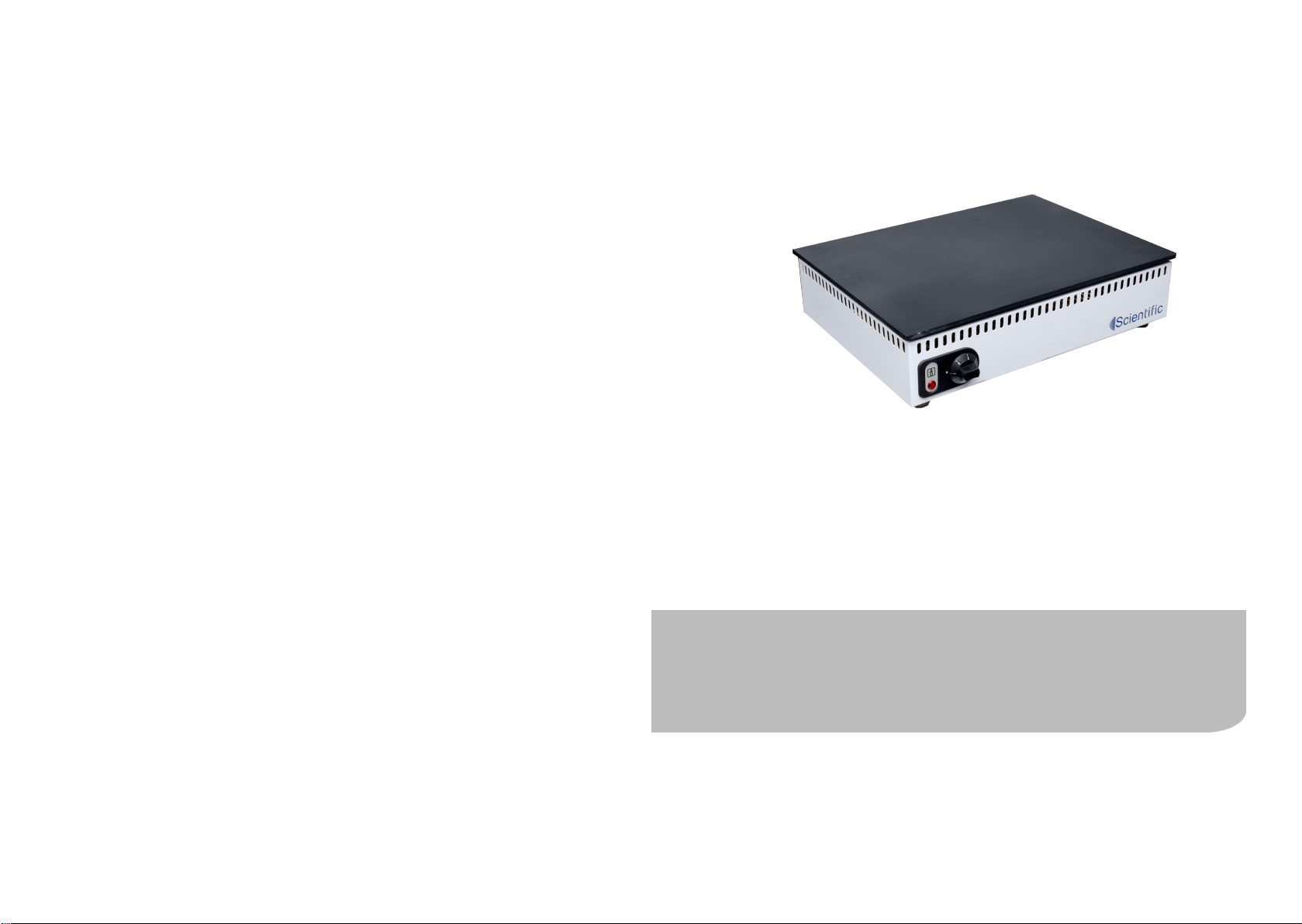
These hotplates are general purpose hotplates that are robustly con-
structed and designed for continual usage. All Models are controlled
by an energy regulator which varies the power input to the elements
enabling ner control at lower surface temperature. There is no sur-
face temperature indication.
PRODUCT DESCRIPTION
THESE INSTRUCTIONS MUST BE FOLLOWED FOR US TO
GUARANTEE OUR FULL SUPPORT OF YOUR CLAIM FOR
PROTECTING AGAINST LOSS FROM CONCEALED DAMAGE.
THE FORM FOR FILING SUCH A CLAIM WILL BE PROVIDED
BY THE CARRIER.
UNPACKING
Unpack the product and check for any damage incurred during
transit. This should be reported to the responsible carrier, railway or
postal authority, and a request for a damage report should be made.
1. Ensure that the unit is placed on a sturdy bench.
2. Install the unit away from combustible material and preferably
at least 300mm away from the wall or adjacent surfaces.
3. Check that the mains voltage complies with the rated
220-240VAC 50Hz-15 amp supply voltage and plug into power
socket.
4. To energize the heating elements turn the energy regulator
knob marked 0 to 6 to the desired setting.
5. The hotplate element will cycle on and off at the setting
selected.
6. To have the heating elements permanently energized, the knob
should be turned to position 6.
7. The hotplate top is covered with a special heat resistant
coating which may smoke initially as the unit is burned in.
This is normal.
GENERAL INSTALLATION AND OPERATION INFORMATION
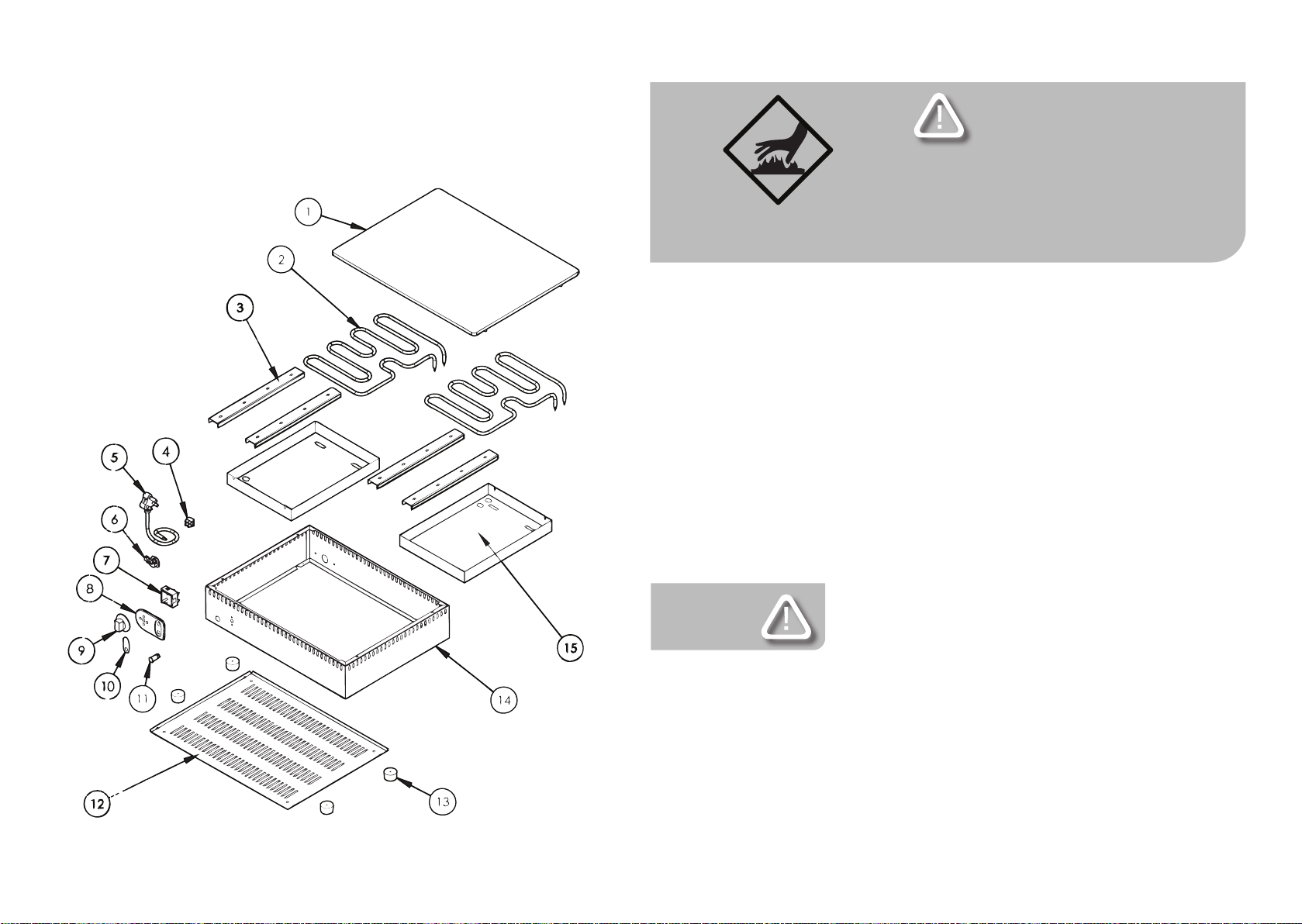
Part
No.
1 502 TOP PLATE
2 ELEMENT 1500W 230V
3 ELEMENT CLAMP
4 TERMINAL BLOCK
5 POWER CORD
6 CABLE GRIP
7 ENERGY REGULATOR
8 CONTROL PANEL
9 KNOB
10 CONTROL PANEL INSERT
11 PILOT LIGHT
12 BOTTOM COVER
13 LARGE RUBBER FOOT
14 BODY ASSEMBLY
15 ELEMENT COVER
Description
MODEL : LABORATORY HOTPLATE
MODEL CODE : 502
1 14

WARNING
Burn Hazard.
Do not touch hot,liquid or heating surfaces
while equipment is heating or operating
Hot surfaces and liquid can burn skin. Allow the hot surfaces to cool
before handling
CLEAN WITH A DAMP CLOTH AND SOAP. AVOID
THE USE OF DETERGENTS
CONTAINING ABRASIVE SUBSTANCES. DRY CARE-
FULLY AFTER CLEANING. DO NOT USE PRODUCTS
CONTAINING AGGRESSIVE CHEMICALS, ACIDS OR
PRODUCTS WITH CHLORINE.
CLEANING
• Care should be taken when operating this appliance as hot
surfaces are present which may cause burns.
• Ensure that the power supply cord does not come into contact
with hot surfaces.
• It is recommended not to leave the unit in operation
unattended.
EXPLODED DIAGRAM
LABORATORY HOT PLATES
MODELS: 502
213

SAFETY
READ ALL INSTRUCTIONS BEFORE USE. FAILURE TO
FOLLOW THESE PRECAUTIONS COULD RESULT IN INJURY TO
YOURSELF AND OTHERS
1. Use the hot plate on an individual 15A mains outlet
only. DO NOT OVERLOAD THE CIRCUIT.
2. Ensure that the equipment and the power supply cord does not
come into contact with hot surfaces.
3. This unit is only to be used by properly trained laboratory staff.
4. If the supply cord is damaged, it must be replaced with a new
cord assembly available from the suppliers agent.
5. Use only earthed outlets matching the serial plate voltage.
6. Have equipment installed by a qualied personnel in accordance
with local codes and ordinances.
7. Use equipment in a at level position.
8. Do not operate if equipment has been damaged or is malfunc-
tioning in any way.
9. These units are designed to run only on alternating current
(A.C.) DO NOT CONNECT TO DIRECT CURRENT (D.C)
WARNING
Electric Shock Hazard.
Keep water and other liquids from entering the inside
of the equipment. Liquid inside the equipment could
cause an electrical shock
Do not spray water or cleaning products. Liquid could contact the
electrical components and cause a short circuit or an electrical shock.
Do not use equipment if power cord is damaged or has been modied
Part
No.
1 ELEMENT
2 CABLE GRIP
3 TERMINAL BLOCK
4 POWER CORD
5 BODY ASSEMBLY
6 230V ENERGY REGULATOR
7 CONTROL PANEL FACIA
8 INSERT
9 RED PILOT LIGHT
10 CONTROL KNOB
11 BOTTOM COVER
12 LARGE RUBBER FOOT
13 ELEMENT COVER
14 ELEMENT CLAMP
15 TOP PLATE
Description
MODEL : LABORATORY HOTPLATE
MODEL CODE : 501
3 12

POSITIONING DIAGRAM
LABORATORY HOT PLATE
MODELS: 500/501/502
B
A
C
MODEL A B C
500 300 136 305
501 450 136 305
502 600 136 455
EXPLODED DIAGRAM
LABORATORY HOT PLATES
MODELS: 501
411

IT IS ESSENTIAL TO MAKE SURE THAT THE INCOMING
VOLTAGE IS THE SAME AS THE RATED VOLTAGE OF
THE OF THE UNIT AS FOUND ON THE SERIAL PLATE.
THE SERIAL PLATE IS LOCATED AT THE REAR OF THE
UNIT ADJACENT TO THE INCOMING CABLE ENTRY.
ELECTRICAL AND TECHNICAL INFORMATION
THE CONTROL COMPARTMENT OF THIS UNIT CON-
TAINS DANGEROUS VOLTAGES. MAINTENANCE AND
SERVICING REQUIRING THE REMOVAL OF ANY PAN-
ELS OR COVERS SHOULD BE DONE BY QUALIFIED
SERVICE PERSONNEL ONLY.
MODEL DESCRIPTION VOLTS
(V/Hz)
POWER
(WATTS)
500 HOTPLATE 300mm 230/50 1500
501 HOTPLATE 450mm 230/50 2000
502 HOTPLATE 600mm 230/50 3000
Part
No.
1 BODY ASSEMBLY
2 ELEMENT COVER
3 TERMINAL BLOCK
4 CABLE GRIP
5 POWER CORD
6 ELEMENT
7 TOP PLATE
8 ELEMENT CLAMP
9 230V ENEEGY REGULATOR
10 CONTROL PANEL FACIA
11 INSERT
12 PILOT LIGHT
13 CONTROL KNOB
14 BOTTOM COVER
15 LARGE RUBBER FOOT
Description
MODEL : LABORATORY HOTPLATE
MODEL CODE : 500
ACCESSORIES AVAILABLE
MODEL 513 -SAND BATH ATTACHMENT
MODEL DESCRIPTION ORDER CODE
500 SAND BATH ATTACHMENT 509
501 SAND BATH ATTACHMENT 510
513 SAND BATH ATTACHMENT 502
5 10

EXPLODED DIAGRAM
LABORATORY HOT PLATES
MODELS: 500
230V
L
N
E
E1
42
S2
P1
P2
S1
ER
H1
WIRING DIAGRAM
MODEL: LABORATORY HOT PLATE
MODEL CODES: 500/501
69

230V
L
N
E
E1
42
S2
P1
P2
S1
ER
H1
E2
LEGEND DESCRIPTION PART NUMBER
ER ENERGY REGULATOR 1-ER-URS0012
H1 HEAT CONTROL PILOT LIGHT 1-PL-GP
E1/E2 ELEMENT 1500W/230V 5-1500W-GRILLER
WIRING DIAGRAM
MODEL: LABORATORY HOT PLATE
MODEL CODES: 502
LEGEND DESCRIPTION PART NUMBER
ER ENERGY REGULATOR 1-ER-URS0012
H1 HEAT CONTROL PILOT LIGHT 1-PL-GP
E1/E2 ELEMENT 1500W/230V 5-2000W-M/GRILL
WIRING DIAGRAM LEGEND
MODEL: LABORATORY HOT PLATE
MODEL CODES: 501
LEGEND DESCRIPTION PART NUMBER
ER ENERGY REGULATOR 1-ER-URS0012
H1 HEAT CONTROL PILOT LIGHT 1-PL-GP
E1 ELEMENT 1500W/230V 5-1500W-500
WIRING DIAGRAM
MODEL: LABORATORY HOT PLATE
MODEL CODES: 500
7 8
This manual suits for next models
2
Table of contents
Other Scientific Laboratory Equipment manuals
Popular Laboratory Equipment manuals by other brands

DASIT GROUP
DASIT GROUP FASTER CYTOFAST ELITE Series Operating and maintenance manual

Miele professional
Miele professional A 104 operating instructions

Labconco
Labconco Protector XStream 9840400 user manual

PROEL
PROEL DIRECT100A user manual

Bio-Optica
Bio-Optica Trimming Tech 90 User and service manual

Specac
Specac GS10890 user manual