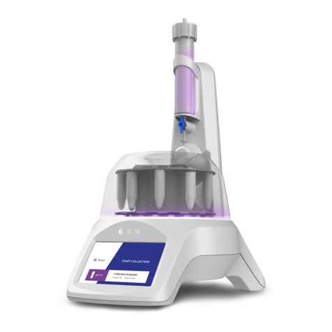
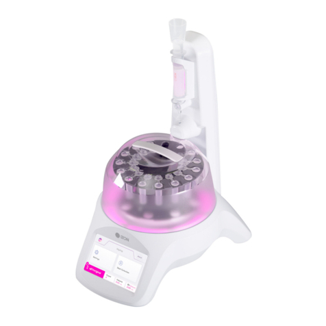
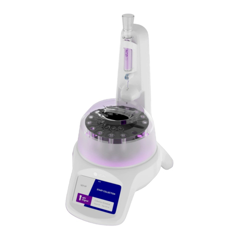
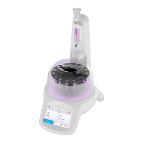
Izon EXOID User manual

www.izon.com
USER MANUAL
EXOID

Izon Science Limited provides this document to its customers with a product purchase to use in the
product operation. This document is copyright protected and any reproduction of the whole or any part
of this document is strictly prohibited, except with the written authorisation of Izon Science Limited.
The contents of this document are subject to change without notice. All technical information in this
document is for reference purposes only. System configurations and specifications in this document
supersede all previous information received by the purchaser.
Izon Science Limited makes no representations that this document is complete, accurate or error-
free and assumes no responsibility and will not be liable for any errors, omissions, damage or loss
that might result from any use of this document, even if the information in the document is followed
properly.
Izon products are designed and manufactured under a quality system certified to ISO 13485:2016.
This document is not part of any sales contract between Izon Science Limited and a purchaser.
This document shall in no way govern or modify any Terms and Conditions of Sale, which Terms and
Conditions of Sale shall govern all conflicting information between the two documents.
FCC Declaration of Conformance
This device complies with part 15 of the FCC Rules. Operation is subject to the following two conditions:
(1) This device may not cause harmful interference
(2) This device must not accept any interference received, including interference that may cause
undesired operation. Changes or modification not expressly approved by the party responsible for
compliance could void the user’s authority to operate the equipment.
Izon Science Limited Telephone: +64 3 357 4270
Addington Website: www.izon.com
Christchurch 8024
New Zealand
www.izon.com
2

TABLE OF CONTENTS
1 Definitions and Writing Conventions .......................................................................................................... 4
2 Safety and Hazards......................................................................................................................................... 6
2.1 Safe Use Requirements and Specifications ................................................................................................... 6
2.2 Hazards........................................................................................................................................................................6
2.3 Intended Use ...............................................................................................................................................................7
3 Assembly and Setup Instructions ................................................................................................................ 8
3.1 System Components ...............................................................................................................................................8
3.2 Assembling and Installing the Exoid ..................................................................................................................9
3.3 Instrument Power and General Operation ...................................................................................................... 9
3.4 General Operating Procedures............................................................................................................................9
3.5 Computer Setup...................................................................................................................................................... 10
4 Operations Instructions.................................................................................................................................12
4.1 Required Materials................................................................................................................................................. 12
4.2 Exoid Lighting........................................................................................................................................................... 13
4.3 Fluid Cell .................................................................................................................................................................... 14
4.4 Exoid Control Suite Software ............................................................................................................................. 15
5 Troubleshooting.............................................................................................................................................. 18
6 Further Support .............................................................................................................................................20
Exoid User Manual 3

DEFINITIONS AND WRITING CONVENTIONS
1 /
This symbol indicates general advice on how to improve procedures or
recommends measures to take in specific situations.
This symbol indicates where special care should be taken.
Direct Current (DC)
Voltage polarity of the jack
Make sure to follow the precautionary statements presented in this guide. Safety and other special
notifications will appear in boxes and include the symbols detailed in Table 1.
Table 1: Safety and Hazard Symbols
www.izon.com
4

Table 2: Terminology used in this manual
TERM DEFINITION
Automatic Pressure
System (APS)
A component of the Exoid which controls pressure to a limit of ±2500
Pascals (Pa).
Delta The stretcher unit consisting of a set of jaws with teeth that the
nanopore fits on to.
Exoid Control Suite (ECS) The software used to operate the Exoid.
Exoid lighting Lighting halo located around the top of the Exoid.
Izon Data Suite (IDS) The software used to process data produced by the Exoid.
Load position The stretcher unit position that enables a nanopore to be fitted onto
the teeth.
Nanopore Flexible polyurethane membrane with a nanoscale size hole in the
centre.
RMS noise Root mean square: a real-time measure of the background electrical
noise of the system.
Shielding lid Hinged cap on the top face of the Exoid which opens to reveal the fluid
cell and nanopore working area. Closing this will reduce noise from
external sources such as large machinery and fluorescent lighting.
Voltage Clamp Amplifier
(VCA)
A component of the Exoid which controls the voltage applied to the
system in order to manipulate current.
Exoid User Manual 5

2.2 Hazards
The Exoid is a laboratory product, however if any biohazardous samples are present then adhere
to current Good Laboratory Practices (cGLPs) and comply with any local guidelines specific to your
laboratory and location.
Fire or Electrical Hazard
The Exoid poses no uncommon electrical or fire hazard to operators if installed and operated properly
without physical modification and connected to a power source of correct specification.
SAFETY AND HAZARDS
2.1 Safe Use Requirements and Specifications
Make sure to adhere to the safe use requirements as specified in Table 3. If the equipment is
used in a manner not specified, protection provided by the equipment may be impaired.
Table 3: Safe use requirements and specification of the Exoid
2 /
SAFE USE REQUIREMENT SPECIFICATION
Operating Temperature Indoor Use
Ambient temperature of 5-40 ˚C is safe for the
instrument, however operation at 5-25 ˚C is
recommended.
Altitude Up to 2000 meters above sea level
Relative Humidity 20-80% relative humidity
Power Consumption 80 W
Pollution Degree Rating 2
Ingress Protection Rating IP30 / Type 1 - UL50E
Power Supply Unit
(TRH100A240-21E11 +
CCCVI)
Input AC
100-240 V
1.5 A
47-63 Hz
Output DC
24 V nom
4.17 A max current
100.08 W max power
www.izon.com
6

Chemical Hazards
The Exoid system contains no potentially hazardous chemical materials.
Mechanical Hazards
The Exoid stretcher unit contains automatically moving parts. Keep fingers and loose clothing clear
while automatic processes are in operation.
Transport
To protect the Exoid during transport or storage, decontamination procedures must first be performed.
To protect the instrument from damage, always use the packaging materials supplied when
transporting the Exoid. Use appropriate heavy lifting techniques to avoid injury. If appropriate packing
materials cannot be obtained then contact your local Izon Science office.
Disposal
The Exoid system contains electrical materials; it should be disposed of as unsorted waste and must
be collected separately, according to the European Union Directive: Waste Electrical and Electronic
Equipment. The user is fully responsible for ensuring that the obsolete Equipment and/or Consumables
are recycled or disposed of in accordance with this and/or any other relevant laws and regulations in
the countries where the instrument is being recycled or disposed of. Contact your local Izon Science
representative for more information.
2.3 Intended Use
The Exoid is used to measure size, concentration and zeta potential of nanoparticles. The instrument
is intended for use in research laboratories by professional personnel. The Exoid is not intended for
diagnostic purposes and should not be used to make treatment decisions.
For verification of the entire system, it is recommended that cGLPs are followed to ensure reliable
analyses.
Exoid User Manual 7

ASSEMBLY AND SETUP INSTRUCTIONS
3.1 System Components
The following components are provided in the box:
3 /
1Exoid Instrument 5Lower Fluid Cell
2Shielding Cap 624 V Power Supply
3Upper Fluid Cell 7Power Lead
410 MΩ Reference Cell 8USB-A to USB-C Cable
Figure 1: The Exoid and components with an Exoid.
www.izon.com
8

3.2 Assembling and Installing the Exoid
1. Unpack the Exoid and box contents.
We recommend that you save the box and packaging materials in case the instrument needs to be
returned for servicing.
If you decide to dispose of the packaging, first check that all components are present so as not to
inadvertently throw anything away.
2. Place the Exoid onto a stable and level laboratory bench.
3. Ensure that the buttons near the top of the Exoid are facing the user.
4. Connect the power lead to the 24 V power supply.
5. Ensure the Exoid is switched off, and if the power socket at the wall has a switch, ensure the switch
is turned off. Plug the power lead into a wall socket and connect the cable from the 24 V power
supply to the rear of the instrument.
6. Connect the USB cable to the instrument and the computer.
7. Turn the instrument on first using the power switch at the wall socket (if applicable) and then the
Exoid power switch.
3.3 Instrument Power and General Operation
Make sure the power supply box is positioned away from fluids.
To prevent heat buildup do not cover the power supply box.
Position the unit so it can be quickly and easily disconnected from the mains power.
Check the local supply meets the AC input requirement given in the specification.
The Exoid is to only be used with power supplies and leads provided by Izon. Failure to use the
correct power supply may result in invalid operation.
Make sure the power supply is placed away from and to the rear of the instrument to avoid coming
into contact with any spills or fluid.
Exoid User Manual 9

3.4 General Operating Procedures
For indoor use only and to be used within the rated conditions specified.
Take care not to spill fluids on electrical parts during operation.
The Exoid must be installed into Earth Grounded Protected Outlets ONLY. To minimise the influence
of external noise from the environment, position equipment away from electrical switching gear and
interfering equipment.
3.5 Computer Setup
Devices connected to the Exoid should be compliant with a relevant safety standard such as IEC
60950-1 for IT equipment or IEC 61010-1 for laboratory equipment and should provide double or
reinforced insulation from hazardous voltage sources. Always use USB cables supplied by Izon to
connect the Exoid to the computer.
Minimum Computer Specifications
For the Exoid and ECS to work effectively, the minimum PC requirements must be in place. These are as
follows:
16 GB RAM
i7 processor
256 GB SSD
Dedicated graphics processor (GPU) with at least 1 GB graphics memory
Windows 10 Pro
www.izon.com
10

Windows Home is not suitable for the installation of the ECS. Ensure that the computer is installed
with Windows Pro.
An onboard graphics card is not suitable for the operation of the Exoid. Ensure that the connected
computer has a dedicated GPU with at least 1 GB of memory and that the computer will use this
GPU while the ECS is running. Visit support.izon.com/why-does-the-ecs-lag for instructions on how
to do this.
To operate the Exoid, there are two software suites that must be installed:
Exoid Control Suite (ECS): used to control the Exoid and gather data.
Izon Data Suite (IDS): required to analyse the data collected in the ECS.
Both software packages for non 21 CFR Part 11 installations can be downloaded from:
support.izon.com/how-can-i-get-the-latest-exoid-control-suite-software-release
Exoid User Manual 11

OPERATING INSTRUCTIONS
The Exoid is a Tunable Resistive Pulse Sensing (TRPS) instrument, and requires an understanding of
the principles of TRPS to be able to effectively operate the instrument and interpret the data outputs.
Information on the principles of TRPS can be found in the Fundamentals of Tunable Resistive Pulse
Sensing Theory Manual at support.izon.com and via free online courses at academy.izon.com
4.1 Required Materials
The following materials beyond the Exoid and the control computer are required to complete a
measurement. Some of these are provided in the TRPS Training Kit that can be requested with the
instrument, as indicated by an asterisk (*).
Calibrated micropipettes: 1 µL to 1 mL
Pipette tips
Lint-free tissues for drying
Powder-free disposable gloves
Nanopore*
15 mL tubes*
1.5 mL tubes*
10 mL luer lock syringes*
Freshly prepared reagents
Diluted calibration particles
Processed and diluted sample
4 /
www.izon.com
12

4.2 Exoid Lighting
The ring of LED lights located below the buttons provides visual indications on the state of the Exoid, as
described in Table 4.
Table 4: Description of Exoid state as indicated by the halo lighting
HALO COLOUR EXOID STATE
White Connected, idle.
Red Disconnected, see Section 5.
Blue System requires user input.
Purple System performing an operation.
Exoid User Manual 13

Figure 3: The upper fluid cell has four dots (left) used to lock the cell in position. When the cell is locked in place only
one dot on each side will be visible (right).
4.3 Fluid Cell
The fluid cell is comprised of an upper and lower component (upper fluid cell and lower fluid cell) that
are positioned above and below the nanopore respectively, as well as a shielding cap that reduces
external noise which may interfere with measurements. The upper and lower fluid cells each contain
an electrode, and provide a containment for the electrolyte solution required to measure your sample.
Figure 2 provides a visual guide for normal operation of the system.
Figure 2: A cross section of the Exoid fluid cell, showing the upper and lower fluid cells, the nanopore, the lower
electrode paste, and the electrolyte holding areas for normal operation. The pressure application device (PAD) is
used to tap or plunge when stabilising the system; it is shown in (1) with the plunging side in use.
There are two pogo pins positioned on the lower fluid cell which fit into sockets on the underside of the
upper fluid cell when twisted into place correctly. To assist with this, the upper fluid cell has two position
indicators on each side which, when installed correctly, will be partially obscured by the lower fluid cell
so that only one indicator on each side is visible (Figure 3).
1. PAD is used to apply
pressure here.
2. Upper fluid cell, insert
liquid here.
3. Nanopore.
4. Lower fluid cell channel,
insert liquid here.
5. Lower fluid cell paste.
2
3
4
5
1
www.izon.com
14

4.4 Exoid Control Suite Software
If using a laptop to operate the Exoid, ensure that the laptop charging cable is plugged in and providing
power at all times during operation of the instrument.
Once the instrument is connected to the computer and switched on, open the Exoid Control Suite
(ECS). A welcome splash screen followed by the home screen will be displayed, showing a render of the
instrument with the word “CONNECTED” beneath it. There are several internal mechanics of the Exoid
which need to have completed their start-up process before this will occur. A successful connection
of all components will also be indicated by activation of the Exoid lighting. If either the lights are red
or “DISCONNECTED” is displayed, please refer to the troubleshooting guide in Section 5. Notifications
about system updates appear on the bell icon.
Figure 4: The Exoid Control Suite (ECS) home screen display when an instrument has been successfully connected.
Nanopore Loading
A correctly loaded nanopore has all four arms fitted securely onto the “teeth” of the stretcher unit at
the load position, with its serial number facing upwards.
Exoid User Manual 15

Investigation Details
This must be selected and populated for the other two options to become available.
Nanopore Setup
This section guides the user through all the appropriate procedures required to prepare the nanopore
for sample analysis.
Start Analysis
This section guides the user through all the appropriate procedures required for sample analysis.
Within this section the user has the option to select if they wish to measure size and concentration or
size and zeta potential. To enter this section, nanopore setup is recommended but it is not required.
Controlling the Exoid
The Exoid has three components that require interaction to achieve a successful sample measurement;
the APS which controls pressure, the VCA which controls voltage, and the Delta which controls stretch.
All three of these components can be controlled from within the ECS by clicking on the displayed
parameter in the device summary panel, entering the desired value and selecting the check-mark or
pressing Enter.
Figure 5: The device summary panel displaying current system parameters.
Figure 6: The stretch control buttons near the top of the Exoid.
Decrease Stretch No Function Increase Stretch
www.izon.com
16

Additionally, the Delta can be controlled via the stretch control buttons near the top of the Exoid above
the halo. The Exoid has built-in limit switches to prevent the stretcher being moved to a position that
will damage the winding mechanism, these are located at ~41 and ~51 mm. The user will not be able to
stretch beyond these values.
Guide to Real-Time Data
When using the ECS to operate the instrument, the signal trace, particle size plot and the particle size
distribution histogram provide a real-time visualisation of particles being measured by the system.
Signal trace plot: displays the baseline current as well as individual blockades when a particle
transverses the nanopore.
Particle size plot: displays each significant blockade as a dot, plotted on a relative particle size scale
in nanoamperes (nA). Also visualised on the particle size plot is the particle rate, displayed as a line.
These plots can be enlarged by selecting Full Size in the top right of the signal trace plot, similarly this
can be reversed by selecting Reduced Size. Enlarging the plot will cause the particle size distribution
histogram to be visible, which displays a live population histogram of all the blockades detected during
a particular phase.
Signal trace plot
Particle rate
(line) and particle
size plot
Figure 7: The ECS signal trace plot in a “Full Size” state with the particle size distribution histogram visible.
Exoid User Manual 17

TROUBLESHOOTING5 /
Short circuits
Electrolyte can infiltrate metal connection points inside or around the fluid cell, causing significant
noise fluctuations. Troubleshoot this by pipetting out the liquid in the upper fluid cell and observing the
current. If the current does not change from pre-liquid removal or it is a non-zero (± 3 nA) value then
there is liquid somewhere causing a short circuit. Remove the upper fluid cell, then wash and dry it,
making sure all the metal parts of the fluid cell are dry. Remove any residual liquid from the lower fluid
cell area and re-setup the nanopore.
Always ensure that you do not pipette more than 35 µL into the upper fluid cell, or more than 75 µL into
the lower fluid cell, or the fluid may leak between connection points and cause the noise to gradually
increase.
Instrument Connection
If some time has passed and instrument connection is still not complete, proceed to support.izon.com/
why-are-none-of-the-exoid-modules-connected to resolve the issue.
APS Leaking
If the APS is frequently leaking, or struggling to hold pressure, check the o-ring for damage and replace
(3 mm x 1 mm, silicone) if any damage is observed. If there is still a leak check the connector tubing for
damage or loosening, also check the bottom of the upper fluid cell for damage to the seal.
External/Environmental Noise
50/60 kHz noise from nearby laboratory equipment and ungrounded power supplies can interfere
with the instrument signal. To reduce influence from external noise, do not operate in close proximity to
large appliances with high power draw, and ensure the fluid cell cap and shielding lid are used.
Using the Reference Cell
If the user suspects there is an issue with their fluid cell that is not nanopore related, i.e. non-zero
current with 0 mV applied, non-zero current with voltage applied but no electrolyte in the system,
then the 10 MΩ reference cell can be used to diagnose this. It should be noted that it is often difficult
to diagnose the difference between a nanopore issue, a setup issue, or a fluid cell issue. Contact Izon
support for advice if unsure.
Remove the fluid cell from the Exoid and replace the lower fluid cell with the reference cell. At 0 mV the
current should be 0 ± 3 nA, at 1000 mV the current should be 100 ± 3 nA, and at -1000 mV the current
should be -100 ± 3 nA. Contact Izon support if this is not the case.
www.izon.com
18

Power Cycling
Follow these instructions carefully when the need to power cycle the instrument arises.
1. Turn off the switch on the Exoid. The off position is where the full ”O” symbol is pressed down as
indicated in Figure 8.
2. Unplug the USB and power cables from the Exoid.
3. Wait 5 full seconds.
4. Plug the USB and power cables back in to the appropriate sockets.
5. Turn on the Exoid’s power switch.
Figure 8: Switches and sockets on the Exoid.
Power Socket Power Switch USB Socket
Exoid User Manual 19

FURTHER SUPPORT6 /
Device Cleaning
When cleaning the exterior of the instrument do not use solvent-based cleaners or UV light as this
can affect the integrity of the powder coating; instead use warm soapy water. The fluid cell must
be removed before cleaning can take place. First remove the fluid cell cap and upper fluid cell. Then
remove the lower fluid cell by pulling directly up on the “arms” firmly until it releases from the fluid cell
mount.
DO NOT GET ANY SUBSTANCE INSIDE THE PIN HOLES IN THE FLUID CELL MOUNT. This will cause
major functional issues and should be remedied immediately by blow drying extremely well with
compressed air.
The components of the fluid cell which have now been removed (the fluid cell cap, the upper fluid cell,
and the lower fluid cell) can be cleaned carefully with 70% Ethanol. DO NOT use isopropyl alcohol
on any part of the fluid cell as this will cause damage. Make sure to dry everything thoroughly, with
compressed air if available, before re-assembling the fluid cell. Any liquid that remains on the pins
underneath the lower fluid cells will cause major issues when the pins are pushed back into the lower
fitting. DO NOT soak any part of the fluid cell.
Repair and Servicing
There are no user-serviceable parts. Return equipment to Izon for service.
Figure 9: Compliance label attached to the Exoid with CE and UKCA marking.
www.izon.com
20
Other manuals for EXOID
2
Table of contents
Other Izon Laboratory Equipment manuals
Popular Laboratory Equipment manuals by other brands

Dynamica
Dynamica VELOCITY15R Pro instruction manual

Getinge
Getinge 88-SERIES Technical manual

Agilent Technologies
Agilent Technologies 11970 Series user guide

Molecular Devices
Molecular Devices SpectraMax M3 user guide

ORiNG
ORiNG INJ-101GT++ Series Quick installation guide

Attonics Systems
Attonics Systems ATTO3 manual