Pneumax CAFS DS Series User manual

CAFS "DS" Series Installation Guide
Applies to Pneumax Model
120-60-DS (Deutz engine)
250-120-DS
FOR INSTALLATION CENTER USAGE ONLY
Pneumax, Inc.
8557 North 78th Ave.
Peoria, Arizona 85345
623-979-3398
Fax: 623-979-6949
www.pneumaxcafs.com

Pneumax CAFS "DS" Series Installation Guide
Page 2 of 40
Warnings, Cautions, and Notes
Warning A warning alerts you to a procedure, practice or condition that may result in death or
long-term injury to personnel or destruction of equipment.
Caution A caution alerts you to a procedure or condition that may result in serious damage to
equipment or its failure to operate as expected.
Note: A note points out important information. Failure to read the note will not result in
physical harm to personnel or equipment. It may waste time and money.
Disclaimer: These instructions are guidelines only and in no way meant to be definitive. During
installation, standard safety precautions and equipment should be used where
appropriate. Because the tools used and the skill/experience of the installer can vary
widely, it is impossible to anticipate all conditions under which this installation is
made, or to provide cautions for all possible hazards. Proper installation is the
responsibility of the purchaser. All bolts, set-screws, and belts must be checked prior
to start-up AND after the initial operation. Damages due to poor installation are the
responsibility of the installer.

Pneumax CAFS "DS" Series Installation Guide
Page 3 of 40
Table of Contents
Warnings, Cautions, and Notes .............................................................................................. 2
PNEUMAX DS Series Overview ............................................................................................. 5
Installation Overview ..................................................................................................................6
Installing the Pneumax DS CAFS ........................................................................................... 7
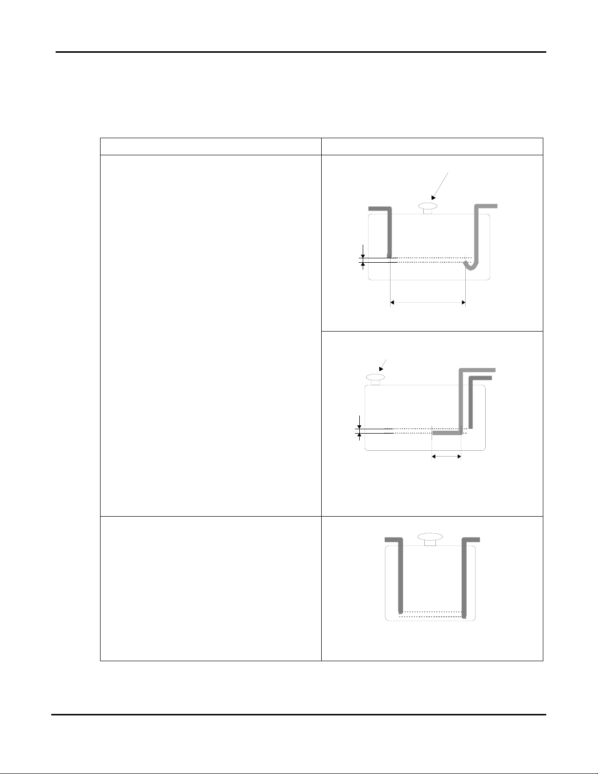
Fuel Supply ................................................................................................................................8
Water, Battery, and Oil Drain Connections ..............................................................................12
Installing the FoamPro Pump...................................................................................................14
Initial Power up ..................................................................................................................... 15
Verifying the Auto Sync Air Balancing System ..................................................................... 16
1. UNLOAD mode verification..................................................................................................16
2. FIXED mode verification ......................................................................................................16
3. AUTO mode verification.......................................................................................................16
Suggested Third-party Components ..................................................................................... 17
Suggested components for CAFS discharges:........................................................................17
Troubleshooting .................................................................................................................... 19
Diesel Motor .............................................................................................................................19
Water Pump .............................................................................................................................19
Compressor System.................................................................................................................19
Auto Sync System....................................................................................................................23
Component Identification ...................................................................................................... 26
Air Pressure and Auto Sync Components ...............................................................................26
Oil Cooler and Filters ...............................................................................................................27
Sumps ......................................................................................................................................28
Schematics and Dimensional Drawings................................................................................ 29
Modules....................................................................................................................................30
Schematics...............................................................................................................................34

Pneumax CAFS "DS" Series Installation Guide
Page 4 of 40
Revision History
Revision Date Issued Comments
1.0 Dec 2, 2005 Original Release

Pneumax CAFS "DS" Series Installation Guide
Page 5 of 40
PNEUMAX DS Series Overview
The Pneumax DS series CAF systems consist of an engine, compressor, fire pump mounted
as a modular unit on a frame with a control panel. A foam proportioner is also provided.
Pneumax Model Pump Type Engine Type
120-60-DS* Waterous CPK-1 Deutz 1011F
250-120-DS Waterous CPK-2 Volkswagen 1.9L Turbodiesel
*This version has been superceded, and is included for historical purposes only.
Connection Points:
The systems vary because of customer
requests, but the connection points
occupy the locations shown here.
The standard model has two discharges,
plumbed to the control panel. Other
discharges may be present, such as
discharges for a hose reel or deck gun.
12VDC
Connect
Terminals
Water Tank
Connections
Manifold
Controls
Motor, Pump,
and Compressor
System
Discharge
Valves and
Plumbing
X
X
X
X
Overboard
Suction
Usual Connection Point Locations
Hydraulic and Auto Sync Systems:
The position of the components of the hydraulic and Auto Sync systems varies from model
to model and may vary within units of the same model. See the component identification
photos in the rear of the manual.
Dimensions:
See the dimensional drawings in the rear of the manual for the critical measurements of the
module you are installing.

Pneumax CAFS "DS" Series Installation Guide
Page 6 of 40
Installation Overview
Warning: Do not start the engine unless the system is connected to a source of water.
The pump and compressor are in service whenever the engine is running.
Running without water will seriously damage the pump. It will also damage
the compressor.
Notes: The instructions are for a typical system. A custom order system will have a
similar installation procedure. The illustrations shown in this manual may differ
slightly from the parts that were shipped.
Pneumax systems do not include:
•Fuel pump and fuel lines
•Battery and cables
•Fittings and pipe for plumbing
Installation tasks include:
•Installing the module into the vehicle
•Installing the Foam-Pro proportioner pump (120-60-DS and 250-120-DS) and
connecting it to the controls and the foam solution distribution lines.
•Plumbing the tank fill and tank-to-pump lines to the onboard tank
•Plumbing any discharges that are not plumbed through the control panel (if any)
•Connecting the fuel system
•Connecting the battery/12VDC power supply
•Filling all system fluids
•Final testing of system

Pneumax CAFS "DS" Series Installation Guide
Page 7 of 40
Installing the Pneumax DS CAFS
Refer to the Basic CAFS schematic in this manual to see how the components connect to
the vehicle's foam and water distribution systems. Within the guidelines given here,
components can be installed wherever there is room for them to be securely mounted. See
the dimensional drawings in the rear.
Warning: Do not damage the vehicle chassis (also called frame or undercarriage) during
installation. Check with the vehicle manufacturer to make sure the planned
welds and bolts are in acceptable areas.
•The module must be bolted to brackets welded to the pump compartment frame, or
bolted directly to the pump compartment frame.
•The module must have the specified unobstructed clearances for cooling.
•The fuel tank must be installed with no more than the specified height differentials
between tank and fuel inlet. If this height differential must be exceeded, a fuel pump
capable of providing adequate fuel flow must be installed.
•Allow enough clearance at the sides of the module for routine maintenance. Most
maintenance can be performed through the top access doors, but service hatches at
the sides can make maintenance easier.
Lifting instructions
Warning: Make sure the lift and chains are rated to lift the weight of the CAFS system.
Using a Forklift
The system's drains are mounted on an
apron at the bottom of the unit. This
covers the frame.
Remove the apron at the bottom of
the system before fork-lifting.
Leave clearance between the CAFS
system and the front of the forklift to
avoid damage to the controls on the
front of the system.
Apron with drains

Pneumax CAFS "DS" Series Installation Guide
Page 8 of 40
Using an Overhead Lift or Engine Lift
Each corner of the frame has a UNC ½-
13 threaded insert for an eye bolt to use
in lifting.
Use spreader bars on the chains so that
the lifting stress on the eye bolts is
vertical.
Lifting point (1 of 4)
Engine Air Supply for Combustion and Cooling
•Only fresh air is suitable for combustion and cooling. The vehicle design must
prevent exhaust or hot air from returning to the engine intake area.
•Restrictions in the air intake and discharge must be avoided as far as possible.
•The clearance area at the rear must not be obstructed by other equipment.
•The vented access covers on top must not be obstructed by other equipment.
Required Engine Clearances
Model Clearance for Air Intake
120-60-DS 6 inches minimum between module and tank
250-120-DS 11 inches minimum between module and tank
Fuel Supply
The engines are fuel-injected diesel.
Pneumax CAFS Unit Fuel Consumption
Fuel Consumption (max)
Model Engine BHP @RPM Fuel Type (lbs/bhp-hr) gal/hr
120-60-DS Deutz F3L1011 44.9 3000 Diesel 0.399 2.52
250-120-DS VW 1.9L Turbo 75 4000 Diesel 0.500 5.28
Tank Placement
If the fuel tank is below the engine, the difference in height between the inlet tip of the fuel
supply line and the fuel inlet on the engine must not be greater than the distance given here.
If the difference is greater, a fuel-line mounted lift pump is required. The pump capacity
required will depend on the tank position and other vehicle design factors. Consult with the
fuel pump manufacturer to select a suitable pump.
If the fuel tank is above the engine, an in-line pressure regulator may be needed. Consult
with the engine manufacturer to select a suitable regulator.

Pneumax CAFS "DS" Series Installation Guide
Page 9 of 40
Maximum Vertical Fuel Lift
Model Engine Maximum vertical lift
120-60-DS Deutz F3L1011 3m (118 inches)
250-120-DS VW 1.9L Turbo 1.2m (48 inches)
Fuel Filtering
Refer to the engine user and service manual for the type of filtering provided with the
engine. Depending on the operating environment, additional filtration may be required.
If the fuel has a high water content, or if temperature fluctuations produce water
condensation in the tank, a water separator is required in the fuel supply line.
If the vehicle will be operated under extreme conditions (poor fuel quality, dirt contamination
of fuel likely, high water content, poor access to spare filters) it is strongly recommended
that a combination of strainers and filters be used in the supply line.
Fuel Tanks
The basic requirements for tanks are:
•Tanks must be ventilated adequately at any angle the engine may operate in.
•Tanks must not be galvanized with zinc or made of any metal high in zinc because
some fuels will react with the tank and build up a soapy zinc compound that clogs the
fuel injectors.
•Tanks must be constructed to have a large surface area at any fuel level to facilitate
outgassing.
•Tanks must have a sludge drain valve at the bottom.
Supply and Return Fuel Lines for Fuel Injection
•Metal lines must be non-scaling.
•If the lines are not metal, the material must be heat-resistant (to 100°C).
•Line runs must be as straight and short as possible between tank and inlets or
outlets.
•The return line must not be connected to the supply line. It must return fuel to the
tank.

Pneumax CAFS "DS" Series Installation Guide
Page 10 of 40
Fuel injection motors require a closed loop full of fuel (in lines and tank) from the tank to the
injector and back. The motor is provided with an excess of fuel, and the unused fuel flows
back to the tank. This ensures a continual supply of fuel at the injector. The return line
must end 1/2 inch below the supply line to prevent air entering the fuel loop between the
tank and auxiliary engine.
Comments Installation technique
ReturnSupply
Filler neck with tank
ventilation
12 inch minimum
recommended
½ inch
Recommended for shared tank
If the auxiliary motor will draw fuel from the
tank used by the motor that moves the truck
(the chassis tank), NFPA standards specify
that the auxiliary motor must not be able to
draw more than 75% of the fuel from the
tank.
This minimizes the chances of running out
of fuel and being unable to move the vehicle
out of a dangerous situation.
Return
Supply
Filler neck with tank
ventilation
6 inch minimum
recommended
½ inch
Alternate
Fuel Line
Alternate fuel supply and return line
layout for shared tank
If the fuel pickup for the auxiliary engine
goes to the bottom of the tank, as shown
here, the auxiliary engine can use almost all
of the fuel from the tank.
The best practice is for the supply line
opening to be 1.5 inches above the bottom
of the tank, to avoid drawing sludge or water
into the line, with the return line ending 0.5
inch below the supply line opening.
A2
ReturnSupply
Recommended for separate auxiliary tank.
NOT Recommended for shared tanks.

Pneumax CAFS "DS" Series Installation Guide
Page 11 of 40
Comments Installation technique
Ending the return line at the top of the
tank is not recommended for shared or
auxiliary tanks. The fuel will drain back
into the tank whenever the motor is shut off.
The motor will be slow to start, if it starts at
all.
This return line style also increases any
tendency of the fuel to foam.
C
ReturnSupply
Not recommended for any tank

Pneumax CAFS "DS" Series Installation Guide
Page 12 of 40
Water, Battery, and Oil Drain Connections
Water Tank:
The tank connection is at the rear of the
system, usually at the lower right corner (as
seen from the front of the module).
Rear of 250-120-DSC, with tank fitting
at lower corner.
Battery:
Connect the battery to the terminals. The
positive terminal is mounted on an insulated
block, as shown. The negative terminal is
welded directly to the system frame.
•Both positive and negative cables must
be adequately sized to supply power to
the system.
•The negative terminal must be
connected to the truck chassis.
•The chassis must be properly grounded.
12VDC Terminals
Positive (top) and Negative (bottom)
Cooler to Tank Return:
From the unused fitting on the cooler, run a
water line to a fitting on the top of the tank,
near the water input port. The fitting should
have a check valve to prevent backflow.
Diagnostic: To verify that water is flowing
through the cooler, reach into the tank and
feel for return flow.
Tank return (lower fitting)

Pneumax CAFS "DS" Series Installation Guide
Page 13 of 40
Oil drains:
Hydraulic tubing is attached to the sump and
engine oil drain fittings. The tubing is
capped, and secured for shipment. Run the
drain lines to a convenient service location.
Typical oil drain, as shipped
Water Level Indicator:
Install the water level sensor in the vehicle's
tank, following the directions included with
the sensor.
Connect the sensor to the indicator on the
front control panel.

Pneumax CAFS "DS" Series Installation Guide
Page 14 of 40
Installing the FoamPro Pump
120-60-DS and 250-120-DS
Because of limited space in the CAFS
system frame, these models require that the
FoamPro pump be installed in one of the
vehicle's compartments.
The flow meter and the foam injection fitting
are installed in the discharge line of the fire
pump. The flow meter and its tee are next to
the foam manifold. The injection fitting, or a
capped port for the fitting, will be about a foot
away from it, between the tee and the fire
pump.
Follow the instructions in the FoamPro
manual to install the proportioner pump and
control module in a convenient, protected
location. Connect the flow meter to the
control module.
Connect the output of the FoamPro pump to
the foam injection fitting.
FoamPro Flowmeter and Tee
Foam Injection Fitting

Pneumax CAFS "DS" Series Installation Guide
Page 15 of 40
Initial Power up
Post-Installation, Pre-Power up Safety Check
Before you power-up the Pneumax system:
1. Remove all tools, shop towels, hose trimmings and other debris from the compartments.
2. Check all of the unused inlets: plastic shipping caps must be removed and replaced with
the appropriate plug or cap.
3. Check all connections to tanks and discharges.
4. Check all compressor and engine fluids.
Oil used in the hydraulic system is ISO 68wt hydraulic oil. It must be "Low-
foaming" or "Anti-foam".
5. Remove the air filter plumbing and pour 8 to 16 ounces of hydraulic oil into the air inlet of
the compressor to pre-oil it.
6. Replace the air filter plumbing.
7. Fill the sump with ISO 68wt anti-foam hydraulic oil until the oil level is 1/2 way up the
sight glass. You will need to add more later, to compensate for oil that remains in the
hydraulic lines and the compressor.
Initial Power up
Warning: Do not start the engine unless the system is connected to a source of water.
The pump and compressor are operating whenever the engine is running.
Running without water will seriously damage the pump. It will also damage
the compressor.
1. Close all discharges.
2. Place the Auto Sync system in UNLOAD and AUTO (UNLOAD for electric Auto Sync)
3. Start the engine.
4. Open the tank recirculation loop (Tank Fill).
5. Turn the Auto Sync to the RUN/FIXED positions (FIXED for electric Auto Sync).
6. Verify that the oil cooler system is flowing water back to the tank.
7. Shut the engine off.
8. Allow the air pressure to bleed off, then add enough oil to the sump to bring the oil level
1/2 way up the sight glass.
DO NOT overfill. Oil used in the hydraulic system is ISO 68wt hydraulic oil. It
must be "Low-foaming" or "Anti-foam".
9. Proceed to "Verifying the Auto Sync Air Balancing System".

Pneumax CAFS "DS" Series Installation Guide
Page 16 of 40
Verifying the Auto Sync Air Balancing System
This system seldom needs adjusting. For CAFS pre-built systems, the Auto Sync system is
adjusted at the factory before shipment. The FIXED mode is factory set for 145-150 PSI. In
most cases the factory settings will be satisfactory for typical CAFS and auxiliary air
applications.
If the system fails any verification step, go to Adjusting the Auto Sync Air Balancing System
and follow the steps in the order given.
1. UNLOAD mode verification
1. Set the controls on the Auto Sync control panel to FIXED and UNLOAD (UNLOAD for
electric controls).
Manual Valve Control Electric Valve Control
2. Close all air discharges.
3. Start the engine.
4. With the engine at idle, begin water flow through a discharge or tank recirculation.
5. The main air pressure gauge will read 40-50 PSI for the 250-120-DS model. It will be
lower for the 120-60-DSC, and in some systems the gauge needle may barely move. In
UNLOAD mode, this pressure is sufficient to maintain oil circulation.
2. FIXED mode verification
1. Raise engine RPM to avoid killing the engine
2. Place the controls on the Auto Sync control panel to FIXED and RUN (FIXED for electric
controls). Wait until the compressor pressure stabilizes.
3. The air pressure should be between 145-150 PSI, and stable.
3. AUTO mode verification
1. Open the throttle until the water pressure is at 100 PSI.
2. Place the controls to AUTO and RUN (AUTO for electric systems).
3. Read the main air pressure and water discharge pressure gauges.
4. The pressure readings should be the same (air may be up to 5% higher than water).
5. Vary the fire pump discharge pressure and monitor the water and air pressure gauges.
Air pressure should rise and fall with the water pressure, matching it or up to 5% higher.

Pneumax CAFS "DS" Series Installation Guide
Page 17 of 40
Suggested Third-party Components
Note: These are guidelines useful for many installations, but selection of
third-party components is at the discretion of the system installer
or vehicle manufacturer.
Suggested components for CAFS discharges:
The installer must provide fittings and tubing to connect the CAFS components to the
vehicle's discharge outlets. These are suggested parts for the common discharge sizes. If
the planned discharge system is not covered in this guideline, please contact Pneumax.
Note: Pneumax strongly suggests that every CAFS discharge have an air check valve and
a water check valve, as shown below.
The air check valve prevents foam solution from backflowing into the compressor
and contaminating the oil. The water check valve isolates the discharge, preventing
CAF from backflowing into the foam solution manifold and exiting through another
discharge.
Compressed
Air Line
Injection
Point
Check
Valves
Foam
Solution
Valve Body Discharge
Typical CAFS Discharge
Suggested air hose
The interior diameter (I.D.) of the hose is the most important factor, and any hose with the
correct I.D. and rated to withstand the expected air system pressures (500 PSIG burst
pressure) may be used.
We have found the most cost-effective hose is the push-on type hose. H101 or H201
general-purpose hose has an acceptable working pressure. Gates, Dayco, Parker,
Weatherhead and Aeroquip brands will suffice. All of these hoses come in a variety of
colors for color-coding the lines by purpose.

Pneumax CAFS "DS" Series Installation Guide
Page 18 of 40
The other type of hose that is commonly used for air discharges is hydraulic hose. Usually
this is an SAE 100R1 type. Typically, hydraulic hose is not necessary on the air discharge
circuit, because the system air pressure will not exceed 150 psi. Also, the hose and fittings
for hydraulic hose are bulky and expensive.
Air brake hose may also be used, provided the inside diameters are correct:
.375” OD is .250” ID
.500” OD is .375” ID
.625” OD is .500” ID
.750” OD is .625” ID
Air distribution manifold:
We suggest NPT fittings with the appropriate number and size ports. However, the manifold
can be built with air brake tubing if strict attention is paid to the inside diameters:
.375” OD is .250” ID
.500” OD is .375” ID
.625” OD is .500” ID
.750” OD is .625” ID

Pneumax CAFS "DS" Series Installation Guide
Page 19 of 40
Troubleshooting
Diesel Motor
Make sure that all required maintenance has been performed, that all required fluids are at
the correct level, and that the batteries are charged and connected. If the problem persists,
see the user manual's troubleshooting section.
Water Pump
See the Waterous manual.
Compressor System
Observed Symptom Probable cause Suggested fix
Lack of air pressure from
compressor
Compressor not engaging Drive belt loose or broken Adjust tension or replace belt
Confirm 40 PSI in UNLOAD position
(200 CFM systems) and 50+ in run
position. Smaller compressors have
lower UNLOAD pressures.
Auto Sync switches not in
correct position.
Verify when in FIXED/RUN that the
pressure reflects 145-150 PSI
Air discharge solenoid not working
Repair/replace solenoid
(electric valves) Verify there
is power to the air solenoid
and check operation of
solenoid. Air solenoid working - leak between
solenoid and discharge. Repair leak.
Air check valve defective Replace or correct installation.
Trim valve out of adjustment Refer to trim valve instructions
Restricted minimum pressure
valve
Clean rust or debris from valve
Air plumbed before discharge
valve seal
Relocate to discharge side of
discharge valve
Compressor running.
No air supply to
discharges, or insufficient
air supply.
Incorrect air line size Size according to discharge and
replace line with correct size.
System functioning correctly,
pressure gauge reading
obviously incorrect.
Gauge malfunction, air line
detached
Check for air leaks, replace gauge

Pneumax CAFS "DS" Series Installation Guide
Page 20 of 40
Observed Symptom Probable cause Suggested fix
FIXED has pressure but
AUTO has no pressure
No water supply to balance
valve.
Check line for proper installation, with
no kinks or obstructions.
Refer to trim valve instructions.
Red hose circuit
(compressed air control) has
leak or is disconnected.
Repair leak or attach hose.
Air discharge pressure too
high
AITV has been opened. Refer to Auto Sync Adjustments
Inadequate water flow
through cooler
Ensure adequate water flow through
pump
Check Y strainer for obstruction, clean
and reinstall
Drain and flush cooler water tubes
On-board tank used for cooling for a
prolonged period - water too hot to
effectively cool the compressor.
Locate source of lower temperature
water.
Low compressor oil level: Check oil
level - Adjust level to half of the sight
glass on level surface.
Check the hydraulic lines for kinks
Change oil filters
System overheating
Adequate water flow through
cooler.
Temperature sending unit and or
gauge circuit malfunction. Check wire
connections at sending unit
High Oil Consumption
Overfull compressor oil
Excess of 200 CFM air flow
Air/oil Separator Filter torn or
damaged (could be caused
by air flow of higher than
200CFM)
Adjust level to half of the sight glass on
level surface.
Back down RPM's and flow CAFS to
relieve pressure, then recheck
Replace Air/Oil Separator Filter
"Excessive" compressor
bleed down time on shutoff
Systems vary in bleed down
time.
If Auto Sync is operating correctly, and
compressor output is within spec, do
nothing.
This manual suits for next models
2
Table of contents
Other Pneumax Industrial Equipment manuals
Popular Industrial Equipment manuals by other brands

Unitary products group
Unitary products group DGAD installation manual

HERKULES
HERKULES EnKon OFC7 owner's manual

ABB
ABB UniGear ZS1 instruction manual

Donaldson
Donaldson A119 Rotorcraft Flight Manual Supplement

schmersal
schmersal AZM201Z-I2-CC-T-1P2PW Instructions for operation

Pepperl+Fuchs
Pepperl+Fuchs IUH-F190-V1 Series manual

ABB
ABB VUBB Installation and commissioning guide

Taktomat
Taktomat RT Original operating instructions

Vega
Vega SHLD 2 operating instructions

Siemens
Siemens SIRIUS S0 operating instructions

Powermatic
Powermatic PF Series Operating instructions and parts manual

Kuka
Kuka KL 1500-3 Assembly and operating instructions