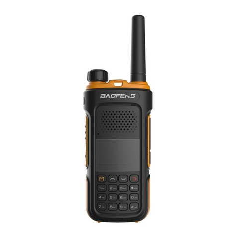
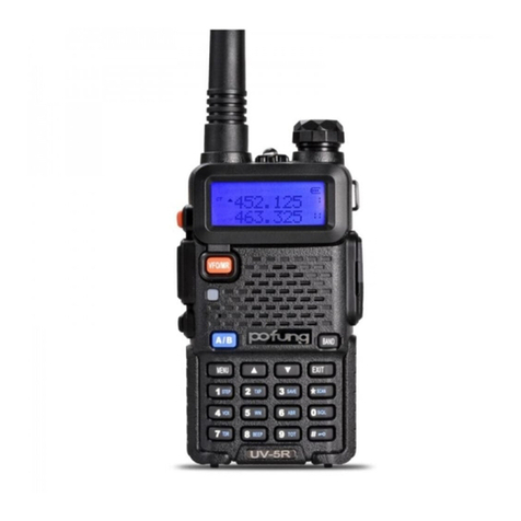
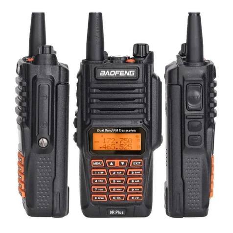
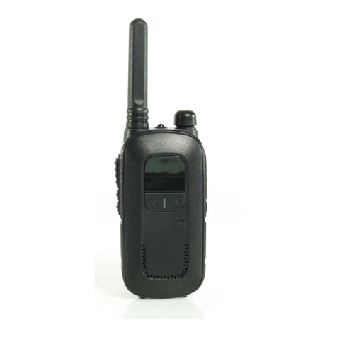
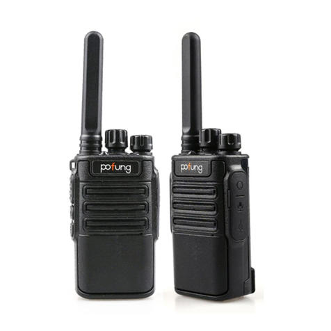
PO Fung Electronic DR-1801 UV Series User manual

Digital DMR and Analog
UHF/VHF Two Way Radio
MENU
BACK
VFO/MR
A/B

1
PREFACE
Thank you very much for choosing our Dual Band Digital DMR and Analog two-way radio. This radio adopts the latest
advances in technology, providing reliable communication in today’s demanding communication environment.
This radio offers both DMR digital and analog communication, introduces innovative DMR digital processing system to
achieve SMS, high-audio quality and digital encryption. It offers great stability, and reliability, together with long distance
communication as well as fashionable design and compact exterior lines. The radios has Text Messaging, Voice Message,
Digital Encryption, Emergency Alarm, Work Alone, Analog DTMF, CTCSS/DCS encode/decode functions.
ATTENTION!
>> When programming the radio, start by reading the factory software data, and then rewrite this data with your
frequency etc., to a new saved code plug, otherwise errors may occur.
>> You can use the programming cable with a PC to program the frequency, power etc. your programming must comply
with your FCC (or other country) license certification.
RF ENERGY EXPOSURE AND PRODUCT SAFETY GUIDE FOR PORTABLE TWO-WAY RADIOS
ATTENTION!
Before using this product, read the RF Energy Exposure and Product Safety Guide that ship with the radio which contains
instructions for safe usage and RF energy awareness and control for compliance with applicable standards and regulation.

2
Table of Contents
GETTING STARTED 9. Monitor 21
1. Regulations and Safety Warnings 03 10. Emergency Alarm 22
2. Feature Overview 08 11. Locking or Unlocking Keypad 22
3. Unpacking and checking the equipment 09 12. Inputting via Keypad 22
4. Battery Information 09 13. Battery voltage test 22
PREPARATION ADVANCED FEATURES
1. Installing / Removing the Battery 12 1. Access Advanced Features for Private Call 23
2. Installing / Removing the Antenna 12 2. Set Up Advanced Features for Private Call 23
3. Installing / Removing the Belt Clip 12 MAIN MENU FUNCTIONS
4. Installing the Additional Speaker/Microphone 13 1. Contacts 24
RADIO OVERVIEW 2. Message 24
1. The main display 14 3. Call Logs 24
2. Description of LCD Icons 14 4. Zone 25
3. Status Indications 16 5. Scan 25
4. Programmed Key 16 6. Settings 26
BASIC OPERATIONS 6.1 Radio Set 26
1. Power on the Radio 18 6.2 Radio Info 30
2. Adjust Volume 18 6.3 Radio Cfg 31
3. Main Band/Sub Band Switch 18 PROGRAMMING GUIDE
4. VFO/Channel Switch 18 Appendix A. - Technical Specifications 35
5. Set Up VFO Frequency 18 Appendix B. - Trouble shooting guide 36
6. Selecting a Zone 18 Appendix C. - CTCSS Table 37
7. Select a Channel 19 Appendix D. - DCS Table 38
8. Call Services 19

3
GETTING STARTED
1. Regulations and Safety Warnings
FCC Licensing Information
This device complies with Part 90 and 15 of the federal Communications Commission (FCC) Rules.
Operation is subject to the condition that that this device does not cause harmful interference. The radio operates on radio
frequencies that are regulated by the Federal Communications Commission (FCC). To transmit on these frequencies, you
are required to have a license issued by the FCC. To obtain forms, call the FCC forms hotline at: 1-800-418-3676 or go to
http://www.fcc.gov For questions concerning commercial licensing, contact the FCC at 1-888- CALL-FCC (1-888-225-5322).
Before filling out you application, you must decide which frequency you can operate on.
NOTICE: Use of this radio outside the country where it was intended to be distributed is subject to government
regulations and may be prohibited.
FCC Regulatory Conformance
This equipment has been tested and found to comply with the limits for a Class B digital device, pursuant to Part 15 of FCC
Rules. These limits are designed to provide reasonable protection against harmful interference in a residential installation.
This equipment generates and can radiate radio frequency energy. If not installed and used in accordance with the
instructions, it may cause harmful interference to radio communications. However, there is no guarantee that interference
will not occur in a particular installation. Verification of harmful interference by this equipment to radio or television
reception can be determined by turning it off and then on. The user is encouraged to try to correct the interference by one
or more of the following measures:
- Reorient or relocate the receiving antenna.

4
- Increase the separation between the equipment and receiver.
- Connect the equipment into an outlet on a circuit different from that to which the receiver is connected.
- Consult the dealer or an experienced radio/TV technician for help.
Changes or modifications not expressly approved by the party responsible for compliance could void the user's authority to
operate the equipment.
This device complies with Part 15 of the FCC Rules. Operation is subject to the condition that this device does not cause
harmful interference.
WARNING!WARNING: MODIFICATION OF THIS DEVICE TO RECEIVE CELLULAR RADIOTELEPHONE SERVICE SIGNALS IS
PROHIBIITED UNDER IC RULES AND FEDERRAL LAW.
EU Regulatory Conformance
As certified by the qualified laboratory, the product is in compliance with the essential requirements and other relevant
provisions of the Directive 2014/53/EU. All applicable EU regulations are regarded (2006/66/EC, 2011/65/EU,(EU)2015/863,
2012/19/EU). NOTE: It can be operating under 2000m.
WARNING!European Users should note that operation of this unit in Transmit mode requires the operator to have a
valid Amateur Radio License from their respective Countries Amateur Radio Licensing Authority for the Frequencies and
Transmitter Power levels that this Radio transmits on. Failure to comply may be unlawful and liable for prosecution. At this
subject, refer to the “EU” specification guide 2014/53/EU.
Please note that the above information is applicable to EU countries only.
Compliance with RF Exposure Standards
The radio complies with the following RF energy exposure standards and guidelines:
•United States Federal Communications Commission, Code of Federal Regulations; 47 CFR § 1.1307, 1.1310 and 2.1093
•American National Standards Institute (ANSI) / Institute of Electrical and Electronic Engineers (IEEE) C95.1:2005; Canada

5
RSS102 Issue 5 March 2015
•Institute of Electrical and Electronic Engineers (IEEE) C95.1:2005 Edition
RF Exposure Compliance and Control
Guidelines and Operating Instructions
To control your exposure and ensure compliance with the occupational/ controlled environmental exposure limits, always
adhere to the following procedures.
Guidelines:
•Do not remove the RF Exposure Label from the device.
•User awareness instructions should accompany device when transferred to other users.
•Do not use this device if the operational requirements described herein are not met.
Operating Instructions:
•Transmit no more than the rated duty factor of 50% of the time. To transmit (talk), press the Push-to-Talk (PTT) key. To
receive calls, release the [PTT] key. Transmitting 50% of the time, or less, is important because the radio generates
measurable RF energy only when transmitting (in terms of measuring for standards compliance).
•Keep the radio unit at least 2.5cm away from the face. Keeping the radio at the proper distance is important as RF
exposure decreases with distance from the antenna. The antenna should be kept away from the face and eyes.
•When worn on the body, always place the radio in an approved holder, holster, case, or body harness or by use of the
correct clip for this product. Use of non-approved accessories may result in exposure levels which exceed the FCC's
occupational/ controlled environmental RF exposure limits.
•Use of non-approved antennas, batteries, and accessories causes the radio to exceed the FCC RF exposure guidelines.
•Contact your local dealer for the product's optional accessories.

6
■Precautions for Portable Terminals
Operating Prohibitions
To protect you against any property loss, bodily injury or even death, be sure to observe the following safety instructions:
1. Do not operate the product in a location containing fuels, chemicals, explosive atmospheres and other flammable or
explosive materials. In such location, only an approved Ex-protection model is allowed for use, but any attempt to
assemble or disassemble it is strictly prohibited.
2. Do not operate the product near or in any blasting area.
3. Do not operate the product near any medical or electronic equipment that is vulnerable to RF signals.
4. Do not hold the product while driving.
5. Do not operate the product in any area where use of wireless communication equipment is completely prohibited.
Important Tips
To help you make better use of the product, be sure to observe the following instructions:
1. Do not use any unauthorized or damaged accessory.
2. Keep the product at least 2.5 centimeters away from your body during transmission.
3. Do not keep the product receiving at high volume for a long time.
4. For vehicles with an air bag, do not place the product in the area over the air bag or in the air bag deployment area.
5. Keep the product and its accessories out of reach of children and pets.
6. Please operate the product within the specified temperature range.
7. Continuous transmission for a long time may lead to heat accumulation within the product. In this case, please keep it
at a proper location for cooling.
8. Handle the product with care.
9. Do not disassemble, modify or repair the product and its accessories without authorization.
■Precautions for Batteries
Charging Prohibitions
To protect you against any property loss, bodily injury or even death, be sure to observe the following safety instructions:
1. Do not charge or replace your battery in a location containing fuels, chemicals, explosive atmospheres and other
7
flammable or explosive materials.
2. Do not charge your battery that is wet. Please dry it with a soft and clean cloth prior to charge.
3. Do not charge your battery suffering deformation, leakage and overheat.
4. Do not charge your battery with an unauthorized charger.
5. Do not charge your battery in a location where strong radiation is present.
6. Overcharge shall always be prohibited for it may shorten the life of your battery.
Maintenance Instructions
To help your battery work normally or prolong its life, be sure to observe the following instructions:
1. Accumulated dust on charging connector may affect normal charging. Please use a clean and dry cloth to wipe it on a
regular basis.
2. It is recommended to charge the battery under 5℃~40℃. Violation of the said limit may cause battery life reduction or
even battery leakage.
3. To charge a battery attached to the product, turn it off to ensure a full charge.
4. Do not remove the battery or unplug the power cord during charging to ensure a smooth charging process.
5. Do not dispose of the battery in fire.
6. Do not expose the battery to direct sunlight for a long time nor place it close to other heating sources.
7. Do not squeeze and penetrate the battery, nor remove its housing.
Transportation Instructions
1. Damaged batteries must not be transported.
2. To avoid short circuit, separate the battery from metal pars or from each other if two or more batteries are transported
in one packaging.
3. The radio must be switched off and secured against switch-on, if the battery is attached.
The content of the shipment must be declared in the shipping documents and by a Battery Shipping Label on the packaging.
Contact your hauler for the local regulations and further information.

8
2. Feature Overview
•Large-capacity storage to meet complex application needs
1024 channel storage, 1024 digital contacts can be manually programmed
•DMO True 2-Slot Two time slots
Direct-mode Dual-Slot communication, enabling two groups of calls to be simultaneously performed at one frequency, to
make double communication efficiency; while saving frequency resources
•Rich digital signaling
It not only supports Private Call, Group Call, All Call and alarm call of DMR protocol; also supports radio detection, Call Alert,
Remote Monitor, Remote Active and Remote Kill and short message data transmission.
•Digital and analog compatible, smooth transition
Support DMR digital and analog two communication modes, ensure that the original analog products smooth transition to
digital products to meet different communication needs.
•SMS function
Support Chinese and English language, support for 64-character text messaging, text editing, and draft box functions.
When it is not convenient to make a voice call, you can send a message by sending a message to the other party.
•Excellent sound quality compatible with Motorola
This digital radio uses advanced AMBE+2TM voice processing technology to achieve excellent call quality.
•Digital encryption function
Digital signal encoding and decoding, improves voice call quality; digital encryption provides security for your voice calls
•Digital alarm function, protect the safety of the team
Supports regular alarms .silent alarms and working alone in emergencies
•Support DMR system, easy to interconnect
Support DMR digital repeater function, easy network scheduling and control globally through IP interconnection

9
3. Unpacking and checking the equipment
Unpack the radio carefully. We recommend that you idenfy the items listed in the following table before discarding the
packing materials.
NOTE: If any of these items are missing from the box, contact your place of purchase immediately.
Supplied Accessories
Antenna 1 Li-ion Battery Pack 1
Baery Charger 1 AC Adaptor 1
Belt Clip 1 Hand Strap 1
Instrucon Manual 1
4. Baery Informaon
Charging the Baery Pack
The Li-ion baery pack is not charged at the factory; please charge it before use. Charging the baery pack for the rst
me aer purchase or extended storage (more than 2 months) may not bring the baery pack to its normal maximum
operang capacity. Best operaon will require fully charging/ discharging the baery two or three mes before the
operang capacity will reach its best performance. The baery pack life may be depleted when its operang me
decreases even though it has been fully and correctly charged. If this is the case, replace the baery pack.
Charger Supplied
Please use the designated charger provided by our company. Other models may cause explosion and personal injury. Aer
installing the baery pack, and if the radio displays low baery with a red ashing lamp or voice prompt, please charge the
baery.

10
Use Caution with the Li-ion Battery
(1) Do not short the battery terminals or throw the battery into a fire. Never try to remove the case from the battery pack,
as our company is not responsible for any accidents caused by modified batteries.
(2) The ambient temperature should be between 5℃-40℃(40˚F - 105˚F) while charging the battery. Charging outside this
range may not fully charge the battery.
(3) Please turn off the radio before inserting it into the charger. It may otherwise interfere with correct charging.
(4) To avoid interfering with the charging cycle, please do not cut off the power or remove the battery during charging until
the green light is on.
(5) Do not recharge the battery pack if it is fully charged. This may shorten the life of the battery pack or damage the
battery pack.
(6) Do not charge the battery or the radio if it is damp. Dry it before charging to avoid damage.
WARNING:
» When keys, ornamental chain or other electric metals contact the battery terminal, the battery may become damage or
injure a human. If the battery terminals are short circuited it will generate a lot of heat.
Take care when carrying and using the battery. Remember to put the battery or radio into an insulated container. Do not
put it into a metal container.
How to Charge
Follow these steps to hook up and use the charger:
(1) Plug the DC connector of the power adaptor into the charger base.
(2) Plug the AC connector of the power adaptor into a main AC wall outlet.
(3) Place the radio in the charging slot on the charger.
(4) Make sure the radio is making contact with the charger. When the red LED comes on steady, your radio is charging.

11
(5) The radio is fully charged once the charger's green status LED goes steady. Please remove the radio at that time to avoid
over-charging your battery.
Charger LED codes
Red LED Green LED
Green LED
Status
Flashing
Steady
Standby (charger empty)
Error (charger with radio)
Steady
Off
Charging
Off
Steady
Charge complete.
The charger and battery are fitted with matching notches so that you can charge your battery on its own! Practical if you
have two batteries. That way you can charge one battery while still using your radio.
Radio should be turned OFF during charge cycle.
How to Store the Battery
(1) If the battery needs to be stored, keep it in status of 80% discharged.
(2) It should be kept in low temperature and dry environment.
(3) Keep it away from hot places and direct sunlight.
(4) To avoid severe capacity degradation of your battery while in long-term storage, please cycle the battery at least every
six (6) months.
NOTE:
»Do not short circuit the battery terminals.
» Never attempt to remove the casing from the battery pack.
» Never store the battery in unsafe surroundings, as a short may cause an explosion.
» Do not put the battery in a hot environment or throw it into a fire, as it may cause an explosion.

12
PREPARATION
Assembly
Before the radio is ready for use we need to attach the antenna and battery pack, as well as charge the battery.
1. Installing / Removing the Battery
Before attaching or removing the battery make sure your radio is turn off by turning the power/volume knob all the way
counter-clockwise.
(1) Installation
Make sure the battery is aligned in parallel with the radio body with the lower edge of the battery about 1-2cm below the
edge of the radio.
Once aligned with the guide-rails, slide the battery upward until you hear a click as the battery locks in place.
(2) Removal
To remove the battery, press the battery release above the battery pack, as you slide the battery downward.
2. Installing / Removing the Antenna
(1) Installing the Antenna: Screw the antenna into the connector on the top of the transceiver by holding the antenna at
its base and turning it clockwise until secure.
(2) Removing the Antenna: Turn the antenna counter-clockwise to remove it.
3. Installing / Removing the Belt Clip
(1) Installing the Belt Clip: Place the belt clip above the corresponding holes on the back of the radio, and screw it into
place clockwise with the two supplied screws.
(2) Removing the Belt Clip: Unscrew counter-clockwise to remove the belt clip.

13
4. Installing the Additional Speaker/Microphone (Optional)
Pry open the rubber MIC-Headset jack cover and then insert the Speaker / Microphone plug into the double jack.
Accessory jack
The accessory jack on the radios is a Kenwood compatible two (2)-pin design.
Typical 2 pin Kenwood headset configuration.
• To attach accessories such as headsets, speaker-mics or programming
cables, align the connectors and push in fully.
• The fit isn't always perfect on cheap or clone cables and connectors and
may require a bit of force to wiggle them in completely.
• Make sure the radio is off before attaching any accessories.
RADIO OVERVIEW

14
1. The main display
2. Description of LCD Icons
Icon name
Icon
Description of product status
Signal strength
The more signal bars, the stronger thesignal is
Transmission power
The currentchannel transmits at high power
The current channel transmits at low power
Digital icon
Digital mode
Analog icon
Analog mode
Direct mode slot icon
The currentchannel is in double slot direct mode and slot 1 is active
The currentchannel is in double slot direct mode and slot 2 is active
Sub-codes
CT
The current sub-codes is CTCSS
DCS
The current sub-codes is CDCSS
Speaker icon
Speaker is enabled, and reception is effective

15
Narrowband mode
N
Work in narrowband mode
Message icon
Receive a text message, or have an unread message
VOX icon
VOX has been turned on
Relay mode icon
The current transmission frequency is the reception frequency plus a frequency
bias (positive bias)
The current transmission frequency is the reception frequency minus a frequency
bias (negative bias)
Currently in offline state
Keyboard Lock icon
The keyboard lock is locked; Lock status. Press thecombo keys [MENU] and [*]
to unlock
Scrambling icon
R
The current reception frequency and the transmission frequency are inverted (if
the reception sub-code and transmission sub-code are different, the sub-code
will also be inverted)
Double-waiting icon
S
Has been set to dual-band Double-Wait function, and allows waiting on two
frequency bands displayed on thescreen at the same time
Scan icon
The scan is on and is in normal mode
The scan stays on priority channel 1
The scan stays on priority channel 2
Battery power icon
The more bars, the more battery power
Pointer icon
Currently pointing to the main digital mode; press A/B key to switch the main
channel up and down. When double-waiting is turned on and works in digital
sub-channel, the icon is
Currently pointing to the main analog mode; press A/B key to switch the main

16
channel up and down. When double-waiting is turned on and works in analog
sub-channel, the icon is
Channel number icon
001
In channel mode, the current channel number is 001 (range 1~32)
3. Status Indications
The top LED will help you to identify the current radio status.
LED Indication
Status
Flashes Red
Low battery voltage
Constant Red
Transmitting
Constant Green
Analog and Digital Receiving
Flashes orange slowly
Scanning
4. Programmed Key
It is possible to set different functions for [SK1], [SK2], [TK] keys.
In PC software –Operation –Key Settings.
No.
Shortcut name
Purpose
1
None
No function is assigned to the preset key.
2
Emergency on
To initiate an emergency alarm. This is a recommended option for "TK Short".
3
Emergency off
To end an emergency alarm. This is a recommended option for "TK Short".
4
High/Low power
To switch the power level between High and Low.
5
Monitor
Monitor the weak signal or the signal with unmatched ID.
6
One Touch Access1-5
To make a call or send a message to the preset contact or implement an auxiliary feature.
7
Repeater/Talk Around
To switch between Direct mode and Repeater mode.

17
8
VOX On/Off
To enable or disable the VOX feature.
9
Scan on / off
Quickly turn the scan function on or off.
Note: double-segment double-waiting scan does not work.
10
Encryption on/off
Quickly turn on/off encryption for channel (only for digital mode).
11
VOX On/Off
To enable or disable the VOX feature.
12
Zone select
Quickly select the zone, allowing the user to switch between two zones.
13
Battery Indication
Quickly access to battery power. The user can check the battery status by LED. The battery
power is sufficient if the LED is constantly in green, the battery power is still available if the
LED is constantly in yellow, and the battery power is low if the LED is in red.
14
Lone Worker On/Off
To enable or disable the Lone Worker feature.
15
Phone Exit
Quickly end the phone call (only for digital mode).
Note:
●Depending on dealer setting, different functions can be achieved by pressing and pressing and holding the same key.

18
BASIC OPERATIONS
1. Power on the Radio
Turn on the radio by turning the [Power/Volume] switch clockwise till a click is heard, and the LCD displays will show a
start-up message, and you will hear a beep after 7 seconds.
2. Adjust Volume
Rotate the [Power/Volume] knob to adjust the volume. Turn clockwise to increase the volume and counterclockwise to
decrease the volume.
3. Main Band/Sub Band Switch
Press the [A/B] key to switch the main channel to the other channel if there is 2 channels shown on the display. The
channel indicated by the arrow is the main channel.
4. VFO/Channel Switch
Press the [VFO/MR] key to switch between VFO and channel display.
5. Set Up VFO Frequency
Press the [VFO/MR] key to tune the radio to VFO mode, then press the [A/B] key to switch to the main band, the VFO
frequency can only be set on the main "arrow" channel.
Operation 1: Input the VFO frequency directly by the keyboard.
Operation 2: Press the or navigation keys to adjust the VFO frequency in preset steps.
6. Selecting a Zone
A zone is a group of channels with the same property. The radio supports up to 150 zones, with a maximum of 32 channels
per zone. To select a zone, do one of the following:

19
Operation 1: Go to Menu > Zone, press or navigation key to select a zone, and then press [MENU] key to switch to
the selected zone.
Operation 2: Press the preprogrammed [Zone Select] key to switch to the selected zone.
7. Select a Channel
Press [VFO/MR] key to switch the radio between VFO and Channel mode, select Channel mode.
Operation 1: Press the or navigation key to select the channel.
Operation 2: Input the channel numbers by the keyboard. For example, if you want switch to channel 12, input 1+2 a total
of 2 digits, and it will switch to channel 12.
A channel can either be Analog or Digital.
For the analog channels the PTT (Push-To-Talk) key is always available, and on the Digital Channels the parameters can be
set up by the users / system operators by individual channel to allow talk permit.
There are four possible settings that can be selected in the CPS channel:
(1) Always Allow: The user can transmit all the time.
(2) Channel Free: The radio can transmit only if the channel is free.
(3) Same CC/QT: The radio can transmit only if the channel is free and the color code matches.
8. Call Services
When you are speaking during a call, keep the microphone about 2.5 to 5 cm away
from your mouth. This ensures optimal voice quality on the receiving radio. Press the
[PTT] key to start the call, the red LED lights up. Release [PTT] key to receive the reply.
Call on Digital Channel
You can initiate or receive the following types of calls on a digital channel:
•Private Call: a call from an individual user to another individual user.
Table of contents
Other PO Fung Electronic Two-way Radio manuals

PO Fung Electronic
PO Fung Electronic UV-82 Series User manual

PO Fung Electronic
PO Fung Electronic P10UV User manual

PO Fung Electronic
PO Fung Electronic F8 User manual

PO Fung Electronic
PO Fung Electronic UV-9R PRO Series User manual

PO Fung Electronic
PO Fung Electronic MP1 Series User manual

PO Fung Electronic
PO Fung Electronic UV-9G User manual

PO Fung Electronic
PO Fung Electronic BF-H6 User manual

PO Fung Electronic
PO Fung Electronic P11UV User manual

PO Fung Electronic
PO Fung Electronic GT-68 Series User manual

PO Fung Electronic
PO Fung Electronic MP23 Series User manual