PO Fung Electronic MP23 Series User manual

MP23/T23 SERIES
FRS TWO-WAY RADIO
OWNER’S MANUAL

ATTENTION! The radio is a multitask FRS transceiver. Combining the latest technology in radio communication along
with a sturdy mechanical frame, the radio is the ideal and effective solution for the professionals who need to stay in
touch with the working team (in construction sites, buildings, shows, trade fairs or hotels) or for leisure users that just
want to keep up with friends and family.
To help you ward off bodily injury or property loss that may arise from improper operation, please read all the information
carefully before using our products.
Before operating the radio, please read all safety and operating instructions. Save all instructions in a
safe place for future reference.
FCC Part 15.21 Warning Statement
NOTE: THE GRANTEE IS NOT RESPONSIBLE FOR ANY CHANGES OR MODIFICATIONS NOT EXPRESSLY
APPROVED BY THE PARTY RESPONSIBLE FOR COMPLIANCE. SUCH MODIFICATIONS COULD VOID THE USER’S
AUTHORITY TO OPERATE THE EQUIPMENT.
Content of the packaging
Note: The number of the above materials may be depending on the number of packages.
Package Content
General
Extreme
Excellence
Honorable
Radio
2
2
4
6
Li-ion Battery
2
2
4
6
Belt Clip
2
2
4
6
Lanyard
2
2
4
6
Power Adapter
1
1
2
1
Desktop Charger
0
1
2
0
Headset
0
2
4
6
Owner’s Manual
1
1
1
1

Main features
• 22 FRS Channels • Output power: ≤2W (channels 1-7and 15-22)
• 12 NOAA Weather Channels • NOAA Weather Scan
• 2 Channels Watch • Privacy Codes Scan and Store
• Channel Monitor • Channel Scan Function
• 155 Privacy Codes (50 CTCSS codes/ 105 DCS codes) • 10 Selectable Call Alerts
• Hands-Free Operation (VOX) • Call Alert
• Roger Beep Tone • Keypad Lock
• Battery Level Meter • Emergency Strobe Light
• Battery/Power Saver • Backlit LCD Display
• Low Battery Audible Alert • TOT (Time out timer)
• 2pin Kenwood headset jack • Type-C USB connector for charging
• Li-Ion 1500mAh battery pack • Keystroke Tones
• Up to 5 km range* • Battery Life: up to 18 hours (under typical use conditions)
*Range may vary depending on environmental and/or topographical conditions.
Installation of Accessories
Installing and Removing Belt Clips
With the belt clip, you can easily attach the radio to the belt. However, the belt clip must be removed to install or replace the
battery.
To remove the belt clip, follow the illustration. Fasten the clip into the slot on the unit in the radio's rear rail until it snaps
into the square.

Install the Li-ion Battery (BL-T22)
Each radio operates with either a Li-ion battery pack or optional 3 AA
alkaline batteries. The belt clip should be removed (see below) to
ease installation or removal of the batteries.
• Install
1) Remove the belt clip as described in the previous paragraph.
2) Insert the battery pack into the appropriate compartment of the
device.
3) Close the battery compartment with the cover and put the belt
clip back in place
• Remove
1) Remove the belt clip as previously described.
2) Open the battery compartment as shown in the figure;
3) Remove the battery pack from the device;
4) Snap the belt clip back into place.
5) Close the battery compartment with the cover and put the belt clip back in place.
Install three AA Ni-MH Batteries (3 x AA, rechargeable)
Warning: Ni-MH batteries are rechargeable batteries and cannot be mixed with alkaline batteries.
1) Turn off the radio.
2) With the back of the radio facing you, lift up the battery cover latch, and then remove the battery cover.
3) As shown in the figure, insert three AA Ni-MH batteries with + and –polarity (wrong installation of the batteries will cause
the unit to fail or damage the unit).
4) Close the battery cover. Replace the belt clip and make sure it locks in place.
Installing the Three AA Alkaline Batteries (non-rechargeable)
Warning: Alkaline batteries can only be used in emergency situations and cannot be charged. There is a danger of

explosion when charging alkaline batteries.
1) Turn the radio off.
2) With the back of the radio facing you, lift the battery cover latch up and remove the cover.
3) Insert the three AA Alkaline batteries with + and –polarity as shown inside (Installing the batteries incorrectly will prevent
the unit from operating or may damage the unit).
4) Close the battery cover. Replace the belt clip, making sure it locks into place.
External Speaker/Microphone Jack
Each radio can be used with an optional external speaker/microphone or headset, freeing your hands for other tasks. To use
an optional speaker / microphone or headset:
1) Open the rubber cap on the side of the radio.
2) Insert the plug(s) into the SPK/MIC jacks.
3) Place the ear bud into your ear, and adjust the Microphone into your desired position.
Using a Headset
You can use a headset (#480_5R) for more private communications. To use a headset, lift the rubber cover from over the
headset jack, and then plug in the headset.
Important: Your radio is not submersible or waterproof when using a headset jack. When you remove the headset, be sure
to fully press the jack cover into place to restore its waterproof capability.
Charging the Battery
Charging the Radio
Two radios can be charged directly by using the supplied charging cradle. A single radio can charge using the Type-C USB port
to connect to a USB power source. For fastest charging, turn off the radio before charging.
Warning!
To avoid the risk of personal injury or property damage from fire or electrical shock, only use the accessories specifically
designated for this product. Using the Type-C USB Port

1) Connect the included AC adapter with Type-C USB connector cable to the radio's Type-C USB port. Connect the other end
to an outlet that provides USB charging power (NOT to a USB hub).
2) Charge the batteries for 6 hours until the battery indicator either stops flashing.
Using the Charging Cradle
1) Connect the included AC adapter with USB connector cable to the charging cradle's Type-C USB port. Connect the other
end to a standard AC wall outlet.
2) Set the charging cradle on the desk or tabletop, and place the radio in the charging cradle with the keypad facing forward.
3) Charge the batteries for 6 hours.
Note:
• Use only the supplied batteries, charger, and AC adapter or approved accessories.
• Charge time may vary depending on the battery life remaining.
• The batteries must be installed for the unit to operate, even if the unit is also connected to external power.
• If battery power is low, you cannot operate the radio even using external power. Allow the batteries to charge before using.
*If you try to transmit while power is low, the radio will automatically turn off.
Warning: Do not charge alkaline batteries. The radio will not be used for a long time, please take out and keep the
battery properly.
Using the Radio Battery Level and Low Battery Alert
This radio has a Battery Level Meter that shows the battery power level. The greater the number of bars visible, the
stronger the battery level. When the battery level is low, the Battery Shell icon will flash in the display indicating your
batteries should be replaced or recharged if using a rechargeable battery pack.
Warning! To avoid the risk of personal injury or property damage from fire or electrical shock, only use accessories
specifically designated for this product.

Main controls and parts of the radio
1. Antenna
2. LCD Display
3. UP button - Press to increase the volume. Menu mode
to change settings in MENU.
4. /MENU- Press this control to enter the radios MENU. If
you keep it pressed for about 3 seconds, the keypad lock is
activated.
5. /CALL - To send a call to the selected channel. keep
pressed to turn on/off the radio.
6. DOWN button - Press to reduce the volume. menu mode
to change settings in MENU.
7. Speaker and Built-in microphone
8. LED Flashlight
9. Led indicator: RED - TX; GREEN - RX.
10. Weather/ MONI button: Short press to switch between Weather and FRS channels. Keep pressed to activate the Monitor
function (for weak signal monitoring).
11. SPK | MIC (under the protective cover) - To connect to external audio devices such as microphones, headphones, etc
12. /SCAN button - Press this button once to activate SCAN.
13. USB port for the recharge of the radio
14. PTT button (Push-To-Talk)
15. LAMP/ Emergency button - When the radio is switched on, press shortly to turn on/off the LED flashlight. keep
pressed to turn on/off the emergency alerts.

LCD DISPLAY
Basic Operations
In order to get the most out of your new radio, read this reference guide completely before attempting to operate the unit.
Power on/off and volume adjustment
To turn the radio on, keep pressed the [/CALL] button.
To adjust the volume level as you prefer, press the [ ] or [ ] button.
In case the radio does not pick up any signal, activate momentarily the Monitor function that allows to detect also weak
signals. Then, adjust the volume to the desired level.
To turn the radio off, keep pressed the [ /CALL] button until a switch off tone is heard.
Keypad Lock
To avoid accidentally changing the radio settings, press the [ /MENU] button for 3 seconds. The icon will appear on the
display. [PTT], , [/CALL] and [MONI] keys will still be active. Repeat the same procedure to unlock the keypad.
1. NOAA Weather Band Indicator
2. Scan Indicator
3. Activate the VOX function
4. Dual Channel Monitor
5. Select the DCS/CTCSS type of squelch method
6. Channel (1-22)
7. Battery Indicator
8. Emergency alert function activated
9. Transmit Status
10. Receive Status
11. Keypad Lock
12. Transmit power indicator. Low power only in PMR
mode
13. Displays the set CTCSS tone or DCS code (CTCSS:
1-50; DCS: 1-105)

Talking on Your Radio
To talk to others using the radio:
1) Press and hold the [PTT] button and speak in a clear, normal voice about 2-3 inches away from the microphone. While you
are transmitting, the TXicon appears on the display. To avoid cutting off the first part of your transmission, pause
slightly after pressing the [PTT] button before you start talking.
2) When you have finished speaking, release the [PTT] button. You can now receive incoming calls. While receiving, RX
displays.
Monitor Mode Feature
Your radio allows you to listen for weak signals on the current channel at the press of a key. To turn ON Monitor mode: Press
and hold [ /MONI] for 2 seconds until two beeps sound. The receiver circuit stays open, and both noise and weak signals
can be heard. The RXicon blinks. To turn OFF Monitor mode: Press and hold [ /MONI] for 2 seconds to return to
"Normal" mode; two beeps sound and the RXicon stops blinking and disappears.
Channel Scanning
MP23/T23 can automatically search for signals throughout the FRS bands by scanning, i.e. selecting the channels in rapid
sequence. When a signal is detected, the scanning pauses on that channel and you can transmit by pushing [PTT]. If you
press [PTT] during scanning you can transmit on the channel from which the scanning started. The scroll buttons [ ] or [ ]
allow you to change the direction of scanning (from lower channels to higher ones or vice versa) and therefore to skip
communications which are of no interest.
Press briefly the button [ /SCAN] to start scanning.
If you want to stop it, press again [ /SCAN]. Your transceiver will go back to the channel from which the scanning originally
started.
Scanning Sub-Codes
Press and hold [ /SCAN] button to enter the Sub-Codes scanning.

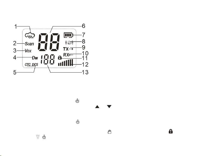
A flashing "CTC/DCS" will be in the left status display to indicate the radio is in Sub-Codes scanning mode.
In this mode, the lower display will cycle through the Sub-Codes as they are being tested. Once the bits of the received
Privacy code are determined, the "CTC/DCS" indicator will stop flashing.
Press the [PTT] button to save the scanned tone into memory.
During scanning, press and hold [ /SCAN] button to exit Sub-Code scanning.
Using the Flashlight
You can use this radio in an emergency. If you press [ ] button, the radio turns on the high-intensity LED flashlight on your
radio.
• Your radio operates normally when the emergency strobe is activated.
1) Press [ ] button once, it will turn on continuously (Always On mode) .
2) And then, press [ ] button once, the Strobe Light emits the emergency signal. (Strobe emergency mode).
3) And then, press [ ] button once, the light will be turned off.
Emergency Alert
The Emergency Alert feature can be used to signal members in your group for help. The emergency alarm function is
activated by menu operation.
To activate the emergency alert function, press and hold the [ ] button for 3 seconds. The radio will send out a loud siren
sound and the flashlight will flash.
Press the [ ] button to exit the emergency alert function.
WARNING: The Emergency Alert feature should only be used in the even of an actual emergency.
Using the Weather Radio/Scan Weather Channel
Your radio has a NOAA Weather Radio function, to enable the user to receive weather reports from designated NOAA
stations. Your radio also has a NOAA Weather Scan function, to enable the user to scan all 12 channels of the NOAA Weather
Radio. While using the Weather Radio, you are not able to receive FRS communications.

1) To turn the NOAA Weather Scan on, press and hold the [ /MONI] button for 5 seconds while in FRS mode, icon
appears. The radio will go to Weather band mode and start scanning all 12 channels and stop on any active channel.
When the channel becomes inactive for 10 seconds the radio will resume scanning.
2) To stop the NOAA WEATHER (WX) SCAN and set the channel manually on the Weather band, press the [SCAN] button
during NOAA weather scan. The radio will stop scanning and the display will show the current Weather band channel
setting and the icon.
3) While in Weather band mode, press the [ /MENU] button, then press the [ ] or [ ] button to increase or decrease
the number to the desired weather channel, and press the [ /MENU] button to confirm to select one of the 12 NOAA
weather band channels.
4) To exit the Weather Radio broadcast mode, press and hold [/MONI] button. icon disappears.
Menu Options
FRS Menu List

Selecting the Channel
The channel is the frequency of the radio uses to transmit. Your radio has 16 channels and 155 Sub-Codes you can use to talk
to others. In order to speak to someone, both your radios must be set to the same channel and Privacy code.
1) Press and hold the [/CALL] button until the radio is turned on.
2) Press [ /MENU] button until the channel number starts to flash.
3) Press [ ] or [ ] to change the channel. Long press on these keys allows you to scroll through the channels rapidly to
browse the codes.
4) Press [PTT] button to exit menu or [ /MENU] button to continue set up.
If the [ /MENU] button is locked, please press and hold the [ /MENU] button for 3 seconds to unlock.
CTCSS/DCS tones selection
MP23/ T23 can receive in two modes:
• Open traffic: in this case you will hear any communication transmitted on the selected channel;
• Group mode CTCSS/DCS: CTCSS/DCS tones are access keys that allow you to receive only messages coming from parties
using the same channel and code. The speaker will remain muted until the correct tone is received.
To activate 1 of 50 different CTCSS/105 DCS tones in RX and TX
1) To select CTCSS/DCS, press [ /MENU] twice until the display shows CTC or DCS (flashing on the lower left).
2) By pushing the [ ] or [ ] button the display will show CTCSS (ct blinking) or DCS (dc blinking); press [ /MENU] to enter
the CTCSS or DCS tones. Now select the desired tone with the [ ] or [ ] buttons.
3) Press the [PTT] button to exit menu or [ /MENU] button to continue set up.
VOX function
MP23/ T23 enables hands free conversations through VOX function.
1) To activate VOX function press the [ /MENU] button 4 times and ‘VOX’will appear on the display.
2) Use the [ ] or [ ] buttons to select the desired setting:
The VOX sensitivity can be set in 3 different levels:

• 1 = high sensitivity (normal voice with no background noise)
• 2 = Medium Sensitivity for most environments
• 3 = low sensitivity (useful in very noisy areas or if you talk loudly)
3) Press the [PTT] button to exit menu or [ /MENU] button to continue set up.
To disable the VOX function follow the instructions above and select option oF (OF: Disabled).
Setting and Transmitting Call Tones
MP23/ T23 can transmit different call tones to other radios in your group so you can alert them that you want to talk. Your
radio has 10 call tones for you to choose from.
To select the call tones:
1) Press the [ /MENU] button 5 times and " " will appear on the display.
2) Press [ ] or [ ] to change and listen to the call tone.
3) Press the [PTT] button to exit menu or [ /MENU] button to continue set up.
• To disable the Call Tones follow the instructions above and select option oF (OF: Disabled).
In order to transmit your call tone to other radios, set up the same channel and Sub-Code on your radio and press the
[/CALL] button.
Emergency alarm type
With the emergency alert feature, you can signal to your group members that you need help. The alarm signal can only be
signaled that you need help by pressing and hold the [ ] button after the emergency alarm function of the MP23/ T23 is
activated.
Select an emergency alert type:
1) To activate emergency alert function press the [ /MENU] button 6 times and until the display shows “ ”.
2) Use the [ ] or [ ] buttons to select the desired setting:
oF: Disabled
1. Local alarm, the radio itself emits an alarm sound;
2. Send an alarm tone on the current channel to signal to group members that you need help.

3) Press the [PTT] button to exit menu or [ /MENU] button to continue set up.
WARNING: The Distress Alert feature should only be used in a true emergency. If the receiving group does not respond to the
distress signal, Baofeng will not assume any responsibility.
Keypad beep
To deactivate the keypad beep, follow these steps:
1) Press the [ /MENU] button 7 times and until “ ” is displayed.
2) Use the [ ] or [ ] buttons until the display shows “ ”.
3) Press the [PTT] button to exit menu or [ /MENU] button to continue set up.
Now you won’t hear any beep at the pressure of any button.
ROGER BEEP (End transmission tone)
When the PTT button is released, the radio will beep to confirm to other users that your transmission has finished.
To deactivate it:
1) Press the [ /MENU] button 8 times and until the display shows “ ”;
2) Using the buttons [ ] or [ ] select “off” and “ ” will be displayed;
3) Press the [PTT] button to exit menu or [ /MENU] button to continue set up.
Dual Watch Mode
Your radio has a DUAL WATCH function, to enable user to scan 2 channels for any activity. The first channel will be the
current channel setting and the second channel will be the selected channel on the.
To set another channel and start Dual Watch:
1) Press the [ /MENU] button 9 times and until the display shows “ ”;
2) Using the buttons [ ] or [ ] select the channel, then press [ /MENU].
3) Using the buttons [ ] or [ ] select the CTCSS/DCS, then press [ /MENU].
4) The radio starts to Dual Watch.
The screen will alternate between home channel and Dual Channel Monitor channel.

Note: If you set the same channel and Sub-code as the current channel, Dual Watch doesn’t work.
5) Press the [ /SCAN] button to turn the Dual Watch mode OFF.
Technical Specifications
General Part
Frequency Range
FRS
Channels
22 FRS/12 Weather
Sub-Codes
50 CTCSS Tones/ 105 DCS Codes
Working temperature
-20℃to +50℃
Operation Voltage
DC 3.7 V ±10%
Operation Mode
Simplex
Dimensions
168mm×57mm×34.5mm (without Antenna)
Weight
150g (Battery pack included)
Antenna Impedance
50ohm
Transmitter Part
Frequency Stability
±2.5ppm
RF Output Power
2W (FRS)
Max frequency deviation
≤2.5KHz
Audio distortion
≤3%
Adjacent Channel Power
<60dB
Receiver Part
Receive Sensitivity
<0.2μV @20dB SINAD
Audio distortion
≤3%
Audio response
300 Hz ~ 3 KHz

Appendix B. –Trouble shooting guide
Phenomena
Analysis
Solution
You cannot turn on the radio.
The battery may be installed improperly.
Remove and reattach the battery.
The battery power may run out.
Recharge or replace the battery.
The battery may suffer from poor contact caused by
dirty or damaged battery contacts.
Clean the battery contacts or replace the
battery.
During receiving, the voice is
weak or intermittent.
The battery voltage maybe low.
Recharge or replace the battery.
The volume level may be low.
Increase the volume.
The speaker maybe blocked.
Clean the surface of the speaker.
You cannot communicate with
other group members.
The frequency or signaling type maybe inconsistent
with that of other members.
Verify that your TX/RX frequency and
signaling type are correct.
You may be too far away from other members.
Move towards other members.
You hear unknown voices or
noise.
You may be interrupted by radios using the same
frequency.
Change the frequency, or adjust the
squelch level.
The radio in analog mode maybe set with no
signaling.
Request your dealer to set signaling for
the current channel to avoid interference
You are unable to hear anyone
because of too much noise
and hiss.
You may be too far away from other members.
Move towards other members.
You may be in an unfavorable position. For
example, your communication may be blocked by
high buildings or blocked in an underground area.
Move to an open and flat area, restart the
radio, and try again.
It may be the result of external disturbance (such as
electromagnetic interference).
Stay away from equipment that may
cause interference.
The radio keeps transmitting.
VOX may be turned on or the headset is not
installed in place
Turn off the VOX function. Check that the
headphones are in place.
NOTE: If the above solutions cannot fix your problems, or you may have some other queries, please contact your dealer
for more technical support.

Appendix C. –FRS Frequency Chart (MHz)
CH.No
CH.Freq.
RF Power
CH.No
CH.Freq.
RF Power
1
462.5625
High
12
467.6625
Low
2
462.5875
High
13
467.6875
Low
3
462.6125
High
14
467.7125
Low
4
462.6375
High
15
462.5500
High
5
462.6625
High
16
462.5750
High
6
462.6875
High
17
462.6000
High
7
462.7125
High
18
462.6250
High
8
467.5625
Low
19
462.6500
High
9
467.5875
Low
20
462.6750
High
10
467.6125
Low
21
462.7000
High
11
467.6375
Low
22
462.7250
High
Appendix D. - NOAA Weather Radio Frequency List (US, CAN, AND INTL)
Channel No.
RX Freq.(MHz)
Channel No.
RX Freq.(MHz)
1
162.5500
7
162.5250
2
162.4000
8
161.6500
3
162.4750
9
161.7750
4
162.4250
10
161.7500
5
162.4500
11
162.000
6
162.5000
12
163.275

Appendix E. - DCS Table
DCS CODE LIST
Number
Code
Number
Code
Number
Code
Number
Code
Number
Code
1
D023
2
D025
3
D026
4
D031
5
D032
6
D036
7
D043
8
D047
9
D051
10
D053
11
D054
12
D065
13
D071
14
D072
15
D073
16
D074
17
D114
18
D115
19
D116
20
D122
21
D125
22
D131
23
D132
24
D134
25
D143
26
D145
27
D152
28
D155
29
D156
30
D162
31
D165
32
D172
33
D174
34
D205
35
D212
36
D223
37
D225
38
D226
39
D243
40
D244
41
D245
42
D246
43
D251
44
D252
45
D255
46
D261
47
D263
48
D265
49
D266
50
D271
51
D274
52
D306
53
D311
54
D315
55
D325
56
D331
57
D332
58
D343
59
D346
60
D351
61
D356
62
D364
63
D365
64
D371
65
D411
66
D412
67
D413
68
D423
69
D431
70
D432
71
D445
72
D446
73
D452
74
D454
75
D455
76
D462
77
D464
78
D465
79
D466
80
D503
81
D506
82
D516
83
D523
84
D526
85
D532
86
D546
87
D565
88
D606
89
D612
90
D624
91
D627
92
D631
93
D632
94
D645
95
D654
96
D662
97
D664
98
D703
99
D712
100
D723
101
D731
102
D732
103
D734
104
D743
105
D754
Note: DCS codes can be programmed for use on Channels 1~22 only.

Appendix F. - CTCSS Table
CTCSS CHART (Hz)
Number
Frequency
Number
Frequency
Number
Frequency
Number
Frequency
Number
Frequency
1
67.0
2
69.3
3
71.9
4
74.4
5
77.0
6
79.7
7
82.5
8
85.4
9
88.5
10
91.5
11
94.8
12
97.4
13
100
14
103.5
15
107.2
16
110.9
17
114.8
18
118.8
19
123.0
20
127.3
21
131.8
22
136.5
23
141.3
24
146.2
25
151.4
26
156.7
27
159.8
28
162.2
29
165.5
30
167.9
31
171.3
32
173.8
33
177.3
34
179.9
35
183.5
36
186.2
37
189.9
38
192.8
39
196.6
40
199.5
41
203.5
42
206.5
43
210.7
44
218.1
45
225.7
46
229.1
47
233.6
48
241.8
49
250.3
50
254.1
Note: CTCSS Chart can be programmed for use on Channels 1~22 only
IMPORTANT NOTICE
WARNINGS: Replacement or substitution of transistors, regular diodes or other parts of a unique nature,
with parts other than those recommended by PO FUNG COMPANY may cause a violation of the technical
regulations of part 95 of the FCC rules, or violation of type acceptance requirements of part 2 of the rules. Your
radio is set up to transmit a regulated signal on an assigned frequency. Any adjustment to your radio must be made by
qualified technicians.
This device complies with Part 15 of the FCC Rules. Operation is subject to the following two conditions: 1) This device may
not cause harmful interference, and 2) this device must accept any interference received, including interference that may
cause undesired operation.

FCC & RSS WARNINGS:
Any Changes or modifications not expressly approved by the party responsible for compliance could void the
user’s authority to operate the equipment.
SAR tests are conducted using standard operating positions accepted by the FCC/ISEDC with the device transmitting at its
highest certified power level in all tested frequency bands, although the SAR is determined at the highest certified power
level, the actual SAR level of the device while operating can be well below the maximum value. Before a new model is a
available for sale to the public, it must be tested and certified to the FCC/ISEDC that it does not exceed the exposure limit
established by the FCC/ISEDC Tests for each product are performed in positions and locations as required by the FCC/ISEDC.
For body worn operation, this device has been tested and meets the FCC/ISEDC RF exposure guidelines when used with an
accessory designated for this product or when used with and accessory that contains no metal.
Tm maintain compliance with the FCC/ISEDC’s RF exposure guidelines, hold the transmitter and antenna at least 25mm from
your face and speak in a normal voice, with the antenna pointed up and away from the face.
This equipment complies with FCC/ISEDC radiation exposure limits set forth for an uncontrolled environment. In order to
comply with the FCC/ISEDC RF exposure requirements, the antenna installation must comply with following:
Users must be fully aware of the hazards of the exposure and able to exercise control over their RF exposure to qualify for
the higher exposure limits.
Your wireless hand-held portable transceiver contains a low power transmitter. This product sends out radio frequency (RF)
signals when the Push-to-Talk (PTT) Button is pressed.
The device is authorized to operate at a duty factor not to exceed 50%.
This device complies with ISEDC licence-exempt RSS standard (s). Operation is subject to the following two conditions:
(1) this device may not cause interference, and (2) this device must accept any interference, including interference that may
cause undesired operation of the device.
Le présent areil est conforme aux CNR d’ISEDC licables aux arels radio exemprs de licence.
This manual suits for next models
1
Table of contents
Other PO Fung Electronic Two-way Radio manuals

PO Fung Electronic
PO Fung Electronic F12 User manual

PO Fung Electronic
PO Fung Electronic F8 User manual

PO Fung Electronic
PO Fung Electronic MP1 Series User manual

PO Fung Electronic
PO Fung Electronic P11UV User manual

PO Fung Electronic
PO Fung Electronic P10UV User manual

PO Fung Electronic
PO Fung Electronic DR-1801 UV Series User manual

PO Fung Electronic
PO Fung Electronic UV-9G User manual

PO Fung Electronic
PO Fung Electronic UV-82 Series User manual

PO Fung Electronic
PO Fung Electronic BF-H6 User manual

PO Fung Electronic
PO Fung Electronic GT-68 Series User manual